Devolo dLAN 200 AVpro Product guide


devolo dLAN® 200 AVpro Project Manual i
© 2009 devolo AG, Aachen (Germany)
This document is copyright-protected. Its contents are confidential. No part of the documentation may be copied in any form, neither electronically nor
mechanically, for any purpose, except for the sole purpose of a project evaluation and only with explicit written authorisation by devolo. devolo reserves the
right to modify any details in this document without notification. devolo cannot be held liable for technical inaccuracies and/or omissions. devolo cannot be
held liable for the correctness and/or completeness of the information in this project manual and for any consequences resulting from the use of this
document.
Trademarks
dLAN® ,devolo and the devolo logo are registered trademarks of devolo AG.
HomePlug®is a registered trademark of HomePlug Power Alliance.
Linux®is a registered trademark of Linus Torvalds.
Mac®is a registered trademark of Apple Computer, Inc.
Windows®and Microsoft®are registered trademarks of Microsoft, Corp.
All other names mentioned may be trademarks or registered trademarks of their respective owners.
Revision
10.1 (1 July 2009)
10.2 (11 September 2009)

devolo dLAN® 200 AVpro Project Manual ii
Contents
1Introduction .................................................................................................................. 1
2Important basics ........................................................................................................... 2
2.1 Attenuation ....................................................................................................................................2
2.2 Frequencies.....................................................................................................................................2
3Antenna networks ........................................................................................................ 4
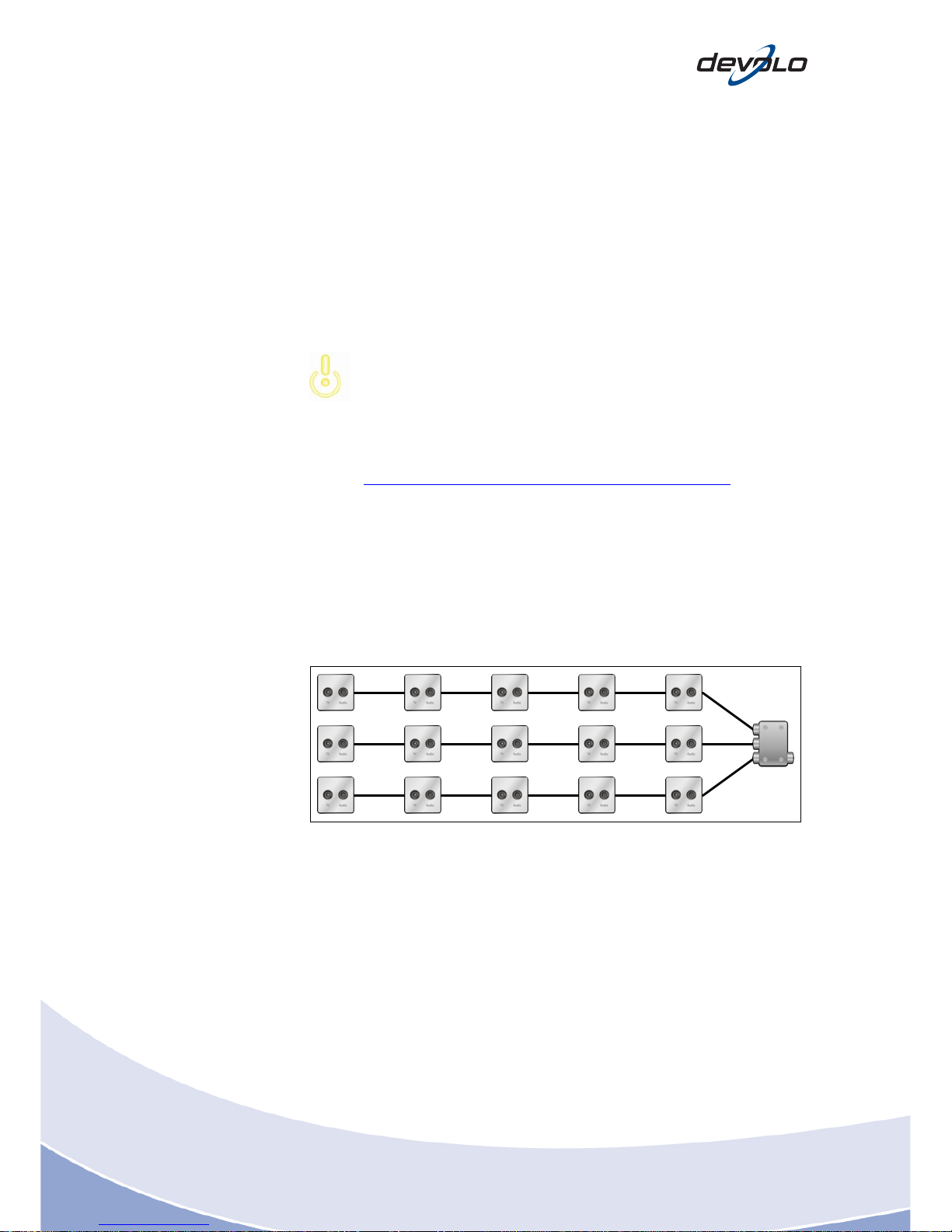
3.1 Network topologies.........................................................................................................................4
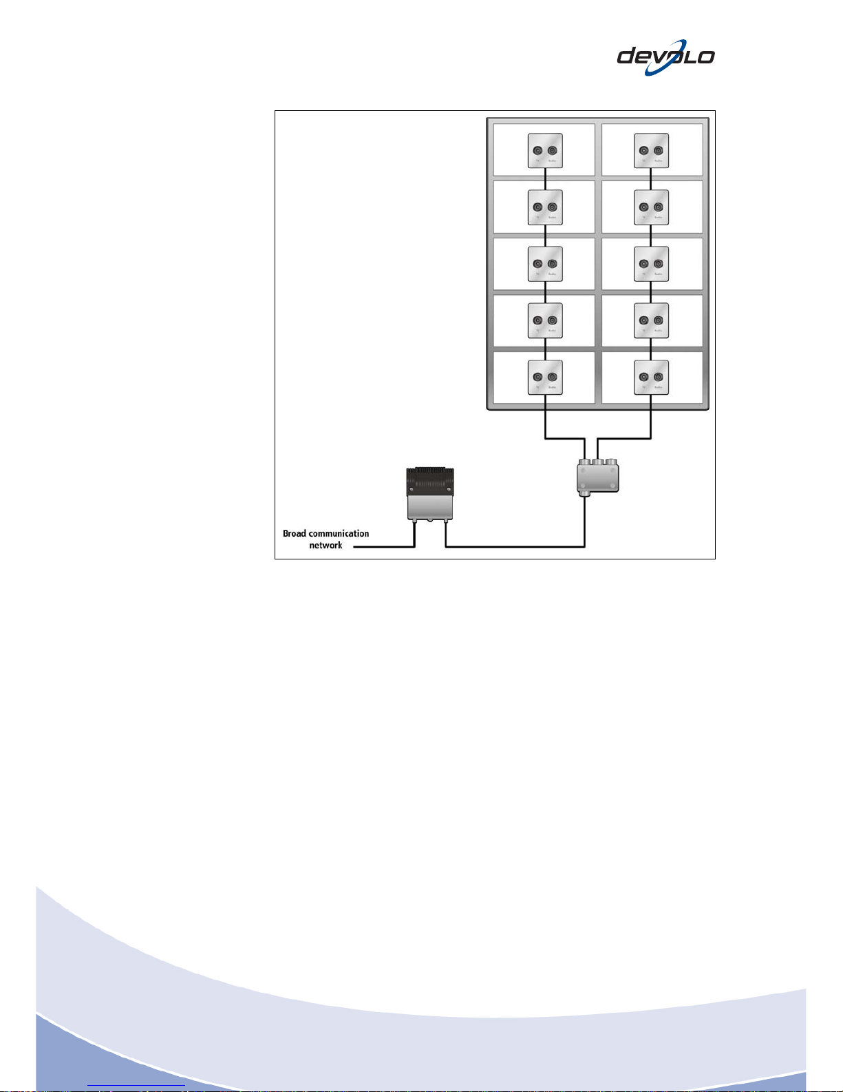
3.2 Network types.................................................................................................................................5
3.3 Installed components ......................................................................................................................8
3.3.1 Antenna outlets (wall)............................................................................................................9
3.3.2 Splitter/Tap ..........................................................................................................................10
3.4 Back-channel compatibility, a DOCSIS technology term ..................................................................11
3.5 The deployment of devolo dLAN technology in antenna networks ..................................................12
3.5.1 Coupling the Ethernet signal to the antenna cable ................................................................13
3.5.2 Tapping the Ethernet signal on the antenna socket............................................................... 14
3.5.3 Bypassing amplifiers (passive bypass) ...................................................................................15
3.5.4 Bypassing amplifiers (active bypass)...................................................................................... 16
3.5.5 Bypassing amplifiers (passive return path on the amplifier)....................................................17
3.5.6 Using filters (high pass)........................................................................................................17
3.5.7 Logical segmentation ...........................................................................................................18
4Two-wire lines ............................................................................................................ 20
4.1 Twisted or untwisted pair, wire pair............................................................................................... 20
4.2 Point-to-point on telephone lines (available wire pair)....................................................................20
4.3 Point-to-point over telephone lines (occupied wire pair) ................................................................. 20
4.4 Point-to-multipoint on telephone lines (with telephone operation)..................................................21
4.5 BNC networks, 10Base2 networks.................................................................................................22
5Power lines ................................................................................................................. 23
5.1 Power supply systems in single-family homes.................................................................................23
5.2 Power supply systems in multiple dwelling units (centralised meter arrangement)...........................24
5.3 Power supply systems in multiple dwelling units (decentralised meter arrangement) .......................26
5.4 Power supply systems in large buildings......................................................................................... 26
5.5 Repeater circuits in power supply systems......................................................................................28
5.6 Segment insulation with EMI filters for repeater circuits .................................................................30
5.7 Phase coupling and residual current devices...................................................................................30
5.8 Sources of interference and remedies on the power line .................................................................31
5.9 Sinks and remedies on the power line............................................................................................32
6Projects ....................................................................................................................... 33

devolo dLAN® 200 AVpro Project Manual iii
6.1 Preparation...................................................................................................................................33
6.1.1 Questioning .........................................................................................................................33
6.1.2 Survey site ...........................................................................................................................35
6.1.3 Detailed planning, calculating the cost estimate.................................................................... 40
6.2 Implementation............................................................................................................................. 42
6.2.1 Preparing for the rollout .......................................................................................................42
6.2.2 Performing the rollout ..........................................................................................................43
6.3 Operation .....................................................................................................................................43
6.3.1 Management .......................................................................................................................43
6.3.2 Maintenance and support ....................................................................................................44
7Useful software........................................................................................................... 45
7.1 Iperf.............................................................................................................................................. 45
7.1.1 Application ..........................................................................................................................45
7.1.2 TCP or UDP.......................................................................................................................... 45
7.1.3 Setting up the server ............................................................................................................46
7.1.4 Setting up the client.............................................................................................................47
7.2 VLC ..............................................................................................................................................48
7.2.1 Application ..........................................................................................................................48
7.2.2 Streaming server/client.........................................................................................................49
7.2.3 Setting up the streaming server ............................................................................................49
7.2.4 Setting up the streaming client.............................................................................................51
8Annex .......................................................................................................................... 53
8.1 Sources for purchasing accessories ................................................................................................53

devolo dLAN® 200 AVpro Project Manual 1
1Introduction
This project manual aims to support you during the planning and installation of
devolo dLAN 200 AVpro products in projects on the basis of networks using coax-
line, twisted pair, or PowerLine connections. It addresses system integrators (e.g.
certified devolo partners, and other trained experts) that not only know the devolo
products, but also have skills in networking technology as well as in antenna
networks, electrical installations, and telephone networks.
The projects described in this manual have an average size of 20 endpoints. Please
keep in mind that even projects with only 5 endpoints can require quite complex
implementations. As a general rule, you can expect that projects with 20 endpoints
always require a careful preparation to avoid unpleasant surprises or time-
consuming reworks. However, the recommendations in this project manual are in
principle also applicable for projects consisting of hundreds of endpoints.
This manual should provide ideas for the organization and preparation of projects.
However, it makes no claim to completely or extensively describe all potential
options or alternatives for an implementation. According to experience, there are
usually different ways and methods to successfully realize a project. This project
manual aims to protect first-time users from typical errors, and, at the same time,
significantly reduce the learning curve for new projects.
For clarity reasons, we intentionally refrain from describing the functionality
and the technology of the equipment used for the implementation of the
different projects. If necessary, please consult the product’s documentation.
Please note that the figures in this manual show schematic views.
Depending on the producer of the different accessories (above all of diplex
filters), the type and, thus, the wiring can differ. The schematic views of the
diplex filters in this manual follow the products by Comega. You can find a
list of specific suppliers and circuit layouts on our website under
http://www.devolo.com/business/accessories-referencelist.html.
Without a doubt, the diversity of the different project scenarios, together with the
technical progress, will continue to pose a challenge for you and us. We will be
happy to resolve all potential problems together with you. Thus, it is very important
to us that we hear from your experiences and ideas, resulting from your project
implementations, using devolo products. Please send us your feedback under
[email protected]. You help us continuously improving our products, so that we can
better support you with your project realization.
Thank you!

devolo dLAN® 200 AVpro Project Manual 2
2Important basics
2.1 Attenuation
Coax networks, respectively signals that are transmitted via coax, experience an
attenuation effect, measured in dB (decibels). Each component and module on a
coax network has a specific amount of attenuation. If several components (splitters,
sockets, etc.) are installed in line, you can simply add the different attenuation
values.
Coax networks for TV transmission usually have an attenuation budget of 42 dB
behind the amplifier for the antenna signal. Thus, in practice all components behind
the antenna amplifier may only have a combined attenuation of 42 dB. Typically, a
well-implemented installation will never fully use the available attenuation budget.
An exceeded attenuation budget usually results in interferences in your TV
picture.
devolo dLAN 200 AVpro adapters provide an attenuation budget for the dLAN signal
of more than 60 dB. Thus, a dLAN data signal fed in behind the amplifier will still be
available at full capacity at the farthest socket. In terms of the cable length, you will
be able to bridge distances of up to 750 meters without loss using a dLAN signal on
a coax line.
2.2 Frequencies
Unlike antenna signals that are transmitted from sender to receiver in one direction
only (unidirectionally), the dLAN data transmission is bidirectional. The following
frequencies are used:
devolo dLAN AVpro adapters use a frequency range between 2 MHz and
30 MHz. Usually, this band will not be overlapped by antenna signals that use
frequencies of 85 MHz and up. It is rarely possible that frequencies over 47 MHz are
used to transmit antenna signals (the so-called band 1).
"Traditional" analogue TV signals are transmitted in a range up to 862 MHz.
Above and until 2400 MHz you can find the signals of the digital satellite
television.
The frequency band between 5 and 65 MHz (in Germany, other countries, like the
USA, use 50 MHz) is called feedback channel, because data is sent from the
endpoint to the provider, if DOCSIS cable modems are used. If the sub range
between 5 and 30 MHz is not used by other signals, it can be used to transmit data
using devolo dLAN adapters.
In rare and special applications (e.g. in pay-TV or minibar systems in hotels)
control signals are transmitted in the frequency range between 5 and 30 Mhz. If the
feedback channel is reserved for a signal (e.g. by a pay-TV system) a coexistence of
both services is usually still possible. For that purpose, the specific frequencies have

devolo dLAN® 200 AVpro Project Manual 3
to be notched out from the dLAN communication by configuration with the dLAN
AVpro manager.
Fig. 2-1: The devolo dLAN frequency range
For residential installations, these kinds of special installations are normally not
used. However, always clarify first, if a DOCSIS signal is decoupled on network layer
4 (area between the house transfer point and the line terminator (wall socket)) in the
appropriate segments. If the frequency range between 5 and 30 MHz is free from
any signals, a dLAN network can be implemented.

devolo dLAN® 200 AVpro Project Manual 4
3Antenna networks
Antenna or coax networks are typically organized in one of the following structures:
Star structure
Tree structure, or
Combinations of the two above mentioned structures.
In Germany, the tree structure is by far the most popular network type, as it is easy
to install and requires the least amount of cable.
Please note that the figures in this manual show schematic views.
Depending on the producer of the different accessories (above all of diplex
filters), the type and, thus, the wiring can differ. The schematic views of the
diplex filters in this manual follow the products by Comega. You can find a
list of specific suppliers and circuit layouts on our website under
http://www.devolo.com/business/accessories-referencelist.html.
3.1 Network topologies
In a tree structure, you can usually find network branches with each 4 to 10
antenna sockets, distributing the TV signal to the different viewers. For the purpose
of an efficient supply by dLAN adapters, these branches can be combined to larger
segments. Here, multiple branches are fed by one dLAN adapter as the so-called
master.
Fig. 3-1: The tree structure
Star structures are typically used in networks designed for satellite reception. You
should always feed in the dLAN data signals via the terrestrial input of the
multiswitch. Please note that this input has to be back channel compatible, so that
the data can be sent back from the receiver to the transmitter (see also section 2.2 in
this project manual).

devolo dLAN® 200 AVpro Project Manual 5
Fig. 3-2: The star structure
Floor star distributions can often be found in hotels: a single line connects one
floor. From there it is split up into the different rooms.
Fig. 3-3: The floor star
3.2 Network types
BC tree networks (broadband communication) are often used for the distribution
of TV programs in metropolitan areas of Germany. Typically, the TV signals are
routed from a cable network provider via network level 3 to the in-premises of a
house, where they are amplified. Afterwards, they are fed into network layer 4 and
distributed to the different antenna sockets via a tree structure. However, there are
also BC networks that were designed or modified as a star structure. Please note
that you can use the dLAN technology on both network types (tree or star).

devolo dLAN® 200 AVpro Project Manual 6
Fig. 3-4: A BC tree network
Satellite multiswitch systems star networks, represent the standard method of
installation for satellite systems with multiple endpoints (2 to 50 as a rule), which
are frequently encountered in rural areas. The signals are routed from a multiswitch
to each terminal device (e.g. satellite receiver) via dedicated lines in star-shaped
distribution. Frequently, an Ethernet connection can be coupled to a dLAN over what
is referred to as terrestrial input. You need to make sure that the terrestrial input is
passive, and equipped for transmitting a 5 MHz to 65 MHz frequency band. The
multiswitch system can possibly be switched over or retrofitted. As an alternative,
each of the subscribers can be coupled to a device pair (master/slave) behind the
multiswitch.

devolo dLAN® 200 AVpro Project Manual 7
Fig. 3-5: A sat multiswitch star network
Sat head-end tree networks are similar to broad communication network:
certain stations broadcast by satellites are converted on one channel in the
broadband communications network. The number of channels here is limited by the
frequency band available. Due to the high bandwidth required by each channel,
converting all signals broadcast via satellite is not possible. Frequently, these systems
are deployed where the a number of endpoints is > 100 (typically, from 300 to
several thousand). As a rule, these types of installations are found in hotels.

devolo dLAN® 200 AVpro Project Manual 8
Fig. 3-6: A sat head-end tree network
3.3 Installed components
When planning a project, it is important to have exact information on the installed
components. As a rule, detailed product sheets or specifications (on attenuation) are
available on the components in coaxial networks. Use of this information to the best
effect!
dLAN technology is largely compatible with all existing components installed. As a
result, is it only necessary to replace individual passive components in an antenna
system at network level 4 in very rare cases. Even obsolete components and cheap
cables with poor shielding can usually be reused. The list below is designed to
provide you with an overview of the components you will typically encounter and
their suitability:

devolo dLAN® 200 AVpro Project Manual 9
3.3.1 Antenna outlets (wall)
1) Antenna outlet as pass-through outlet (two connections)
Technical data:
Designation 1: pass-through attenuation 11 dB to 20 dB
Designation 2: pass-through attenuation 1.5 dB to 3 dB
Shielding requirements: > 80 dB
a) Option: broadband
5 MHz to 862 MHz: television
5 MHz to 862 MHz: radio
This option is suitable.
b) Option: selective
87.5 MHz to 108 MHz: VHF radio
118 MHz to 862 MHz: television
This option is unsuitable!
2) Antenna outlet (two connections)
Technical data:
Designation 1: pass-through attenuation approx. 4 dB
Shielding requirements: > 80 dB
a) Option: broadband
5 MHz to 862 MHz: television
5 MHz to 862 MHz: radio
This option is suitable.
Option: selective (is rarely installed)
87.5 MHz to 108 MHz: VHF radio
118 MHz to 862 MHz: television
This option is unsuitable!
3) Modem antenna outlet as pass-through outlet (two connections)
Technical data:
Designation 1: pass-through attenuation 11 dB to 20 dB
Designation 2: Pass-through attenuation 1.5 dB to 3 dB
Shielding requirements: > 80 dB
a) Option: broadband
5 MHz to 65 MHz (= modem): devolo dLAN 200 AVpro

devolo dLAN® 200 AVpro Project Manual 10
5 MHz to 862 MHz: television
5 MHz to 862 MHz: radio
This option is suitable.
b) Option: selective
5 MHz to 65 MHz (= modem): devolo dLAN 200 AVpro
87.5 MHz to 108 MHz: VHF radio
118 MHz to 862 MHz: television
This option is suitable.
4) Modem antenna outlet (three connections)
Technical data:
Designation 1: pass-through attenuation approx. 4 dB
Shielding requirements: > 80 dB
a) Option: broadband
5 MHz to 65 MHz (= modem): connecting dLAN products
5 MHz to 862 MHz: television
5 MHz to 862 MHz: radio
This option is suitable.
b) Option: selective
5 MHz to 65 MHz (= modem): connecting dLAN products
87.5 MHz to 108 MHz: VHF radio
118 MHz to 862 MHz: television
This option is suitable.
3.3.2 Splitter/Tap
1) The 2x splitter
Technical data:
Designation 1: pass-through
Designation 2: decoupling
Pass-through attenuation: 3,5 dB
Decoupling attenuation: > 22 dB
Shielding requirements: > 80 dB
This option is suitable.

devolo dLAN® 200 AVpro Project Manual 11
Only use the splitter in the pass-through direction, from input to output (1),
and not between outputs, since very high attenuation (> 22 dB) exists
between the outputs (2).
2) 2x tap
Designation 1: branch
Designation 2: pass-through
Designation 3: decoupling
Branch attenuation: 10 dB to 20 dB
pass-through: 1 dB to 3 dB
decoupling: 30 dB to 50 dB
Shielding requirements: > 80 dB
This option is suitable.
Only use the tap in the pass-through direction, from input to output (1, 2),
and not between outputs (3), since very high attenuation (> 30 dB) exists
between the outputs.
3.4 Back-channel compatibility, a DOCSIS technology term
The 5 MHz and 65 MHz frequency band in Germany (in other countries such as the
USA, 50 MHz) is frequently referred to as the "back channel," since it is used in
DOCSIS cable modem technology to transport the data from the endpoint back to
the provider (i.e. back = back channel). To deploy DOCSIS technology, antenna
networks are frequently converted at great expense to make them back channel-
compatible. This not only means that tree structures need to be converted into star
structures for DOCSIS operation, but that multimedia socket outlets also have to be
used all the time.
All this expense, which, in some cases, costs between 200 and 300 Euros per
housing unit [HU], is unnecessary when you deploy dLAN technology. Neither
converting to a star structure, nor multimedia socket outlets, are necessary for
deploying devolo dLAN technology. Nevertheless, its existence has no negative effect
on the sue of dLAN technology.
Antenna amplifiers represent a special case if the sections to be supplied are even
fitted with them. If they are, you also have the option of bypassing them (see
section 3.5.4).
Reference is frequently made to noise factors in this relation, and is often referred to
collectively as ingress. Ingress refers to electromagnetic interference caused in
coaxial by transmitters, household appliances, switched-mode power supply units
etc. Interference mainly occurs when the cable or its screening is damaged, plug-in
connections are faulty (or poorly screened), or the shielding requirement on the cable
is too low. In contrast to DOCSIS-based solutions, dLAN-Technology is highly
resilient to ingress.

devolo dLAN® 200 AVpro Project Manual 12
3.5 The deployment of devolo dLAN technology in antenna
networks
devolo dLAN 200 AVpro technology transports data in 2 to 30 MHz frequency band.
TV or radio signals are not normally allocated to this frequency band in the antenna
network, and it can therefore be used for data traffic. You need to take account of
the fact that the signals are bidirectional here, whereas TV and radio signals only
move in one direction (downstream).
The network topology employed usually takes the form of a tree structure, and in
rarer cases, a star structure. Several endpoints (apartments, rooms etc.) are fitted to
each cable leg in a tree structure. Usually each cable leg has between 8 and 10
endpoints, otherwise the attenuation on the cable leg is too high.
Fig. 3-7: Typical tree structure configuration in an antenna network
Per endpoint, one devolo dLAN 200 AVpro adapter transmits the signals from the
antenna cable to the LAN. The data format complies with the Ethernet standard. A
devolo dLAN 200 AVpro adapter configured as a master converts the signals to
Ethernet at the base of each cable leg, and communicates with the Internet via a
switch (router, etc.). The individual segments are insulated against one other with
high-pass filters (see Section 3.5.7).

devolo dLAN® 200 AVpro Project Manual 13
3.5.1 Coupling the Ethernet signal to the antenna cable
The illustration filter below shows an example of coupling the devolo dLAN 200
AVpro signals onto the antenna cable on the main distribution (Master). This can be
achieved with a diplex filter (reverse path combiner). On the one hand, the high-pass
filter prevents signals radiating in the direction of the cable network operator, and,
on the other, it prevents neighbouring segments from "seeing" one another, and
hence sharing the bandwidth. using such as the filter ensures that each segment can
use the entire bandwidth. In the apartment or rooms (endpoint), the adapter is
usually connected via the radio or antenna socket (see Fig. 3.11 and Section 3.3.2).
Fig. 3-8: Coupling the signals in-premises with a diplex filter
Fig. 3-9: Antenna system before connecting the adaptor over the antenna outlets

devolo dLAN® 200 AVpro Project Manual 14
Fig. 3-10: Antenna system after connecting the adaptor over the antenna outlets
If the antenna distribution is connected to the local cable network, use a
high-pass filter at all times!
Warning! The low-pass filter supplied in delivery (standard accessory: Part
No. 69723) should to be connected to the output on the dLAN unit at all
times to filter out ripples and hence prevent interference in the frequency
range for radio and TV.
3.5.2 Tapping the Ethernet signal on the antenna socket
You can tap the endpoints on the antenna socket outlet's radio output, if equipped
with one. This ouput is usually not allocated and the radio signal is less sensitive to
attenuation. If already allocated or not fitted to the antenna socket, you need to use
an additional T-piece, which causes additional attenuation of some 3.5 dB. If
multimedia sockets (socket outlets with 2 outputs for TV and radio, and an
additional F-connector output for data) are to be installed onsite, attach the
endpoint to the said data output. If no bandwidth or only a very small symmetrical
bandwidth is displayed, antenna sockets equipped with frequency converters with a
frequency range above 47 MHz may be installed, whereas attenuation takes place
below this at 20 - 30 dB. cf. Section 3.3.1).
In each of these cases, we urgently recommend finding out the exact
component designation (e.g. ESD30) and researching the technical data on
the web. This will provide you with the frequency responses and
attenuation values.

devolo dLAN® 200 AVpro Project Manual 15
Warning! The low-pass filter supplied in delivery (standard accessory: Part
No. 69723) should be connected to the output on the dLAN unit at all
times to filter out ripples are hence prevent interference in the frequency
range for radio and TV.
Fig. 3-11: Tapping the Ethernet signal on the antenna socket
3.5.3 Bypassing amplifiers (passive bypass)
The bypass circuit (passive return path, bypass) bridges an amplifier. Make sure that
there is enough sufficient stop-band attenuation on the diplex filters (e.g. Comega,
Tratec) here. Frequently, they only have 35dB stop-band attenuation. This is why a
high-pass filter (> 50 dB stop-band attenuation) needs to be fitted in the direction of
amplifier's output and input.
Deploying diplex filters is favourable to the data connection's attenuation budget.
For TV, a pass-through attenuation of approx. 2 x 0.5 dB (diplex) + 2 x 0.8 dB (high-
pass) should be taken into account.
Fig. 3-12: Bypassing an amplifier with a passive bypass

devolo dLAN® 200 AVpro Project Manual 16
Fig. 3-13: Example configuration with actual components
Amplifier bypasses can also be cascaded. Take note of the attenuation budget for
the devolo dLAN 200 AVpro adapter. The following figure illustrates a 3-level
cascade. Note that the amplifiers are much further apart in reality than in the
illustration.
Fig. 3-14: 3-level amplifier cascade with passive bypass
3.5.4 Bypassing amplifiers (active bypass)
The amplifier is bypassed using two devolo dLAN 200 AVpro adapters and an
Ethernet cable. Make sure that there is enough stop-band attenuation on the diplex
filters (e.g. Comega, ) here. Frequently, they only have 35dB stop-band attenuation.
This is why a high-pass filter (> 50 dB stop-band attenuation) needs to be fitted in
the direction of amplifier's output and input. A separate logical network segment
begins/ends before and after the amplifier. For TV, a pass-through attenuation of
approx. 2 x 0.5 dB (diplex) + 2 x 0.8 dB (high-pass) should be taken into account.
Since the connection functions like a repeater, this configuration is
well-suited to bridging large distances.
Other manuals for dLAN 200 AVpro
4
Table of contents
Popular Gateway manuals by other brands

Compal Broadband Networks
Compal Broadband Networks CH6640E user guide

ZyXEL Communications
ZyXEL Communications ZyWALL USG Series Application notes

Peavey
Peavey CAB 16i manual

AudioCodes
AudioCodes MediaPack MP-40x series user manual

Inteno
Inteno DG150v2 installation guide

Siemens
Siemens Gigaset SE567 quick start guide