DeWalt X536 User manual

If you have questions or comments, contact us.
Si tiene dudas o comentarios, contáctenos.
1-855-971-1123
Instruction Manual
Manual de instrucciones
FormNo.769-26099A
(October 14, 2021)
X536, X548, X554
Zero-Turn Mower
Rear Wheel Drive Stand-On

ENGLISH
English (original instructions) 1
Español (traducido de las instrucciones originales) 29
© 2021 DEWALT. DEWALT® and GUARANTEED TOUGH® are registered trademarks of the DEWALT Industrial Tool Co., used under license. All rights reserved. The
yellow and black color scheme is a trademark for DEWALT Power Tools and Accessories.
© 2021 DEWALT. DEWALT® y GUARANTEED TOUGH son marcas registradas de DEWALT Industrial Tool Co. usadas bajo licencia. Todos los derechos reservados.
El esquema de color negro y amarillo es una marca registrada de DEWALT Power Tools and Accessories.

ENGLISH
3
Definitions: Safety Alert Symbols and Words
This instruction manual uses the following safety alert symbols and words to alert you to hazardous situations and your risk of personal injury or property damage.
DANGER: Indicates an imminently hazardous situation which, if not avoided, will result in death or seriousinjury.
WARNING: Indicates a potentially hazardous situation which, if not avoided, could result in death or seriousinjury.
CAUTION: Indicates a potentially hazardous situation which, if not avoided, may result in minor or moderateinjury.
(Used without word) Indicates a safety related message.
NOTICE: Indicates a practice not related to personal injury which, if not avoided, may result in propertydamage.
WARNING!Read and follow all safety rules and instructions
in this manual before attempting to operate this machine. Failure to comply
with these instructions may result in personal injury.
NOTE: This Operator's Manual covers several models. Features may vary by model. Not
all features in this manual are applicable to all models and the model depicted may differ
from yours.
If you have any questions or comments about this or any DeWALT tool, call us toll
free at: 1-855-971-1123.

ENGLISH
4
DANGER: This machine was built to be operated according to the safe
operation practices in this manual. As with any type of power equipment,
carelessness or error on the part of the operator can result in serious injury.
This machine is capable of amputating hands and feet and throwing
objects. Failure to observe the following safety instructions could result in
serious injury or death.
WARNING: CALIFORNIA PROPOSITION 65 - Engine exhaust, some of its
constituents, and certain vehicle components contain or emit chemicals
known to the State of California to cause cancer and birth defects or other
reproductive harm.
Battery posts, terminals, and related accessories contain lead and lead
compounds, chemicals known to the State of California to cause cancer and
reproductive harm. Wash hands after handling.
WARNING: This symbol points out important safety instructions which,
if not followed, could endanger the personal safety and/or property
of yourself and others. Read and follow all instructions in this manual
before attempting to operate this machine. Failure to comply with these
instructions may result in personal injury. When you see this symbol. HEED
ITS WARNING!
Training
1. Only allow operators who are responsible, trained, familiar with the instructions, and
physically capable to operate the mower.
2. Be familiar with the areas in which the mower is to be used. Walk all areas to be
mowed, evaluate slopes and other terrain and look for obstacles to be avoided to
ensure safe operation before mowing.
3. See the Practice Operation section of this manual for further instructions.
General Operation
1. Be familiar with all controls and their proper operation. Know how to stop the mower
and disengage the controls quickly.
2. Do not allow anyone to operate or maintain this mower who has not read the
manual. Never permit children under the age of 16 to operate this mower.
3. Do not remove any shields, guards, labels or safety devices. If a shield, guard, label or
safety device is damaged or does not function, repair or replace it before operating
the mower.
4. To help avoid blade contact or a thrown object injury, keep bystanders, helpers,
children and pets at least 75 feet (22.9 meters) from the mower while it is in
operation. Stop mower if anyone enters the area.
5. Thoroughly inspect the area where the equipment is to be used. Remove all stones,
sticks, wire, bones, toys, and other foreign objects that could be picked up and thrown
by the blade(s).Thrown objects can cause serious personal injury.
6. Evaluate the terrain to determine what accessories and attachments are needed to
properly and safely perform the job. Only use accessories and attachments approved
by the mower manufacturer.
7. Plan mowing pattern to avoid discharge of material toward roads, sidewalks,
bystanders and the like. Also, avoid discharging material against a wall or obstruction
which may cause discharged material to ricochet back toward the operator.
8. Always wear appropriate clothing and personal protective equipment (e.g. safety
glasses, long pants, gloves, hearing protection , safety shoes, hard hat) when
operating or maintaining this mower. Long hair, loose fitting clothing or jewelry may
get entangled in moving parts. Follow all federal, state and local guidelines regarding
the use of personal protective equipment.
9. For extended use of this product, hearing protection is recommended.
10. Be aware of the mower and attachment discharge direction and do not point it
at anyone. Do not operate the mower without the discharge cover or entire grass
catcher in its proper place.
11. Do not put hands or feet near rotating parts or under the cutting deck. Contact with
the blade(s) can amputate hands and feet.
12. A missing or damaged discharge cover can cause blade contact or thrown
object injuries.
13. Stop the blade(s) when crossing gravel drives, walks, or roads and while not
cutting grass.
14. Watch for traffic when operating near or crossing roadways.This mower is not
intended for use on any public roadway.
15. Do not operate the mower while under the influence of alcohol or drugs.
16. Mow only in daylight or good artificial light.
17. Never carry passengers.
18. Back up slowly. Always look down and behind before and while backing to avoid a
back-over accident.
19. Slow down before turning. Operate the mower smoothly. Avoid erratic operation and
excessive speed. Be aware of the direction of travel to avoid accidents.
20. Disengage blade(s), set parking brake, stop engine and wait until the blade(s) come
to a complete stop before removing grass catcher, emptying grass, unclogging chute,
removing any grass or debris, or making any adjustments.
21. Never leave a running mower unattended. Always stop on level ground, turn off
blade(s), place drive speed control levers in neutral, set parking brake, stop engine
and remove key before leaving the operator position.
22. Use extra care when loading or unloading the mower on a trailer. The mower should
not be driven on unstable, unsecured or inadequate ramps because the mower could
tip over causing serious personal injury.
23. Check overhead clearances carefully before driving under low hanging tree branches,
wires, door openings etc., where the operator may be struck which could result in
serious injury.
24. Muffler and engine become hot and can cause a burn. Do not touch.
25. Disengage the blades, set the parking brake to the‘on’position and make sure the
speed control levers are in the neutral position before attempting to start the engine.
Only start the engine from the operator’s position.
26. Do not attempt to mow unusually tall, dry grass (e.g., pasture) or piles of dry leaves.
Dry grass or leaves may contact the engine exhaust and/or build up on the mower
deck presenting a potential fire hazard.
27. Do not stop or park the mower over dry leaves, grass, debris or other
combustible material.
28. Never attempt to operate the mower without the mowing deck attached; the mower
could tip over.
29. Keep the mower and especially the engine exhaust system and hydraulic
components clean and free of grease, grass and leaves to reduce the potential for
overheating and fire.
30. Allow the mower to cool at least 5 minutes before storing.
31. Use only accessories and attachments approved for this mower by the mower
manufacturer. Read, understand and follow all instructions provided with the
approved accessory or attachment.
32. Data indicates that operators, age 65 years and above, are involved in a large
percentage of riding mower-related injuries. Operators should evaluate their ability
to operate this mower safely enough to protect themselves and others from serious
injury.
33. Do not operate or start mower if there is fuel or oil leaks; repair immediately.
34. When looking for oil leaks, never run hands over hydraulic hoses, lines or fittings.
Never tighten or adjust hydraulic hoses, lines or fittings while the system is under
pressure. If high-pressure oil penetrates the skin seek immediate medical attention or
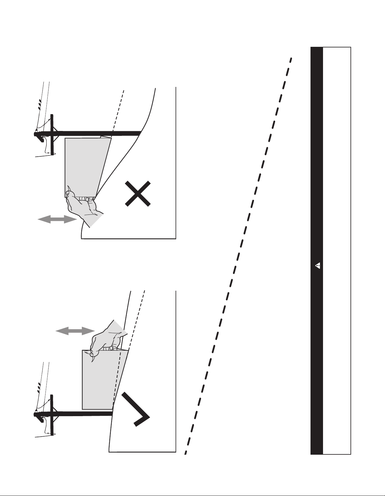
gangrene and permanent damage may result. Do not check for hydraulic leaks with
hands, use paper or cardboard instead.Wear gloves and safety glasses when checking
for leaks.
35. Do not operate mowers that have been damaged or have not been properly
maintained. If the mower has been damaged, then have it repaired.
36. When operating this mower in the forward direction, do not allow the speed control
levers to return to the neutral position on their own. Always operate them smoothly
and avoid any sudden movements of the levers when starting or stopping.
37. If situations occur which are not covered in this manual use care and good
judgement. Contact the customer service representative for assistance.
Slope Operation
Slopes are a major factor related to loss of control and tip-over accidents that can result in
severe injury or death. All slopes require extra caution. If you cannot back up the slope or
if you feel uneasy on it, do not mow it or drive on the slope.
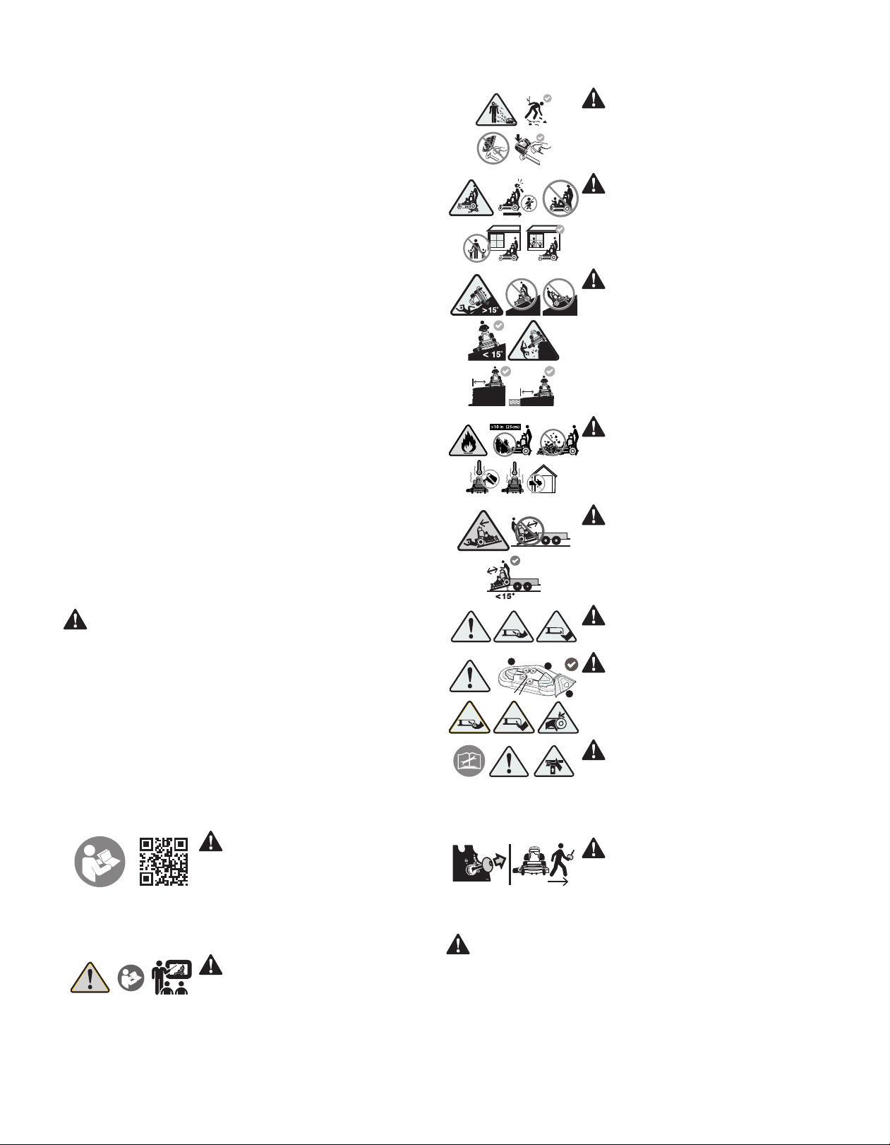
For your safety, use the slope gauge included as part of this manual to measure slopes
before operating this mower on a sloped or hilly area. If the slope is greater than 15
degrees as shown on the slope gauge, do not operate this mower on that area or serious
injury could result.
Do:
1. Mow across slopes, not up and down. Exercise extreme caution when changing
direction on slopes.
2. Watch for holes, ruts, bumps, rocks, or other hidden objects. Uneven terrain could
overturn the mower. Tall grass can hide obstacles.
3. Use slow speed. Choose a low enough speed so that the mower will not have to
stop while on the slope. Avoid starting or stopping on a slope. If the tires are unable
to maintain traction, disengage the blades and proceed slowly and carefully straight
down the slope.
SAFE OPERATION PRACTICES

ENGLISH
5
4. Keep all movements on the slopes slow and gradual. Do not make sudden changes in
speed or direction. Rapid acceleration could cause the front of the mower to lift and
rapidly flip over backwards, which could cause serious injury or death.
5. Follow the manufacturer’s recommendations for wheel weights or counterweights to
improve stability.
6. Use extra care with grass catchers or other attachments.These can change the
stability of the mower.
Do Not:
1. Do not turn on slopes unless necessary; then turn slowly uphill and use extra care
while turning.
2. Do not mow near drop-offs, ditches or embankments.The mower could suddenly turn
over if a wheel is over the edge of a cliff, ditch, or if an edge caves in.
3. Do not operate on slopes or near the edge of water such as a lake, pond, river or
stream where the mower could slip, tip or roll-over into the water.
4. Do not try to stabilize the mower by putting a foot on the ground.
5. Do not use a grass catcher on slopes steeper than 15 degrees.
6. Do not mow on wet grass. Reduced traction could cause sliding and/or loss
of control.
WARNING: Do not mow up and down the slope. You could slip and slide into
the mower, or the mower could lose traction and steering control.
Children
1. Tragic accidents can occur if the operator is not alert to the presence of children.
Children are often attracted to the mower and the mowing activity. They do not
understand the dangers. Never assume that children will remain where you last
saw them.
a. Keep children out of the mowing area and in watchful care of a responsible adult
other than the operator.
b. Be alert and turn mower off if a child enters the area.
c. Always look behind and down for small children. Use slow speed.
d. Never carry children, even with the blade(s) shut off.They may fall off and be
seriously injured or interfere with safe mower operation.
e. Use extreme care when approaching blind corners, doorways, shrubs, trees
or other objects that may block vision of a child who may run into the path of
the mower.
f. To avoid back-over accidents, always disengage blades before traveling in reverse.
g. Keep children away from hot or running engines.They can suffer burns from a hot
muffler.
h. Remove key when mower is unattended to prevent unauthorized operation.
2. Never allow children under 16 years of age to operate this tractor. Children 16 and
over should read and understand the instructions and safe operation practices in this
manual and on the tractor and should be trained and supervised by an adult.
Transporting Mowers
1. This mower is not intended for use on public roads. Mowers operated on public roads
must comply with state & local ordinances, SAE J137, and ANSI/ASABE S279 (lighting
and marking requirements).
2. Use care when loading or unloading mowers onto trailers.
3. If ramps are used, they must be full width, stable, have an adequate capacity rating
and be secured to the trailer. Ramp angle should not exceed 15 degrees and trailer
should be parked on level terrain.
4. Mowers must be secured onto trailers with straps, chains, cables, ropes, or other
means deemed adequate for that purpose. The front and rear of the mowers must be
secured to the trailer in both the lateral and vertical directions.
5. Inspect the mower on a regular basis for damage and improper operation. Replace
all components that are damaged or are not functioning properly with authorized
replacement parts.
Hydraulic Devices & Systems
Hydraulic fluid escaping under pressure may have sufficient force to penetrate skin and to
cause serious injury. If foreign fluid is injected into the skin, it must be surgically removed
within a few hours by a doctor familiar with this form of injury, or gangrene may result.
WARNING: Keep body and hands away from pinholes or nozzles that could
eject hydraulic fluid under high pressure. Use paper or cardboard, not
hands, to search for leaks!
Safely relieve all pressure in the system before performing any work on the system, and
make sure that:
• The ignition switch is OFF
• The key is removed
• The engine spark plug wire(s) are removed
• All connections to the negative terminal of the battery are removed
• The park brake is set
• All by-pass valves, if so equipped, are open
• Hydraulic controls are actuated to release pressure on pumps, cylinders, etc. If“float”
positions are available, they should be used
After the above operations are completed, it should be safe to begin disconnecting the
lines or components. It is still a good idea to cover the connection with a cloth shield and
then gently loosen connections.
WARNING: Make sure all hydraulic fluid connections are tight and all
hydraulic hoses and lines are in good condition before applying pressure to
the system.
Service
Safe Handling of Gasoline:
1. To avoid personal injury or property damage use extreme care in handling fuel. Fuel
is extremely flammable and the vapors are explosive. Serious personal injury can
occur when fuel is spilled on yourself or your clothes which can ignite. Wash skin and
change closes immediately.
2. Use only approved containers.
3. Never fill containers inside a vehicle or a truck or trailer bed with a carpeted or plastic
liner. Always place containers on the ground away from vehicle before fueling.
4. When practical, remove mowers from the truck or trailer and refuel it on the ground. If
this is not possible, then refuel equipment on a trailer with a portable container rather
than from a fuel dispenser nozzle.
5. Keep nozzle in contact with the rim of the fuel tank or container opening at all times
until fueling is complete. Do not use a nozzle lock-open device.
6. Extinguish all cigarettes, cigars, pipes and other sources of ignition.
7. Never fuel mower indoors or near ignition sources.
8. Never remove fuel cap or add fuel while the engine is hot or running. Allow engine to
cool at least two minutes before refueling.
9. Never over fill fuel tank. Fill tank to no more than ½ inch below bottom of filler neck
to allow space for expansion.
10. If necessary, use a funnel to avoid spillage.
11. Replace fuel cap and tighten securely.
12. If fuel is spilled, wipe off the engine and equipment.Wait 5 minutes before starting
the engine.
13. To reduce fire hazards, keep mower free of grass, leaves, or other debris build-up.
Clean up oil and fuel spillage and remove any fuel soaked debris.
14. Never store the mower or fuel container inside where there is an open flame, spark
or pilot light as on a water heater, space heater, furnace, clothes dryer or other
gas appliance.
General Service:
WARNING: Never let children or untrained people operate or service
this mower.
1. Never run an engine indoors or in a poorly ventilated area. Engine exhaust contains
carbon monoxide, an odorless, and deadly gas.
2. Before cleaning, repairing, or inspecting, make certain the blade(s) and all moving
parts have stopped. Disconnect the spark plug wires and remove the key from the
ignition to prevent unintended starting.
3. Periodically check to make sure the blades come to complete stop within
approximately (7) seven seconds after operating the blade disengagement control. If
the blades do not stop within this time frame, the mower should be serviced.
4. Never tamper with the safety interlock system or other safety devices.
5. Regularly check the safety interlock system for proper function, as described later
in this manual. If the safety interlock system does not function properly, have the
mower serviced.
6. Check brake operation frequently as it is subjected to wear during normal operation.
Adjust and service as required.
7. Check the blade(s) and engine mounting bolts at frequent intervals for proper
tightness. Also, visually inspect blade(s) for damage (e.g., excessive wear, bent,
cracked). Replace the blade(s) with the original equipment manufacturer’s (O.E.M.)
blade(s) only, listed in this manual.“Use of parts which do not meet the original
equipment specifications may lead to improper performance and compromise
safety!”
8. Mower blades are sharp. Wrap the blade or wear gloves, and use extra caution when
servicing them.
9. Keep all nuts, bolts, and screws tight to be sure the equipment is in safe working
condition.
SAFE OPERATION PRACTICES, cont'd

ENGLISH
6
10. After striking a foreign object (or if abnormal vibration occurs), stop the blades and
engine and thoroughly inspect the mower for any damage. Make necessary repairs
before resuming operation.
11. Never attempt to make adjustments or repairs to the mower while the engine
is running.
12. Grass catcher components and the discharge cover are subject to wear and
damage which could expose moving parts or allow objects to be thrown. For safety
protection, frequently check components and replace immediately with original
equipment manufacturer’s (O.E.M.) parts only, listed in this manual.“Use of parts
which do not meet the original equipment specifications may lead to improper
performance and compromise safety!”
13. Do not change the engine governor settings or over-speed the engine.The governor
controls the maximum safe operating speed of the engine.
14. Maintain or replace safety and instruction labels, as necessary.
15. Observe proper disposal laws and regulations for gas, oil, etc. to protect
the environment.
Do Not Modify Engine
To avoid serious injury or death, do not modify engine in any way. Tampering with the
governor setting can lead to a runaway engine and cause it to operate at unsafe speeds.
Never tamper with factory setting of engine governor.
Notice Regarding Emissions
This mower is equipped with an engine that is certified to federal EPA emission standards
for non-road engines and equipment, and where applicable to California Air Resources
Board (CARB) emission standards.The engine owner’s manual is supplied by the engine
manufacturer, and provides additional information relating to the emission system,
warranty, maintenance of the engine in accordance with EPA and/or CARB regulations.
Making any unauthorized alterations or modifications to the engine, fuel, or venting
systems may violate EPA and CARB regulations.
When required, models are equipped with low permeation fuel lines and fuel tanks for
evaporative emission control. California models may also include a carbon canister. Please
contact Customer Support for information regarding the evaporative emission control
configuration for your model.
This mower is designed to run on regular, unleaded gasoline, 87 octane or higher. Never
use gasoline containing methanol or gasoline containing more than 10% ethanol (i.e.,
E15 or E85 fuels) because the fuel system may be damaged.
Spark Arrestor
WARNING:
This machine is equipped with an internal combustion engine
and should not be used on or near any unimproved forest-covered, brush-
covered, or grass-covered land unless the engine’s exhaust system is
equipped with a spark arrestor meeting applicable local or state laws (if any).
If a spark arrestor is used, it should be maintained in effective working order by the
operator. In the State of California the above is required by law (Section 4442 of the
California Public Resources Code). Other states may have similar laws. Federal laws apply
on federal lands.
A spark arrestor for the muffler is available through your nearest engine authorized
service dealer or contact the service department, P.O. Box 361131, Cleveland,
Ohio 44136-0019.
Safety Symbols
This page depicts and describes safety symbols that may appear on this product. Read,
understand, and follow all instructions on the machine before attempting to assemble
and operate.
OPESymbol.com
WARNING- Read Operator’s Manual(s)
Read, understand and follow all the safety rules and instructions
in the manual(s) and on the mower before attempting to
operate this mower. Failure to comply with this information
may result in personal injury or death. Keep this manual in a
safe location for future and regular reference. Using a Smart
Phone, scan the QR code symbol to learn more information
concerning the warnings contained on this mower. You can also
go to www.OPESymbol.com for more information.
DANGER- Training
Read Operator’s Manual. Do not operate this mower unless you
are trained.
DANGER- Avoid Thrown Objects Injury
Keep helpers at least 75’ (23 meters) from mower during
operation. Remove all stones, sticks, wire, bones, toys, and
other foreign objects which could be picked up and thrown by
the blade(s). Do not operate the mower without the discharge
cover or entire grass catcher in its proper place.
DANGER- Avoid Child Backover/Runover/Blade Injury
To avoid back-over accidents, always look behind and down for
small children. Never carry children, even with the blade(s) shut
off. Keep bystanders, children and pets inside during operation
under the watchful care of a responsible adult other than the
operator. Stop mower if anyone enters the area.
>
10 ft (3 m)
>
10 ft (3 m)
DANGER- Avoid Tip-Over/Roll-Over Injury
Do not operate mower on a slope greater than 15° (25%). Do
not mow up or down slopes, only mow across slopes that are
less than 15 degrees (25%). Use low speeds and avoid sudden
turns on slopes. Stay at least 10 feet (3 meters) from drop-offs,
ditches, embankments or the edge of water.
WARNING- Avoid Fires
Your mower is designed to cut normal residential grass of a
height no more than 10” (25cm). Do not attempt to mow
through unusually tall, dry grass (e.g., pasture) or piles of dry
leaves. Allow a mower to cool at least five minutes before
fueling or storing inside an enclosed garage or storage shed.
DANGER- Avoid Transport Injury
Use care when loading and unloading mowers onto trailers.
DO NOT drive mower forward onto trailers. ALWAYS back
the mower onto trailers. Use full width ramp for loading and
unloading. Ramp angle should not exceed 15 degrees and trailer
should be parked on level terrain.
WARNING- Avoid Amputation Injury
Do not put hands or feet near or under the cutting deck. Contact
with the blade(s) can amputate hands and feet.
12
3
WARNING- Avoid Amputation Injury
Do not put hands or feet near rotating parts or under the cutting
deck. Contact with the blade(s) can amputate hands and feet.
Ensure that all safety devices (guards, shields, switches, etc.)
are in place and working. Belt and/or blade spindle contact can
crush or injury body parts.
WARNING- Avoid Crush/Pinch Point Injury
Read, understand and follow all the safety rules and instructions
in the manual(s) and on the mower before attempting to service
this mower. For foot lift models only, the deck lift system is
spring-assisted and under tension. Always use the provided
multi-tool to secure the lift system in the locked position before
attempting to remove the mower deck.
WARNING- Remove Key
Always turn off blade(s), move the drive control levers
outward into park position, stop engine and remove key
before dismounting. If you are leaving the mower unattended,
always remove the key to prevent unauthorized use by children
or others.
WARNING: Your Responsibility -Restrict the use of this power machine to
persons who read, understand, and follow the warnings and instructions in
this manual and on the machine. SAVE THESE INSTRUCTIONS!
SAFE OPERATION PRACTICES, cont'd

ENGLISH
7
(OK) (TOO STEEP)
USE THIS SLOPE GAUGE TO DETERMINE
IF A SLOPE ISTOO STEEP FOR SAFE OPERATION!
To check the slope, proceed as follows:
1. Remove this page and fold along the dashed line.
2. Locate a vertical object on or behind the slope (e.g. a pole, building, fence, tree, etc.)
3. Align either side of the slope gauge with the object (See Figure 1 and Figure 2 ).
4. Adjust gauge up or down until the left corner touches the slope (See Figure 1 and Figure 2).
5. If there is a gap below the gauge, the slope is too steep for safe operation (See Figure 2 above).
15°/25% dashed line
Slope Gauge
Figure 2Figure 1
15°/25% Slope
15°/25%
Slope
WARNING
Slopes are a major factor related to slip and fall accidents which can result in severe injury or death. All slopes require extra caution.
If you feel uneasy on the slope, do not mow it. Do not mow on slopes greater than 15 degrees (25%). Only mow across slopes, never
mow up and down slopes.
SLOPE GAUGE

ENGLISH
8
Thank You
IMPORTANT: This mower is shipped without gasoline in the engine. Be certain to
service engine with gasoline and check oil as instructed in the Operation section of the
Engine Manual before starting or operating the mower.
NOTE: References to LEFT, RIGHT, FRONT, and REAR indicate that position on the mower
when facing forward while standing on the operator’s platform.
Mower Preparation
TOOLS NEEDED: Safety glasses, leather gloves, wire cutters.
1. Remove the upper crating material from the shipping pallet, and cut any bands or tie
straps securing the mower to the pallet.
2. Use the deck lift handle (a) to raise the deck to the transport lock position (b) (highest
adjustment setting) and insert the clevis pin (c) into the highest mowing setting (d)
to secure the deck lift handle in place. See Figure 1.
(a)
(b)
(d)
(c)
Figure1
IMPORTANT: The mower is equipped with two hydrostatic transmissions. Each
transmission is equipped with a bypass valve that MUST be opened before manually
moving the mower.
3. Perform the following to open the two hydrostatic transmission bypass valves:
a. Loosen the two star knobs (e) securing the leg pad (f) to the mower. See Figure 2.
b. Remove the leg pad from the mower.
c. Remove the rear panel from the mower. Refer to Removing/Installing The Rear
Panel on page 8.
(e)
(f) (e)
Figure2
IMPORTANT: DO NOT open the bypass valves more than a maximum of two turns.
4. Locate the hydrostatic transmissions and open the two bypass valves (G) a maximum
of two turns. See Figure 3.
5. Reinstall the rear panel. Refer to Removing/Installing The Rear Panel on page 8.
6. Using the two star knobs, reinstall the leg pad.
(g)
Figure3
WARNING: Do not tow the mower, even with the bypass valves engaged.
Serious transmission damage will result from doing so.
7. Carefully roll the mower off the shipping pallet.
IMPORTANT: The bypass valves MUST be closed before operating the mower.
8. Reverse STEP 3 to close the two bypass valves.
9. To engage the parking brake, pull back completely on the parking brake lever (j) See
Figure 4.
(j)
Figure4
10. Cut any wire ties holding the chute deflector up and discard any packing material.
Removing/Installing The Rear Panel
NOTE: The rear panel is secured to the mower using two star knobs or two quarter turn
latches.
IMPORTANT: Ensure the mower is unoccupied with the engine off and parking break
engaged before performing this procedure.
Rear Panel With Star Knobs
1. Remove the two star knobs (a) securing the
rear panel (b) to the mower.
2. Remove the rear panel from the mower.
3. Reverse STEPS 1 - 2 to install the rear panel.
Rear Panel With Quarter Turn
Latches
1. Lift latch up and rotate the latch one 1/4 turn
and align the latch with the slot in the rear panel.
Repeat this step to the remaining latch.
2. Remove the rear panel from the mower.
3. Reverse STEPS 1 - 2 to install the rear panel.
Lubrication & Grease Points
Before operating the mower, refer to the Product Care section of this manual to check
the lubrication and grease points. Grease and lubricate if necessary.
Checking Tire Pressure
WARNING: For proper traction and deck leveling the maximum
recommended tire pressure is 12 psi. Equal tire pressure should be
maintained at all times. NEVER exceed the Maximum PSI noted on the tire
side wall.
Inflation Pressure
Rear Tires — 10-12 psi (69-82.7 kPa) max recommended operating pressure.
FrontTires — N/A - Front tires are semi pneumatic and do not require inflation.
The tires on the mower may be over-inflated for shipping purposes. Reduce the tire
pressure before operating the mower. Recommended operating tire pressure is 10-12 psi
(69-82.7 kPa) for rear tires.
(a)
(b)
(a)
(b)
1
2
ASSEMBLY

ENGLISH
9
ASSEMBLY, cont'd
Connecting the Battery Cables
WARNING: California PROPOSITION 65 Battery posts, terminals, and
related accessories contain lead and lead compounds, chemicals known to
the State of California to cause cancer and reproductive harm. Wash hands
after handling.
WARNING: When attaching battery cables, always connect the POSITIVE
(Red) wire to its terminal first, followed by the NEGATIVE (Black) wire.
For shipping reasons, both battery cables on your equipment may have been left
disconnected from the terminals at the factory.To connect the battery cables, proceed
as follows:
1. Release the two latches securing the battery cover (a) to the battery box (b) and
remove the battery box lid (c). See Figure 5.
(a)
(a)
(b)
(c)
Figure5
NOTE: The positive battery terminal is marked POS. (+) (d). The negative battery
terminal is marked NEG. (–) (e).
NOTE: If the positive battery cable (f) is already attached, skip ahead to step 4.
2. Remove the red boot (g), if present, from the positive battery terminal (d) and attach
the red cable (f) to the positive battery terminal (d) with the hex cap screw (h) and
sems nut (i).
(i)
(l) (e)
(d) (f) (g)
(h)
(k)
(j)
Figure6
3. Position the red boot (g) over the positive battery terminal (d) to insulate it and help
protect it from corrosion.
4. Attach the black cable (j) to the negative battery terminal (e) with the hex cap screw
(k) and sems nut (l).
5. Reverse STEP 1 to reinstall the battery cover to the battery box.
Note: If the battery is put into service after the date shown on top/side of battery,
charge the battery prior to operating the machine.
Battery Maintenance
• The battery is filled with battery acid and then sealed at the factory. However, even a
“maintenance free”battery requires some maintenance to ensure its proper life cycle.
• Spray the terminals and exposed wire with a battery terminal sealer, or coat the
terminals with a thin coat of grease or petroleum jelly, to protect against corrosion.
• Always keep the battery cables and terminals clean and free of corrosion.
• Avoid tipping. Even a sealed battery will leak electrolyte when tipped.
Battery Storage
• When storing the tractor for extended periods, disconnect the negative battery cable.
It is not necessary to remove the battery.
• All batteries discharge during storage. Keep the exterior of the battery clean,
especially the top. A dirty battery will discharge more rapidly.
• The battery must be stored with a full charge. A discharged battery can freeze sooner
than a charged battery. A fully charged battery will store longer in cold temperatures
than hot.
• Recharge the battery before returning to service. Although the tractor may start, the
engine charging system may not fully recharge the battery.
ADJUSTMENTS
Leg Pad Height
1. Loosen the two star knobs (a) securing the leg pad (b) to the mower. See Figure 7.
2. Remove the leg pad from the mower.
3. Reposition the leg pad into one of three height positions (c).
4. Using the two star knobs, secure the leg pad to the mower.
(a)
(b)
(a)
(c)
(c)
Figure7
Operator’s Platform Suspension (Mowers With 36 Inch Decks
Only)
The mower operator’s platform suspension firmness is adjustable. Moving the two
adjustment rods to one of four combinations (Figure 8 Inset) will provide a firmer or softer
operator’s platform suspension.
1. Remove the rear panel. Refer to Removing/InstallingThe Rear Panel on
page 8.
2. Locate the two adjustment rods (a).
NOTE: Refer to Figure 8 inset to see the stop position locations for the desired
suspension firmness.
3. Moving one adjustment rod at a time, slightly pull and lift the adjustment rod off of
the ball stud (b).
4. Push or pull the adjustment rod until the loop is over the correct ball stud for the
desired suspension firmness.
5. Lower the adjustment rod down until the loop is fully seated onto the stop post.
6. Repeat STEPS 4 - 5 to reposition the remaining adjustment rod if necessary.
Firm
Soft
or
(a)
(b)
Figure8

ENGLISH
10
NOTE: This Operator’s Manual covers several models. Mower features may vary by
model. Not all features in this manual are applicable to all mower models and the
mower depicted may differ from yours.
NOTE: References to LEFT, RIGHT, FRONT, and REAR indicate that position on the mower
when facing forward while standing on the operator’s platform.
Features
Drive Control Levers (A)
The RH (Right Hand) and LH (Left Hand) drive control levers are located on each side of
the control panel.
Each drive control lever controls the respective transmission. Consequently, these levers
control all of the mowers movement. Driving and steering using these control levers
is quite different from conventional mowers and will take practice to master. Refer to
Practice Operation section for further instructions.
Parking Brake Lever (B)
The parking brake lever is located to the left of the control panel. Pull
the parking brake lever back to engage the brake (ON position“ ”)
or push the parking brake lever forward to disengage the brake (OFF
position“ ”).
IMPORTANT: Parking Brake on 36 Inch Mowings Decks - Uses brake
wedges that will require adjustment as the rear wheel tire tread wears.
Refer to Parking Brake Check/Adjustment - 36 Inch Deck Only on
page 17.
Deck Lift Handle (C)
The deck lift handle is located on the right side of the mower, and is used to raise and
lower the mower deck.
Depress the button on the end of the handle and push downward to lower the deck, or
pull upward to raise the deck. When the desired height is attained, secure the pin in the
desired index hole and release the button on the handle.
NOTE: Make certain the deck is secured and the pin is fully inserted into the deck height
index. The pin is keyed to help keep it in place and fits into the slotted holes on the deck
height index.
NOTE: The deck lift handle must always be above the pin, never hang the deck lift
handle from the pin when mowing.
Deck Height Index (D)
The deck height index consists of several holes located on the right of the mower. Each
hole corresponds to a 1⁄4 inch (6.4 mm) change in the deck height position ranging
from 1 1/2 inch (38.1 mm) at the lowest setting to 4 1/2 inch (114.3 mm) at the highest
setting. Insert the connected pin to select the desired deck height.
Transport Lock (Not Shown) (E)
The transport lock is the highest setting on the deck height index, and is used to lock
the deck into the transport position. Use the deck lift handle to engage or disengage the
transport lock.
NOTE: Mowers with 48 or 54 inch Mowing Decks - Do not mow with the deck in the
transport position.
NOTE: Mowers with 36 inch Mowing Decks - The 4 1/2 inch (114.3 mm) mowing deck
height adjustment is used as the transport position and as the highest deck height for
mowing.
Fuel Cap (F)
Turn the fuel cap counter clockwise and pull upward to remove. The fuel cap is tethered
to the mower to prevent its loss. Do not attempt to remove the fuel cap from the mower.
Fill tank to 1/2”(12.7 mm) below the bottom of the filler neck, allowing some space in the
tank for fuel expansion. Do not overfill the tank.
Push the fuel cap downward on the fuel tank fill neck and turn clockwise until the cap
clicks at least two times to tighten. Always re-install the fuel cap tightly onto the fuel tank
after removing.
WARNING: Never fill the fuel tank when the engine is running. If the engine
is hot from recently running, allow to cool for at least five minutes before
refueling. Highly flammable gasoline could splash onto the engine and
cause a fire.
Fuel Gauge (If Equipped) (G)
There is a fuel gauge on top of the tank to the left of the operator’s platform.
MIL Light or Choke Knob (If Equipped) (H)
The Multifunction Indicator Light (MIL) (if equipped): Provides diagnostic
information for the engine. If the MIL lights up and/or flashes see the service manual or
contact your service centerChoke Knob (If equipped)
The Choke Knob (if equipped): Pull the knob out to choke the engine;
push the knob in/down to open the choke. Having the choke in the“ON”
position helps the engine to start during initial start-up. During normal
operation the choke should be“OFF”.
CHOKE
CONTROLS & OPERATION
G
FML
H
K
IJ
A
B
D
C
P
OM
R
S
Q
Figure9

ENGLISH
11
CONTROLS & OPERATION, cont'd
Throttle Control Lever (I)
NOTE: When set in a given position, a uniform engine speed will be maintained.
Throttle Control Lever - Push the throttle control lever forward to increase the engine
speed.The mower is designed to operate with the throttle control lever at full throttle
(FAST) when the mower is being driven and the mower deck is engaged. Pull the
throttle control lever rearward to decrease the engine speed (SLOW) .
Power Take-Off (PTO) Electric PTO (J)
The PTO switch operates the electric PTO clutch mounted on the bottom
of the engine crankshaft. Pull the switch knob upward to engage the PTO
clutch, or push the knob downward to disengage the clutch.
The PTO switch must be in the“OFF”position when starting the engine.
Ignition Switch (K)
WARNING: Never leave a running machine unattended. Always
disengage PTO, set parking brake, stop engine and remove key to prevent
unintended starting.
The ignition switch has three positions:
STOP —The engine and electrical system is turned off.
RUN — The riding mower electrical system is energized.
START — The starter motor will turn over the engine. Release the key immediately
when the engine starts, the key will automatically return to“Run”position.
Note: To prevent accidental starting and/or battery discharge, remove key from the
ignition switch when mower is not in use.
Hour Meter & LCD Service Minder (If Equipped) (L)
The LCD service minder will remind the
operator of maintenance intervals for
changing the engine oil, air filter service,
low engine oil and low battery warnings.
When the key is rotated out of the STOP
position but is not in the START position, the
LCD service minder & hour meter will briefly
display the battery voltage, followed by the
mower’s accumulated hours.
Note: When the ignition key is out of the STOP position the hourglass symbol is
illuminated/blinks to indicate it is recording the hours of mower operation, regardless of
whether the engine has been started.
• Change Oil - The LCD screen will alternate the letters“CHG”, followed by“OIL”, followed
by“SOON”, followed by the meter’s accumulated time.“CHG/OIL/SOON/TIME”will
alternate on the display for 7 minutes after the meter reaches 50 hours. This oil service
minder interval will occur every 50 hours. Before the interval expires, change the
engine oil as instructed in the Engine Operator’s Manual
• Low Oil -The LCD screen will alternate the letters“LO”followed by“OIL”, followed by
the meter’s accumulated time, which indicates the engine has low oil pressure.This
is common when starting an engine. The indicator will remain active until the engine
sufficiently builds pressure after starting. If it remains on with the engine at full speed
and after a few minutes of operation, stop the mower immediately and check the
engine oil level and add as instructed in the Engine Operator’s Manual. If the oil level
is correct and the indicator persists, contact an authorized service dealer.
NOTE: The low oil pressure function only works if the engine is equipped with an oil
pressure switch.
• Low Battery - At startup, the battery voltage will briefly display, then changes
to accumulated hours. The letters“LO”followed by the letters“BATT”will display,
followed by the meter’s accumulated time.“LO/BATT/TIME”is displayed on the LCD
when the voltage drops below 11.5 volts.When this occurs, the battery is in need
of a charge or the engine’s charging system is not generating sufficient amperage.
Charge the battery as instructed in the Product Care section of this manual or have
the charging system checked by your local service dealer.
• Air Filter Service - The LCD screen will display the letters“CLN”followed by the letters
“AIR”, followed by“FILT”, followed by the meter’s accumulated time.“CLN/AIR/FILT/
TIME”will alternate on the display for 7 minutes after the meter reaches 25 hours.
This air filter service minder time interval will be every 25 hours. On intervals that are
common with oil service, the oil message will be displayed first followed by the air
filter message.
Accessory Switch/Power Bagger Assist/12 Volt Accessories
Receptacles (M)
The receptacles for optional accessories are on the control panel and right side of mower.
The receptacles are for a 12 volt outlet and head light.
Headlights (Not Shown/If Equipped) (N)
The headlight located in front of the control panel.The headlights are ON whenever the
ignition key is rotated out of the STOP position and OFF when the ignition key is moved
to the STOP position.
Leg Pad (O)
The leg pad is located in front of the operator’s position to provide a cushion between the
operator and the mower. Refer to the Adjustments section for instructions on adjusting
the leg pad position.
Operator’s Platform (P)
The operator’s platform is at the rear of the mower.
Suspension Adjustment Rods (If Equipped) (Q)
The mower operator’s platform suspension firmness is adjustable. Moving the two
adjustment rods to one of four combinations (insert FIGURE) will provide a firmer or softer
operator’s platform suspension.
Transmission Bypass valves(R)
The transmission bypass valves are located on the RH and LHTransmission (one for each
transmission). When in use, the two valves open a bypass within the hydrostatic
transmissions, which allows the mower to be pushed short distances by hand. Refer to
the Assembly section for additional instructions.
CAUTION: Never tow the mower. Towing the mower with the rear wheels on
the ground may cause severe damage to the hydrostatic transmissions
Hydrostatic Transmission Oil Reservoir (S)
The hydrostatic transmission oil reservoir is connected by hoses to the RH and LH
transmission assemblies, and is located behind the access panel in front of the
operator’s platform.
NOTE: Prior to the initial operation of the mower, check the hydrostatic transmission oil
level. Refer to Checking the Hydrostatic Transmission Oil Level on page 18.
Before OperatingYour Machine
1. Before you operate the mower, study this manual carefully to familiarize yourself with
the operation of all the instruments and controls. It has been prepared to help you
operate and maintain your machine efficiently.
2. Fill the fuel tank with only clean, fresh, unleaded gasoline with a pump sticker octane
rating of 87 or higher. When the fuel reaches 1⁄2”(12.7 mm) below the bottom of the
fill neck, stop. DO NOT OVERFILL. Space must be left for expansion.
• This engine is certified to operate only on clean, fresh, unleaded gasoline. Fill
only with clean, fresh, unleaded gasoline with a pump sticker octane rating of
87 or higher.
• Do not use gasoline left over from the previous season, to minimize gum
deposits in the fuel system.
• Gasohol (up to 10% ethyl alcohol, 90% unleaded gasoline by volume) is an
approved fuel. Other gasoline/alcohol blends are not approved.
• Methyl Tertiary Butyl Ether (MTBE) and unleaded gasoline blends (up to a
maximum of 15% MTBE by volume) are approved fuels. Other gasoline/ether
blends are not approved.
3. Check the engine oil level as instructed in the Engine Operator’s manual.
4. Check the hydrostatic transmission oil level. Refer to Checking The Hydrostatic
Transmission Oil Level in the Product Care Section.
5. Check the rear tire inflation pressure is 10-12 psi (69-82.7 kPa).
NOTE: New tires are over-inflated in order to properly seat the bead to the rim.
6. Check that all nuts, bolts and screws are tight.
7. Check the tension of the deck drive belts.
a. Remove the deck cover
b. The tension of the deck drive belts are maintained by a spring mechanism that
adjusts for wear and stretch.
c. Examine the belts for cuts, fraying, and excessive wear. Replace if any of these
are detected.
d. Replace the deck cover.
8. Check if deck is level.When correctly adjusted the mower deck should be level side to
side, and the front of the deck should be approximately 1⁄4”(6.4 mm) lower than the
rear of deck. If deck needs to be leveled, refer to the Service section.
9. Lubricate all pivot points listed in the Service section.
10. Adjust the leg pad and operator’s platform suspension (36 Inch Deck Only)for
operator’s maximum comfort, visibility and for maintaining complete control of the
machine. Refer to the Assembly & Set-Up section for instructions on adjusting the leg
pad and suspension.

ENGLISH
12
Safety Interlock System
WARNING: Do not operate the mower if the safety interlock system is
malfunctioning. This system was designed for your safety and protection.
This mower is equipped with a safety interlock system for the protection of the operator.
If the interlock system should ever malfunction, do not operate the mower. Contact an
authorized service dealer.
• The safety interlock system prevents the engine from cranking or starting unless the
parking brake is engaged, and the PTO lever is in the DISENGAGED (OFF) position.
• The engine will automatically shut OFF if the operator leaves the operator’s platform
before engaging the parking brake.
• The PTO will automatically shut OFF if the operator leaves the operator’s platform
with the PTO switch in the ENGAGED (ON) position, regardless of whether the parking
brake is engaged.
NOTE: The PTO must be disengaged to restart the engine.
Standing on The Operator’s Platform
WARNING: Only one person at a time may occupy the operator’s platform -
Otherwise injury may occur.
NOTE: Stepping off of the operator’s platform without engaging the parking brake will
cause the safety interlock system to stop the engine.
When standing on the operator’s platform:
• Do not turnaround or face away from the controls.
• When operating the mower, lean forward into the leg pad.
NOTE: The operator’s platform is equipped with an adjustable leg pad. If necessary,
adjust the leg pad height. Refer to Adjustments, Leg Pad Height in the Assembly &
Set-Up section.
Starting the Engine
WARNING: This machine is equipped with a safety interlock system designed
for protection of the operator. Do not operate the machine if any part of the
interlock system is malfunctioning. Periodically check the functions of the
interlock system for proper operation.
WARNING: For personal safety, the operator must be standing on the
operator’s platform when starting the engine.
1. Operator must be standing on the operator’s platform with both drive control levers
in the neutral/start position.
2. Engage the parking brake.
3. Make certain the PTO is in the disengaged (down) position.
4. Lift the choke knob (if equipped) into the ON position.
NOTE: If the engine is warmed up, it may not be necessary to choke the engine.
5. Move the throttle control to midway between the SLOW and FAST
positions.
6. Turn the ignition key clockwise to the START position and release it as soon as
the engine starts; however, do not crank the engine continuously for more than 5
seconds at a time. If the engine does not start within this time, turn the key to OFF
and wait at least 30 seconds to allow the engine’s starter motor to cool.Try again after
waiting. If after a few attempts the engine fails to start, do not keep trying to start it
with the choke closed as this will cause flooding and make starting more difficult.
7. Once the engine starts, push the choke (if equipped) halfway down and as the engine
warms, push the choke all the way down.
Cold Weather Starting
When starting the engine at temperatures near or below freezing, ensure the correct
viscosity motor oil is used in the engine and the battery is fully charged. Start the engine
as follows:
1. Be sure the battery is in good condition. A warm battery has much more starting
capacity than a cold battery.
2. Use fresh winter grade fuel.Winter grade gasoline has higher volatility to improve
starting. Do not use gasoline left over from summer.
3. Follow the previous instruction for Starting the Engine.
Using Jumper Cables To Start Engine
WARNING: Batteries contain sulfuric acid and produce explosive gasses.
Make certain the area is well ventilated, wear gloves and eye protection,
and avoid sparks or flames near the battery.
If the battery charge is not sufficient to crank the engine, recharge the battery. If a battery
charger is unavailable and the mower must be started, the aid of a booster battery will
be necessary. Connect the booster battery as follows:
1. Connect the end of one cable to the disabled mower battery’s positive terminal; then
connect the other end of that cable to the booster battery’s positive terminal.
2. Connect one end of the other cable to the booster battery’s negative terminal; then
connect the other end of that cable to the frame of the disabled mower, as far from
the battery as possible.
3. Start the disabled mower following the normal starting instructions previously
provided; then disconnect the jumper cables in the exact reverse order of
their connection.
4. Have the mower’s electrical system checked and repaired as soon as possible to
eliminate the need for jump starting.
Stopping the Engine
1. Move the RH and LH drive control levers neutral position.
2. Engage the parking brake.
3. Disengage the PTO.
4. Move the throttle control to the SLOW position.
5. Allow the engine to run for one minute then turn the key to STOP and remove
the from the ignition module.
NOTE: Always remove the key from the ignition module to prevent accidental
starting or battery discharge if the equipment is left unattended.
Practice Operation (Initial Use)
Operating a zero-turn mower is not like operating a conventional type riding mower.
Although and because a zero turn mower is more maneuverable, getting used to
operating the drive control levers takes some practice.
It is strongly recommended that you locate a reasonably large, level and open“practice
area”where there are no obstructions, pedestrians, or animals. You should practice
operating the mower for a minimum of 30 minutes.
Carefully move (or have moved) the mower to the practice area. When performing the
practice session, the PTO should not be engaged. While practicing, operate the mower at
approximately 1⁄2-3⁄4 throttle and at less than full speed in both forward and reverse.
Carefully practice maneuvering the mower using the instructions in the following
procedure Driving the Mower. Practice until you are confident that you can safely
operate the mower.
Driving the Mower
WARNING: Keep all movement of the drive control levers slow and smooth.
Abrupt movement of the control levers can affect the stability of the mower
and could cause the mower to flip over, which may result in serious injury or
death to the operator.
1. Ensure the RH and LH drive control levers are in the neutral position and the parking
brake is disengaged. See Figure 10.
NOTE: If the drive control levers are not even in the neutral position, refer to Product
Care for instructions to adjust the drive control levers so that they are even.
2. Move the throttle to the full throttle position.
WARNING: Always maintain a firm grip on the control levers. DO NOT
release the control levers to slow or stop the mower; move levers to neutral
position using your hands.
3. To drive the mower, firmly grasp the respective drive control levers with your right
and left hands.
Driving the Mower Forward
1. Slowly and evenly move both drive
control levers forward. The mower
will start to move forward. See
Figure 10.
2. As the drive control levers are
pushed farther forward the speed
of the mower will increase.
3. To slow the mower move the drive
controls lever rearward to attain
the desired speed, or move the
drive control levers to the neutral
position to stop the mower.
Driving Forward Faster
Slower
Neutral Position
Figure10
CONTROLS & OPERATION, cont'd

ENGLISH
13
Turning the Mower While Driving Forward
WARNING: Sharp turns can affect control of the mower. ALWAYS slow the
mower before making sharp turns.
To turn the mower while driving
forward, move the drive control levers
as necessary so that one drive control
lever is rearward of the other. The
mower will turn in the direction of the
rearward drive control lever.
1. To turn to the right, move the right
drive control lever rearward of the
left lever. See Figure 11.
2. To turn to the left, move the left
drive control lever rearward of
the right drive control lever. See
Figure 11.
3. The greater the distance between
the two levers, the sharper the
mower will turn.
4. To execute a“pivot turn,”move the
turn side drive control lever to the
neutral position, while moving the
other control lever forward.
NOTE: Making a “pivot turn” on grass will greatly increase the potential for
defacement of the turf.
Driving the Mower In Reverse .
WARNING: Always look behind and down on both sides of the mower before
backing up. Always look behind while traveling in the reverse direction.
Mowing in reverse is not recommended.
1. Slowly and evenly move both
drive control levers rearward.The
mower will start to move in the
reverse direction. See Figure 12.
2. As the drive control levers are
pushed farther rearward the speed
of the mower will increase.
3. To slow the mower move the drive
control levers forward to attain
the desired speed, or move the
drive control levers to the neutral
position to stop the mower.
Turning While Driving Rearward
To turn the mower while driving
rearward, move the drive control levers
as necessary so that one drive control
lever is forward of the other. The
mower will turn in the direction of the
forward drive control lever.
1. To turn to the left while traveling in
reverse, move the left drive control
lever forward of the right drive
control lever. See Figure 13.
2. To turn to the right while traveling
in reverse, move the right drive
control lever forward of the left
drive control lever. See Figure 13.
NOTE: The greater the distance
between the two drive control
levers, the sharper the mower
will turn.
3. To execute a“pivot turn,”move the
turn side drive control lever to the
neutral position, while moving the
other drive control lever rearward.
NOTE: Making a “pivot turn” on grass will greatly increase the potential for
defacement of the turf.
Forward Left Turn
Forward Right Turn
Figure11
Driving in Reverse
Faster
Slower
Neutral Position
Figure12
Rearward Left Turn
Rearward Right Turn
Figure13
Executing a Zero Turn
1. Stop the forward or reverse motion
of the mower by moving the two
drive control levers to neutral.
2. To turn clockwise, move the left
drive control lever forward while
simultaneously moving the right
drive control lever rearward. See
Figure 14.
3. To turn counterclockwise, move
the right drive control lever
forward while simultaneously
moving the left drive control lever
rearward. See Figure 14.
Executing a “Y” Maneuver
For low traction conditions, follow
these procedures for zero turns (the
“Y”maneuver):
To turn clockwise (front of machine
moves toward RIGHT) when
traveling FORWARD:
1. Come to a stop.
2. Slowly move both drive control
lever rearward (no more than
½ maximum reverse speed) to
initiate REVERSE travel,
3. Slowly move the LEFT drive control
lever forward while maintaining
the RIGHT drive control lever in the
rearward travel position.
4. To stop the turn and re-initiate
FORWARD travel, slowly move
the RIGHT drive control lever from
the REVERSE travel position to a
FORWARD travel position equal to
that of the LEFT drive control lever.
5. For counter-clockwise turns,
reverse the above procedure.
Stopping the Mower
1. Move both drive control levers to the neutral position to stop the motion of
the mower.
2. Push the PTO downward to the OFF position.
3. Use the deck lift knob/handle to raise the deck to its highest position.
4. If dismounting the mower, ensure the drive control levers are in the neutral position,
engage the parking brake, move the throttle to the SLOW position. Allow the engine
to run for one minute then turn the key to STOP and remove the from the ignition
module..
WARNING: Do not leave the operator’s platform of the mower without
disengaging the PTO and engaging the Parking Brake. If leaving the mower
unattended, turn the ignition key to the STOP position and remove key.
Clockwise Zero Turn
Counterclockwise Zero Turn
Figure14
Both Levers Rearward
Slowly Move Left Lever Forward
Slowly Move Right Lever Forward
Figure15
CONTROLS & OPERATION, cont'd

ENGLISH
14
PRODUCT CARE
Driving On Slopes
Refer to the slope gauge in the Safe Operation Section to help determine slopes where
you may operate safely..
WARNING: Do not operate on inclines with a slope in excess of 15°/26% (a
rise of approximately 4 feet every 10 feet). The machine could overturn and
cause serious injury.
1. Always drive across slopes, never up and down. Control the speed and direction of
the mower using primarily the control lever on the downhill side of the mower, with
the uphill control lever remaining essentially in a fixed position.
2. Avoid turning downhill if possible. Start at the bottom of a slope and work upward.
Always slow down before turning.
3. Use extra care and go slowly when turning downhill.
Engaging the PTO
Engaging the PTO transfers power to the cutting deck. To engage the PTO:
1. Move the throttle to the FAST position.
2. Pull the PTO switch up/out into the ENGAGED (ON) position.
NOTE: When operating the mower be certain that the throttle is always in the
FAST position. Operating with the throttle at less than full throttle may lead to
premature battery wear and a poor quality cut.
3. To disengage the PTO, push the PTO switch down/into the DISENGAGED
(OFF) position.
Mowing
WARNING: To help avoid blade contact or a thrown object injury, keep
bystanders, helpers, children and pets at least 75 feet from the machine
while it is in operation. Stop machine if anyone enters the area.
WARNING: Make certain the area to be mowed is free of debris, sticks,
stones, wire or other objcts that can be thrown by the rotating blades.
NOTE: Do not engage the mower deck when lowered in grass. Premature wear and
possible failure of the ‘V” belt and PTO clutch will result. Fully raise the deck or move to a
non grassy area before engaging the mower deck.
• Mow across slopes, not up and down. If mowing a slope, start at bottom and work
upward to ensure turns are made uphill.
• Do not mow at high ground speed, especially if a mulch kit or grass collector
is installed.
• Do not cut the grass too short. Short grass is prone to weed growth and yellows
quickly in dry weather.
• Always operate the mower with the throttle in the FAST position while mowing.
• On the first pass pick a point on the opposite side of the area to be mowed. Follow
the point to maintain a straight line
• Move the throttle control or throttle control to the FAST position and engage the PTO.
• Lower the mower deck to the desired height setting.
• For best results it is recommended that the first two laps be cut with the discharge
thrown towards the center. After the first two laps, reverse the direction to throw the
discharge to the outside for the balance of cutting.This will give a better appearance
to the lawn.
• Slowly and evenly push the RH and LH drive control levers forward to move the
mower forward, and keep the mower headed directly toward the alignment point.
NOTE: The speed of the mower will affect the quality of the mower cut. Mowing at
full speed will adversely affect the cut quality. Control the ground speed with the
drive control levers.
• The mower is designed to cut normal residential grass of a height no more than 10”
(25cm). Do not attempt to mow through unusually tall, dry grass (e.g., pasture) or
piles of dry leaves. Dry grass or leaves may contact the engine exhaust and/or build
up on the mower.
• Do NOT attempt to mow heavy brush and weeds or extremely tall grass. The mower
is designed to mow lawns, NOT clear brush.
• Keep the blades sharp and replace the blades when worn.
• When approaching the other end of the strip, slow down or stop before turning. A
Y-turn is recommended unless a pivot or zero turn is required.
• Align the mower with an edge of the mowed strip and overlap approximately 3”
(7.6 cm).
• Direct the mower on each subsequent strip to align with a previously cut strip.
• To prevent rutting or grooving of the turf, if possible, change the direction that the
strips are mowed by approximately 45° for the next and each subsequent mowing.
When stopping the mower for any reason while on a grass surface, always:
• Return the RH and LH drive control levers to the natural position and engage the park
brake lever.
• Shut engine off and remove the key.
• Doing so will minimize the possibility of having your lawn‘‘browned’’by hot exhaust
from the mower’s running engine.
Maintenance Schedule
Before
Each Use
Every
25 Hours
Every
50 Hours
Every
500Hours
After
Each Use
Check gasoline level P
Check hydraulic hoses for leaks P
Check tires & tire pressure P
Check deck, mower and hydro
drive belts P
Check parking brake for proper
operation ** P
Check blades and blade
bolt tightness P
Check safety switches for
proper operation P
Check fluid level in transmission oil
expansion reservoir P
Check/Clean Engine Intake Screens
& Cooling Fans * P P
Check/Clean Exhaust Manifold,
Muffler Pipe & Muffler Shields * P P
Check/Clean Top & Underside of
Deck, Under and Around Spindle
Covers & Belt Area * P P
Check/Clean Around Fuses, Wiring
and Wiring Harnesses * P P
Check/Clean Around Transmission,
Axle and Fans * P P
Blow out/clean the engine/
pump control P
Blow out/clean the operator’s
platform area P
Lubricate wear points (see chart) P P
Clean engine cooling fins & external
surfaces *P
Change hydrostatic fluid & filter in
transaxles ^ P
* - Perform more frequently under dusty conditions.
** - Parking Brake on 36 Inch Mowings Decks - Uses brake wedges that will require
adjustment as the rear wheel tire tread wears. Refer to Parking Brake Check/
Adjustment - 36 Inch Deck Only on page 17.
^ - After first 300 hours, change hydrostatic fluid and filter in transaxles

ENGLISH
15
Oil Chart
Apply a few drops of SAE engine oil, grease, or use a spray lubricant. Apply the oil to
both sides of pivot points.Wipe off any excess. Start engine and operate mower briefly to
insure that oil spreads evenly.
Number of Oil Points Description
DAILY
4 Deck Suspension Pivots
2 Rear Deck Stabilizer Pivots
4 Height AdjustmentTurnbuckle Clevis Pin
2 Height Adjustment Handle Pivots
6 Deck Lift Linkage Pivots
2 Deck Lift Handle Pivots
1 Deck Lift Handle Pin
2 Deck Frame Up-and-Down Pivots
WEEKLY
4 Operator’s Platform Linkage Pivot Points
4 Speed Control Linkage Rod End Bearings
2 Pump Control Lever Pivots
1 Operator’s Platform Suspension Adjustment
Lever Pivot
1 Brake Lever Pivot
1 Brake Lever Pivot Clevis Pin
1 Brake Lever Control Rod Pivot
Hydraulic Fluid
• Shell TT-SB
General Purpose Lubrication:
Use any NLGI grade 2 multi-purpose grease. Shell Albida EP2 is recommended.
Shell Albida EP 2 is a red-colored multi-purpose grease designed for heavy-duty
bearing applications. It has high base oil viscosity for mechanical stability, has been
formulated for high load, low-speed applications, and has excellent lubrication and
corrosion protection.
NOTE: This Operator’s Manual covers several models. Mower features may vary by
model. Not all features in this manual are applicable to all mower models and the
mower depicted may differ from yours.
Maintenance
WARNING: Before performing any maintenance or repairs, disengage
the PTO, move the drive control levers in the neutral position and engage
the parking brake. Stop the engine and remove the key to prevent
unintended starting.
Post-Operation Mower Care
After each operation of the mower, the following procedures should be implemented to
extend the life of your mower and ensure safe operating conditions.
WARNING: Failure to follow these recommendations may result in serious
injury to yourself or others and may cause damage to the mower.
Cleaning the Underside of the Deck
Rinse grass clippings from the deck’s underside and prevent the buildup of corrosive
chemicals.
WARNING: Make certain the mower’s discharge chute is directed AWAY from
people, your house, garage, parked cars, etc.
1. Disengage the PTO, set the parking brake and stop the engine. Use a hose to spray
the underside of the deck.
NOTE: Make sure that the hose is not routed under the deck and is clear of all
moving parts.
2. After cleaning your deck, return to the operator’s platform and engage the PTO. Keep
the deck running for a minimum of two minutes, allowing the underside of the deck
to thoroughly dry.
Cleaning the Mower
WARNING: If the mower has been recently run, the engine, muffler and
surrounding metal surfaces will be hot and can cause burns to the skin. Let
the engine cool for at least five minutes. Exercise caution to avoid burns.
Your mower should be cleaned after each use and under certain conditions, i.e. dry
conditions and/or mulching situations, additional cleaning may be necessary.
One of the best ways to keep your mower running efficiently and to reduce fire risk is to
regularly remove debris buildup from the mower. Follow the recommendations below
and contact your authorized dealer with any questions.
• Allow the machine to cool in an open area before cleaning.
• Do not use water on any part of the mower except the underside of the cutting deck.
Doing so can cause damage to the mower’s spindle bearings, electrical system and
engine, leading to premature failures.The use of compressed air and/or leaf blower
will help keep the mower clean.
• Clean around the exhaust manifold, fuses, all wiring and harnesses, muffler pipe,
muffler shield, engine intake screens and cooling fins, etc. See Figure 16.
Figure16
• Clean the top of the mower deck, under the spindle covers and belt area. See
Figure 17.
Figure17
• Clean around and near the transmission, axle and the fan area. See Figure 18.
NOTE: Wheel not
shown for clarity.
Figure18
PRODUCT CARE, cont'd

ENGLISH
16
• Debris can accumulate anywhere on the mower, especially on horizontal surfaces.
Additional cleaning may be necessary when mowing in dry conditions or
when mulching.
• Fuel leaks/spills, oil leaks/spills and excess lubrication can also become collections
sites for debris. Immediate repair and cleaning up oil or fuel spills can help reduce
fire hazards.
• In addition to cleaning the mower before operating and storing, do not attempt to
mow unusually tall grass (10”or higher), dry grass (e.g., pasture) or piles of dry leaves.
Dry grass or leaves may contact the engine exhaust and/or build up on the mower
deck presenting a potential fire hazard.
Lubrication
Periodically lubricate all pivot points with a quality lubricating oil.
Storing the Mower
• Allow the machine to cool in an open area before storing.
• Do not park the mower near any flammable materials (wood, cloth or chemicals) or
any open flames or other potential source of ignition (furnace, water heater or any
other type of heater).
• Remove all combustible materials from the mower before storing. Empty cargo
boxes, grass catchers or containers.
• Check the fuel system (lines, tank, cap and fittings) frequently for cracks or leaks.
Repair and clean as necessary.
Engine Care
Refer to the Engine Operator’s Manual for all engine maintenance intervals, procedures,
specifications and instructions.
Changing the Engine Oil
WARNING: If the engine has been recently run, the engine, muffler and
surrounding metal surfaces will be hot and can cause burns to the skin.
Exercise caution to avoid burns.
Maintain oil level as instructed in Engine Operator’s Manual. Be careful not to spill oil on
any of the belts.
To complete an oil change, proceed as follows:
1. Run the engine for a short time to warm the engine oil.The oil will flow more freely
and carry away more impurities. Use care to avoid burns from hot oil.
2. Locate the oil drain hose on the engine. See Figure 19.
Figure19
3. Route the free end of the oil drain hose through the hole in the mower frame toward
an appropriate oil collection container with at least a 2.5 quart (2.65 Liter) capacity, to
collect the used oil.
NOTE: Avoid getting oil on the muffler when draining.
4. While holding the free end of the oil drain hose over the oil collection container,
unscrew the square-head hose plug from the end of the hose. See Figure 19. Drain
the engine oil into the collection container.
5. Remove the oil filter to make sure all the oil is drained.
6. After draining the oil, wipe any residual oil from the oil drain hose. Thread the square
head plug into the drain hose fitting and fully tighten the plug.
7. Replace the oil filter and refill the engine with new oil as instructed in the engine
operator’s manual. Refer to the Engine Operator’s Manual for information regarding
the volume and weight of engine oil.
8. Place the oil drain hose back in original position.
Battery
WARNING: CALIFORNIA PROPOSITION 65:Battery posts, terminals and related
accessories contain lead and lead compounds, chemicals known to the State
of California to cause cancer and reproductive harm. Wash hands after
handling.
CAUTION: If removing the battery for cleaning, disconnect the NEGATIVE
(Black) wire from its terminal first, followed by the POSITIVE (Red) wire.
When re-installing the battery, always connect the POSITIVE (Red) wire to
its terminal first, followed by the NEGATIVE (Black) wire. Be certain that the
wires are connected to the correct terminals; reversing them could result in
serious damage to your engine’s alternating system.
Battery Failures
Some common causes for battery failure are:
• Incorrect initial activation
• Overcharging
• Freezing
• Undercharging
• Corroded connections
These failures are NOT covered by your riding mower’s warranty.
Jump Starting
WARNING: Never jump start a damaged or frozen battery. Be certain the
vehicles do not touch and ignitions are off. Do not allow cable clamps
to touch.
1. Connect positive (+) cable to positive post (+) of your riding mower’s
discharged battery.
2. Connect the other end of the cable to the (positive +) post of the jumper battery.
3. Connect the second cable (negative –) to the other post of the jumper battery.
4. Make the final connection on the engine block of the riding mower, away from the
battery. Attach to an unpainted part to assure a good connection.
CAUTION: If the jumper battery is installed on a vehicle (i.e. car, truck), do
NOT start the vehicle’s engine when jump starting your riding mower.
5. Start the riding mower as instructed in the Operation section of this manual.
6. Set the riding mower’s parking brake before removing the jumper cables, in reverse
order of connection.
Charging
WARNING: Batteries give off an explosive gas while charging. Charge the
battery in a well-ventilated area and keep away from an open flame or pilot
light as on a water heater, space heater, furnace, clothes dryer or other gas
appliances.
CAUTION: Only use the approved charger for your battery type. Reference
your battery charger’s Owner’s Manual prior to charging your riding
mower’s battery. Always follow its instructions and heed its warnings.
If your riding mower has not been put into use for an extended period of time, charge the
battery as follows:
1. An AGM battery charger should be used. Recommended charge rate is 1.1A to 14.8V.
• If your battery charger is automatic, charge the battery until the charger
indicates that charging is complete.
• If the charger is not automatic, charge for no fewer than eight (8) hours.
Fuse
One 5A fuse is installed in your riding mower’s wiring harness located just above the
battery, under the left fender, to protect the riding mower’s electrical system from
damage caused by excessive amperage.
If the electrical system does not function or your riding mower’s engine will not crank,
first check to be certain that the fuse has not blown. It can be found at the rear of the
riding mower, underneath the fender located by the battery.
CAUTION: Always use a replacement fuse with the same amperage capacity
as the blown fuse.
PRODUCT CARE, cont'd

ENGLISH
17
Removing/Installing the Battery
1. Release the two latches (a) securing the battery cover (b) to the battery box (c) and
remove the battery box lid. See Figure 20.
(a)
(a)
(c)
(b)
(d)
(d)
Figure20
2. Unhook the two rubber straps (d) securing the battery in place.
NOTE: The positive battery terminal (e) is marked POS. (+). The negative battery
terminal (f) is marked NEG. (–). See Figure 21.
3. Remove the hex cap screw (g) and sems nut (h) securing the black negative battery
lead (i) to the negative battery post (f) (marked NEG). Move the cable away from the
negative battery post.
4. Remove the red boot (j), hex cap screw (k) and sems nut (l) securing the red positive
battery lead (m) to the positive battery post (e) (marked POS).
5. Carefully lift the battery out of the battery box.
6. To Install the battery reverse STEPS 1-5.
(l)
(h) (f)
(e) (m) (j)
(k)
(g)
(i)
Figure21
Tires
WARNING: For proper traction and deck leveling the maximum
recommended tire pressure is 12 psi. Equal tire pressure should be
maintained at all times. NEVER exceed the Maximum PSI noted on the tire
side wall.
Check the tire air pressure after every 50 hours of operation or weekly. Keep the tires
inflated to the recommended pressures. Improper inflation will shorten the tire service life
and produce an uneven cut. Observe the following guidelines:
Rear Tires — 10-12 psi (69-82.7 kPa) max recommended operating pressure.
FrontTires — N/A - Front tires are semi pneumatic and do not require inflation.
• Do not inflate a tire above the operational pressure of 12 psi (82.7 kPa).
• Do not reinflate a tire that has been run flat or seriously under inflated. Have it
inspected and serviced by a qualified tire mechanic.
Parking Brake Check/Adjustment - 36 Inch Deck Only
Check the parking brake engagement after every 50 hours of operation or weekly. The
brake wedges should firmly engage with the tires, pressing down into the tire tread and
keep the mower from moving. Perform the following to check and if necessary, adjust the
brake wedge to maintain engagement as the tire tread wears:
1. Check rear tire air pressure to ensure both rear tires are inflated to the recommended
pressure (10-12 psi (69-82.7 kPa) max recommended operating pressure).
2. With the parking brake disengaged, measure the gap between the brake wedge (a)
and the rear tire (b) on both sides of the mower. This measurement must be ½ to ¾
(12.7mm - 19mm).
3. If the gap between the brake wedge and tire is between ½ and ¾ inches (12.7mm -
19mm) go to STEP 5. Otherwise go the STEP 4 to adjust brake wedges.
4. If necessary, perform the following to adjust the brake wedges:
a. Disengage the parking brake.
b. Remove the two hex bolts (c) and locknuts (d) securing the brake wedge (a) to the
brake wedge bracket (e).
c. Move the brake wedge up or down to one of five mounting positions (f).
NOTE: Each mounting position will move the brake wedge 1⁄4 inch (6.4 mm) up or
down.
d. Using the two hex bolts and locknuts, secure the brake wedge to the brake
wedge bracket.
e. Ensure the gap between the brake wedge and tire is between ½ and ¾ inches
(12.7mm - 19mm).
5. If necessary repeat STEPS a - d to adjust the remaining brake wedge.
6. Engage the parking brake and ensure the brake wedge engages and presses into the
tire on both sides of the mower. If necessary repeat STEPS 1-6 until the brake wedges
should firmly engage with the tires, pressing down into the tire tread and keep the
mower from moving.
7. If the parking brake will not properly engage the tires stop use of mower and contact
the customer service representative for assistance.
(a)
(b)
½ - ¾ inches (12.7mm - 19mm)
(a)
(c) (d)
(e)
(f)
Figure22
PRODUCT CARE, cont'd

ENGLISH
18
Using the Transmission Bypass Valves
If for any reason the mower will not drive or you wish to move the mower, the two
hydrostatic transmissions are equipped with a bypass valve that will allow you to
manually move the mower short distances.
WARNING: Do not tow the mower, even with the bypass valve open. Serious
transmission damage will result from doing so.
IMPORTANT: The mower is equipped with two hydrostatic transmissions. Each
transmission is equipped with a bypass valve that MUST be opened before manually
moving the mower.
IMPORTANT: Unless purging air from the hydrostatic transmission oil system, the
bypass valves MUST be closed before operating the mower.
1. Loosen the two star knobs (a) securing the leg pad (b) to the mower. See Figure 23.
2. Remove the leg pad from the mower.
3. Remove the rear panel from the mower. Refer to Removing/Installing The Rear
Panel on page 8.
IMPORTANT: DO NOT open the bypass valves more than a maximum of two turns.
4. Locate the hydrostatic transmissions and open the two bypass valves (e) a maximum
of two turns.
5. Using the two star knobs , reinstall the rear panel.
6. Reinstall the rear panel. Refer to Removing/Installing The Rear Panel on
page 8.
7. Reverse STEPS 1-6 to close the two bypass valves.
(e)
(a)
(b)
(d)
(a)
(c)
Figure23
Hydrostatic Transmission Oil
WARNING: If the mower has been recently run, the engine, muffler and
surrounding metal surfaces will be hot and can cause burns to the skin. Let
the engine cool for at least five minutes. Exercise caution to avoid burns.
NOTE: This procedure contains the following instructions for checking , changing and
adding hydrostatic transmission oil:
• Checking The Hydrostatic Transmission Oil Level
• Changing The Hydrostatic Transmission Oil
• Adding Hydrostatic Transmission Oil
• Purging Air From The Hydrostatic Transmission
Checking the Hydrostatic Transmission Oil Level
1. Locate the hydrostatic transmission oil reservoir (a) behind the engine under the
control panel.
2. Ensure the hydrostatic transmission oil reservoir level is just above the upper reservoir
mounting bolts (b) as shown in Figure 24.
NOTE: The hydrostatic transmission oil level must always stay above the hose fittings on
the rear of the tank, otherwise air may be introduced into the system.
3. If necessary, add hydrostatic transmission oil. Refer to Adding Hydrostatic
Transmission Oil in this procedure.
(a) Hydrostatic Transmission
Oil Fill Level
(b)
Figure24
Changing The Hydrostatic Transmission Oil/Oil Filter
WARNING: If the mower has been recently run, the engine, muffler and
surrounding metal surfaces will be hot and can cause burns to the skin. Let
the engine cool for at least five minutes. Exercise caution to avoid burns.
NOTE: Use care when changing the hydrostatic transmission oil and oil filter. Do not
allow oil to drip onto the hydrostatic transmission oil pumps.
1. Place a suitable container on the left side of the mower deck as close as possible to
the oil filter.
2. Loosen the hose clamp (a) securing the transmission oil hose (b) to the transmission
oil filter assembly (c). See Figure 25.
3. Positioning a funnel under the transmission oil filter assembly so that the funnel will
empty into the container positioned in STEP 1.
4. Disconnect the transmission oil hose from the transmission oil filter assembly and
allow the hydrostatic transmission oil to drain into funnel.
5. If necessary, perform the following to replace the oil filter:
a. Remove the existing oil filter (d) from the transmission oil filter assembly (c).
b. Apply a light amount of oil to the filter gasket.
c. Install the new oil filter and tighten 3/4 to 1 turn after gasket contacts transmission
oil filter assembly base.
6. Reconnect the transmission oil hose to the transmission oil filter assembly and secure
hose using the hose clamp loosened in STEP 2.
7. Tighten the hose clamp (a) securing the transmission oil hose (b) to the transmission
oil filter assembly (c).
8. Add new hydrostatic transmission oil. Refer to Adding HydrostaticTransmission Oil
in this procedure.
(d)
(c)
(b)
(a)
Figure25
PRODUCT CARE, cont'd

ENGLISH
19
Adding Hydrostatic Transmission Oil
1. Loosen the two star knobs securing the leg pad to the mower.
2. Remove the leg pad from the mower.
3. Remove the rear panel from the mower. Refer to Removing/Installing The Rear
Panel on page 8.
4. Remove the hydrostatic transmission oil reservoir cap (a)
5. Mowers with 48 or 54 inch Mowing Decks Only: Insert a funnel into the reservoir (b).
See Figure 26.
6. Mowers with 36 inch Mowing Decks Only:
a. Remove the black cap (c)from the control panel by reaching under the panel and
squeezing the two tabs and pushing up. See Figure 26.
b. Insert a long necked funnel through the control panel and into the hydrostatic
transmission oil reservoir.
7. Add hydrostatic transmission oil until the level is even with the upper reservoir
mounting bolts. See Figure 24.
8. Replace the hydrostatic transmission oil reservoir cap (and black cap if removed from
securely tighten.
9. Purge air from the hydrostatic transmission. Refer to Purging Air From The Hydrostatic
Transmission in this procedure.
10. Reinstall the rear panel. Refer to Removing/InstallingThe Rear Panel on
page 8.
11. Using the two star knobs, reinstall the leg pad.
(a)
(b)
(c)
Figure26
Purging Air From The Hydrostatic Transmission
Due to the effects air has on efficiency in hydrostatic drive applications, it is critical that air
is removed or purged from the system.
IMPORTANT: These purge procedures must be preformed any-time a hydrostatic
system has been opened for maintenance or repair, or if any additional oil has been
added to the system.
Air creates inefficiency because it has compression and expansion rates that are higher
than that of oil.
Air trapped in the oil may cause the following symptoms:
1. Noisy operation.
2. Lack of power or drive after short-term operation.
3. High operation temperature and excessive expansion of oil.
Before starting, make sure the reservoir is at the proper oil level. Refer to Checking The
Hydrostatic Transmission Oil Level in this Section.
IMPORTANT: The following procedures should be performed with the mower drive
wheels off the ground, then repeated under normal operating conditions.
WARNING: Certain procedures require the mower engine to be operated
and the vehicle to be raised off of the ground. To prevent possible injury
to the servicing technician and/or bystanders, insure the vehicle is
properly secured.
4. With the bypass valves open and the engine running, slowly move the drive control
levers in both forward and reverse directions (5 to 6 times). As air is purged from the
unit, the oil level in the reservoir will drop.
5. With the bypass valve closed and the engine running, slowly move the directional
control in both forward and reverse directions (5 to 6 times). Check the oil level, and
add oil as required after stopping engine.
6. It may be necessary to repeat STEPS 1 and 2 until all the air is completely purged from
the system. When the wheels moves forward and reverse at normal speed and the
reservoir oil remains at a constant level, purging is complete.
Mower Storage
If your mower is not going to be operated for an extended period of time (30 days to
approximately 6 months), the mower should be prepared for storage. Store the mower
in a dry and protected location. If stored outside, cover the mower (including the tires)
to protect it from the elements.The procedures outlined below should be performed
whenever the mower is placed in storage.
1. Change the engine oil and filter following the instructions provided in the Engine
Operator’s Manual packed with this manual.
WARNING: Never store the mower with fuel in the tank indoors or in poorly
ventilated enclosures, where fuel fumes may reach an open flame, spark or
pilot light as on a furnace, water heater, clothes dryer, etc.
2. If storing the mower for 30 days or more:
a. To prevent gum deposits from forming inside the engine’s carburetor and causing
possible malfunction of the engine, the fuel system must be either completely
emptied, or the gasoline must be treated with a stabilizer to prevent deterioration.
WARNING: Fuel left in the fuel tank deteriorates and will cause serious
starting problems.
b. Use a fuel stabilizer for storage between 30 and 90 days:
• Read the product manufacturer’s instructions and recommendations.
• Add to clean, fresh gasoline the correct amount of stabilizer for the capacity
(approximately 3 gallons) of the fuel system.
• Fill the fuel tank with treated fuel and run the engine for 2-3 minutes to get
stabilized fuel into the carburetor.
c. Emptying the fuel system for storage of more than 90 days:
• Prior to putting the mower in storage, monitor fuel consumption with the goal
of running the fuel tank empty.
• Run the engine until it begins to stall. Use the choke to keep the engine running
until all fuel in the carburetor has been exhausted.
• Referring to the Engine Operator’s Manual, drain the fuel from the carburetor
bowl.
3. Clean the engine and the entire mower thoroughly.
4. Fully charge the battery, then disconnect the negative cable at the battery to prevent
possible discharge. Recharge the battery periodically when in storage.
Note: Remove the battery if exposed to prolonged periods of sub-freezing
temperatures. Store in a cool, dry location where temperatures are above freezing.
5. Lubricate all lubrication points.
Note: Using a pressure washer or garden hose is not recommended for cleaning your
mower. It may cause damage to electrical components, spindles, pulleys, bearings or
the engine. The use of water will result in shortened life and reduce serviceability.
Removing The Mower From Storage
1. Check the engine oil.
2. Fully charge the battery and inflate the tires to the recommended pressure.
3. Fill the fuel tank with clean, fresh gasoline.
4. Start the engine and allow to idle for a few minutes to ensure engine is
operating properly.
5. Drive the mower without a load to make certain all the mower systems are
functioning properly.
PRODUCT CARE, cont'd

ENGLISH
20
Adjustments
WARNING: Shut the engine off, remove the ignition key and engage the
parking brake before making adjustments. Protect your hands by using
heavy gloves when handling the blades.
Mower Tracking
If your mower tracks to the left or right, a tracking adjustment is needed. See Figure 27.
To adjust the tracking, use the tracking bolts on the control panel and follow these
instructions.
Mower Tracks (Pulls) To The Left:
1. Locate the left tracking bolt (a) on the left side of the control panel.
2. Loosen the jam nut (b) and rotate the tracking bolt counterclockwise in ¼-turn
increments until the mower tracks straight.
3. Securely tighten the jam nut.
NOTE: If the mower still tracks to the left after making the maximum tracking
adjustment perform the following:
a. Locate the right tracking bolt (c) on the right side of the control panel.
b. Loosen the jam nut (d)and rotate the tracking bolt clockwise in ¼-turn increments
until the mower tracks straight.
c. Securely tighten the jam nut.
Mower Tracks (Pulls) To The Right:
4. Locate the right tracking bolt (c) on the right side of the control panel.
5. Loosen the jam nut (d)and rotate the tracking bolt counterclockwise in ¼-turn
increments until the mower tracks straight.
6. Securely tighten the jam nut.
NOTE: If the mower still tracks to the right after making the maximum tracking
adjustment perform the following:
a. Locate the left tracking bolt (a) on the left side of the control panel.
b. Loosen the jam nut (b) and rotate the tracking bolt clockwise in ¼-turn increments
until the mower tracks straight.
c. Securely tighten the jam nut.
(c)
(d)
(c)
(b)
(a)
(a)
Figure27
Maximum Speed
The mowers maximum forward speed can be set by adjusting the front cruse bar to limit how
far the drive control levers move. See Figure 28.
1. Locate the four carriage bolts and locknuts (a) securing the front cruse bar (b) to
the mower.
2. Loosen but do not remove the four locknuts.
3. Tilt the front cruse bar forward to increase the maximum forward speed or towards
the rear of the mower to decrease the maximum forward speed.
4. Securely tighten the four carriage bolts and locknuts.
NOTE: After adjusting the front cruse bar the mower may require tracking adjustment. If
necessary refer to Mower Tracking in this section.
(b)
(a)
Figure 28
Deck Leveling
Note: Check the mower’s tire pressure before performing any deck leveling
adjustments. Refer to Tires for information regarding tire pressure. Always level the deck
side-to-side before front to rear.
Side-to-Side Leveling
1. Park the mower on a flat paved surface, engage the parking brake, shut off the
engine, remove the key from the ignition switch, disconnect the spark plug wires,
using the deck height index position the mowing deck into the 4”(10.2 cm) height
of cut position (the 4”height of cut position is recommended in order for one to see
and obtain a measurement. Any height of cut position is acceptable as long as a
proper measurement can be taken) and rotate both outside blades so that they are
perpendicular with the mower.
2. Measure the distance from the outside of the left blade tip to the ground and the
distance from the outside of the right blade tip to the ground. Both measurements
taken should be equal. If they’re not, proceed to the next step.
3. Adjust the eyebolt (a) at the left front of the deck so that the blade-to-ground height
at the right outside blade tip matches that of the left outside blade tip. This is done by
loosening the jam nuts (b) on the eyebolt (a) and tightening the upper jam nut (b) to
raise the deck and loosening the jam nut (b) to lower the deck. The right outer blade
tip height is fixed by the right, front eyebolt (a) so you must adjust the left outer tip to
match it. See Figure 29.
(b)
(a)
Figure29
4. Once the proper adjustment is made, re-tighten the jam nuts (b).
PRODUCT CARE, cont'd
This manual suits for next models
2
Table of contents
Languages:
Other DeWalt Lawn Mower manuals

DeWalt
DeWalt DCMWSP244 User manual

DeWalt
DeWalt XR DCMWSP564 User manual

DeWalt
DeWalt XR LI-ION DCMW564P2 User manual

DeWalt
DeWalt DCMWP600 User manual

DeWalt
DeWalt DCMW220X2 User manual

DeWalt
DeWalt DXGSE User manual

DeWalt
DeWalt DW12A-O1T9739 User manual

DeWalt
DeWalt DCMW290 User manual

DeWalt
DeWalt XR DCMWSP564 User manual

DeWalt
DeWalt DCMWP234 User manual