DeWalt DXGN4500 User manual

DIAGNOSTIC
REPAIR
MANUAL
PORTABLE GENERATORS
DeWalt Series Portable Generators
Models:
DXGN4500
DXGN6000
DXGN7200
DXGN14000
DXGNR5700
DXGNR7000

ii Diagnostic Repair Manual
Safety
Throughout this publication and on tags and decals
affixed to the generator, DANGER, WARNING, and
CAUTION blocks are used to alert personnel to special
instructions about a particular operation that may be
hazardous if performed incorrectly or carelessly. Observe
them carefully. Their definitions are as follows:
NOTE: Notes provide additional information important to
a procedure or component.
These safety alerts cannot eliminate the hazards they
indicate. Observing safety precautions and strict
compliance with the special instructions while performing
the action or service are essential to preventing
accidents.
Read This Manual Thoroughly
This diagnostic manual has been written and published
by Generac to aid dealer technicians and company
service personnel when servicing the products described
herein.
It is assumed that these personnel are familiar with the
servicing procedures for these products, or like or similar
products manufactured and marketed by Generac, and
that they have been trained in the recommended
servicing procedures for these products, including the
use of common hand tools and any special Generac tools
or tools from other suppliers.
Generac could not possibly know of and advise the
service trade of all conceivable procedures by which a
service might be performed and of the possible hazards
and/or results of each method. We have not undertaken
any such wide evaluation. Therefore, anyone who uses a
procedure or tool not recommended by Generac must
first satisfy themselves that neither his nor the products
safety will be endangered by the service procedure
selected.
All information, illustrations and specifications in this
manual are based on the latest product information
available at the time of publication.
When working on these products, remember that the
electrical system and engine ignition system are capable
of violent and damaging short circuits or severe electrical
shocks. If you intend to perform work where electrical
terminals could be grounded or touched, the battery
cables should be disconnected at the battery.
Any time the intake or exhaust openings of the engine
are exposed during service, they should be covered to
prevent accidental entry of foreign material. Entry of such
materials will result in extensive damage when the
engine Is started.
During any maintenance procedure, replacement
fasteners must have the same measurements and
strength as the fasteners that were removed. Metric bolts
and nuts have numbers that indicate their strength.
Customary bolts use radial lines to indicate strength
while most customary nuts do not have strength
markings. Mismatched or incorrect fasteners can cause
damage, malfunction and possible injury.
Replacement Parts
When servicing this equipment, it is extremely important
that all components be properly installed and tightened. If
improperly installed and tightened, sparks could ignite
fuel vapors from fuel system leaks.
(000001)
DANGER
Indicates a hazardous situation which, if not avoided,
will result in death or serious injury.
(000002)
WARNING
Indicates a hazardous situation which, if not avoided,
could result in death or serious injury.
(000003)
CAUTION
Indicates a hazardous situation which, if not avoided,
could result in minor or moderate injury.
(000393a)
WARNING
CANCER AND REPRODUCTIVE HARM
www.P65Warnings.ca.gov.

Diagnostic Repair Manual iii
Table of Contents
Safety ....................................................................... ii
Read This Manual Thoroughly ................................. ii
Replacement Parts .................................................. ii
Section 1 Capacitive Discharge (Brushless) ............... 1
Introduction ..............................................................1
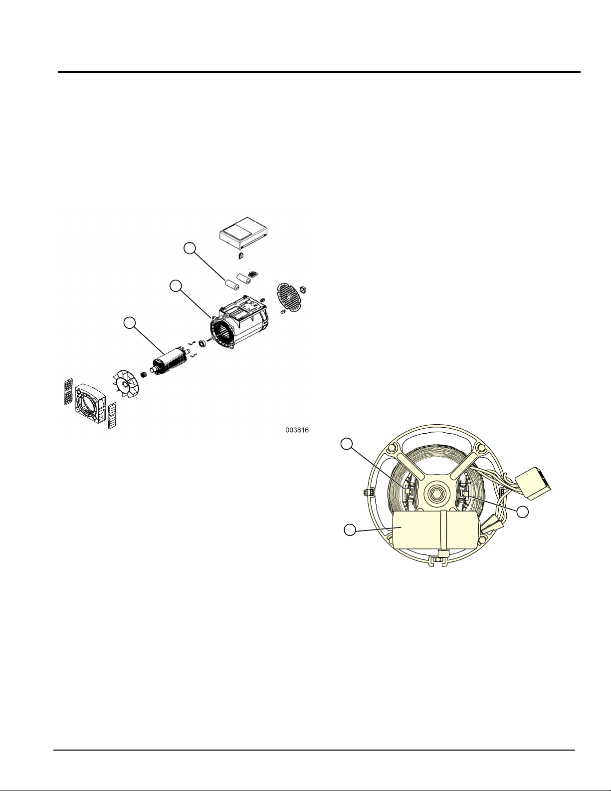
Rotor Assembly ........................................................1
Stator Assembly .......................................................1
Circuit Breakers .......................................................2
Operation .................................................................2
Troubleshooting Flowcharts .....................................3
If Problem Involves AC Output ..........................3
Problem 1 – Generator Produces Zero
Voltage or Residual Voltage ..............................3
Problem 2 – Voltage & Frequency Are
Both High or Low ...............................................4
Problem 3 – Excessive Voltage/Frequency
Droop When Load is Applied ............................4
Problem 4 – Generator Produces High
Voltage at No-Load ...........................................4
AC Diagnostic Tests ................................................5
Test 1 – Check No-Load Voltage and Frequency ....5
Test 2 – Check Main Circuit Breaker .......................5
Test 3 – Check Continuity of Receptacle Panel .......5
Test 5 – Field Flash Alternator .................................6
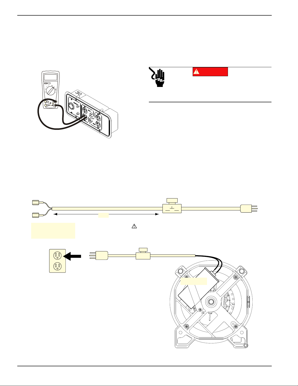
Test 6 – Check Capacitor ........................................7
Test 7 – Test Brushless Excitation Winding .............7
Test 8 – Test Brushless Stator Windings .................8
Test 10 – Check Load Voltage and Frequency ........8
Test 11 – Check Load Watts and Amperage ...........8
Section 2 Direct Excitation (Brush Type) .................. 11
Introduction ............................................................11
Stator Assembly .....................................................11
Brush Holder and Brushes .....................................11
Voltage Regulator ..................................................11
Operation ...............................................................12
Troubleshooting Flowcharts ...................................13
If Problem Involves AC Output (Brush Type) ..13
Problem 5 – Generator Produces Zero
Voltage or Residual Voltage ............................13
Problem 6 – Voltage & Frequency Are
Both High or Low .............................................13
Problem 7 – Excessive Voltage/Frequency
Droop When Load is Applied ..........................14
Problem 8 – Generator Produces High
Voltage at No-Load .........................................14
AC Diagnostic Tests ..............................................15
Test 1 – Check No-Load Voltage and Frequency ..15
Test 2 – Check Main Circuit Breaker .....................15
Test 3 – Check Continuity of Receptacle Panel ....15
Test 4 – Fixed Excitation Test/Rotor
Amp Draw Test ......................................16
Test Brushed Stator Windings ...............................18
Test 10 – Check Load Voltage and Frequency .....18
Test 11 – Check Load Watts and Amperage .........18
Test 12 – Adjust Voltage Regulator .......................19
Section 3 Engine Diagnostic Tests ........................... 21
Introduction ............................................................21
Problem 9 – Recoil Cord Will Not Pull ............21
Problem 10 – Engine Starts Hard and Runs
Rough .............................................................21
Problem 11 – Engine Turns Over But Will Not
Start ................................................................22
Problem 12 – Engine “Hunts” / Erratic Idle .....23
Problem 13 – Engine Will Not Crank ..............23
Problem 14 – Recoil Cord Will Not Pull
(If So Equipped) ..............................................23
Problem 15 – Engine Cranks But
Will Not Start ...................................................24
Problem 16 – Engine Starts Hard
and Runs Rough .............................................25
Problem 17 – Engine Starts Then
Shuts Down .....................................................25
Problem 18 – Battery Will Not Charge ............26
Problem 19 – Engine “Hunts” / Erratic Idle .....26
Problem 20 – Unit Will Not Idle .......................27
Problem 21 – Unit RPM Will Not Increase
From Idle .........................................................27
Problem 22 – No Display from Wattage/
Runtime Meter ................................................28
Problem 23 – Wattage/Runtime Meter
Display is Flashing Erroneous Data ................28
Introduction ............................................................29
Test 14 – Check Fuse ............................................29
Test 15 – Check Battery & Cables .........................29
Test 16 – Check Voltage at Starter
Contactor (SC) .......................................29
Test 17 – Check Start-Run-Stop Switch ................29
Test 18 – Test OFF-ON Switch .............................30
Test 19 – Check Starter Motor ...............................30
Test 20 – Check Ignition Spark ..............................31
Test 21 – Check Spark Plug(s) ..............................31

Diagnostic Repair Manual iv
Table of Contents
Test 22 – Check Carburetion .................................32
Test 23 – Choke Test .............................................32
Test 24 – Check Valve Adjustment ........................32
Test 25 – Check Engine / Cylinder Leak Down
Test / Compression Test ........................33
Test 26 – Check Ignition Coil .................................34
Test 27 – Check Flywheel ......................................35
Test 28 – Remove Shutdown Wire ........................35
Test 30 – Check / Adjust Governor (Mechanical) ..35
Test 31 – Check Oil Pressure Switch
(if equipped) ...........................................36
Test 32 – Check Oil Level Switch (if equipped) .....36
Test 33 – Test Recoil Function ..............................37
Test 34 – Test Engine Function .............................37
Test 35 – Test Battery Charger ..............................37
Test 36 – Test Idle control .....................................37
Section 4 Major Disassembly.................................... 39
Section 5 Electrical Data ........................................... 43

Diagnostic Repair Manual 1
Section 1 Capacitive Discharge (Brushless)
Introduction
See Figure 1-1. A typical brushless type portable
generator needs 4 major components to function: a prime
mover, rotor, stator, and capacitor.
As the engine begins to rotate, residual/permanent
magnetism from the rotor creates magnetic lines of flux.
The lines begin to cut across the excitation winding and
induce a small voltage into the winding. The voltage
causes the capacitor to charge.
Figure 1-1. AC Generator Exploded View
The capacitor on the excitation winding takes the place of
a voltage regulator. It will charge until AC peaks, then as
AC starts to fade it will discharge causing a voltage to be
induced into the rotor.
Two diodes in the rotor convert AC voltage to DC. There
is a diode in one pole that is orientated in one direction,
and a diode in the opposite pole orientated in the
opposite direction. This produces a North and South
poled rotor.
In one rotation of the rotor, the capacitor will charge and
discharge twice, inducing AC voltage into the rotor.
A capacitor discharge generator will produce a lower
voltage until load is applied. Once load is applied, the
output voltage will increase due to induction into the
excitation winding and capacitor.
As load is applied, current in the main AC windings
increases. This increase in current is also induced into
the excitation winding (much like a transformer
functions). The increased current into the excitation
winding causes voltage to increase which also increases
the charge/discharge value of the capacitor. This creates
a stronger magnetic field in the rotor and higher AC
output.
NOTE: Voltage will only increase from no load to full load
and will stop increasing at that point.
Rotor Assembly
The 2-pole rotor must be operated at 3600 rpm to supply
a 60 Hertz AC frequency. The term “2-pole” means the
rotor has a single north magnetic pole and a single south
magnetic pole. It spins freely inside the stator can and is
excited by the charging and discharging of the capacitor.
The rotor has two diodes that rectify voltage induced from
the excitation winding to DC voltage. Each winding/pole
will have a diode orientated to create current flow in one
direction, and the other winding/pole will have a diode
orientated to create current flow in the opposite direction.
This creates a North and South pole.
A rotor bearing is pressed onto the end of the rotor shaft.
The tapered rotor shaft is mounted to a tapered
crankshaft and is held in place with a single through bolt.
NOTE: Some rotors have a magnet placed inside the
laminations to help excite the rotor after it has been left
idle for a long period of time.
Figure 1-2. Rotor and Diodes
Stator Assembly
The stator has three windings wound separately inside
the can. Two are power windings located on Black Wires
(Hot) and White Wires (Neutral). The third winding is the
excitation winding and is on the Red Wires.
Some stator assemblies may be configured differently.
Always use the appropriate schematic and wiring
diagram for unit.
B
A
A. Rotor
B. Stator
C. Capacitor
A
B
C
003993
A. Diode
B. Capacitor
A
B
A

Section 1 Capacitive Discharge (Brushless)
2Diagnostic Repair Manual
Circuit Breakers
See Figure 1-3. Each individual circuit on the generator
is protected by a circuit breaker to prevent overload.
Figure 1-3. Generator Operating Diagram
Operation
Startup
When the engine is started, residual/permanent
magnetism from the rotor induces a voltage into (a) the
stator AC power windings, and (b) the stator excitation
windings. In an “On-speed” (engine cranking) condition,
residual/permanent magnetism is capable of creating
approximately one to three Volts AC.
On-Speed Operation
As the engine accelerates, the voltage that is induced
into the stator windings increases rapidly, due to the
increasing speed at which the rotor operates.
Field Excitation:
An AC voltage is induced into the stator excitation
windings. The excitation winding circuit is completed to
the capacitor where the capacitor is charged until the AC
voltage peaks and then discharges as the AC voltage
starts to decay. The charging and discharging causes a
voltage to be induced back into the rotor which will
produce voltage. The greater the current flow through the
rotor windings, the more concentrated the lines of flux
around the rotor become. The more concentrated the
lines of flux around the rotor that cut across the stationary
stator windings, the greater the voltage that is induced
into the stator windings. Initially, the AC power winding
voltage is low, but as the capacitor is charged and
discharged this relationship between the rotor and the
capacitor is what will regulate voltage at a desired level.
AC Power Winding Output
A maintained voltage is induced into the stator AC power
windings. When electrical loads are connected across
the AC power windings to complete the circuit, current
can flow in the circuit.
NOTE: The voltage of a brushless capacitive discharge
generator will start low and increase as load is applied.
CAPACITOR
003817
STATOR
EXCITATION
WINDING
STATOR
POWER
WINDING
STATOR
POWER
WINDING
MAGNETIC
FIELD
MAGNETIC
FIELD
MLB = MAIN LINE
CIRCUIT BREAKER
ROTOR
TO LOAD
MLB
ENGINE -
DIRECT
DRIVE
120 VAC 120 VAC
240 VAC

Section 1 Capacitive Discharge (Brushless)
Diagnostic Repair Manual 3
Troubleshooting Flowcharts
Introduction
Use the Flow Charts in conjunction with the AC Diagnostic Tests . Test numbers used in the flow charts correspond to
the numbered tests in the AC Diagnostic Tests . The first step in using the flow charts is to identify the correct problem
on the following pages. For best results, perform all tests in the exact sequence shown in the flow charts.
If Problem Involves AC Output
Problem 1 – Generator Produces Zero Voltage or Residual Voltage
GO TO PROBLEM 2 GO TO PROBLEM 1GO TO PROBLEM 4 GO TO PROBLEM 3
VOLTAGE &
FREQUENCY BOTH
HIGH OR LOW
FREQUENCY GOOD
VOLTAGE HIGH
ZERO VOLTAGE
ZERO FREQUENCY
FREQUENCY GOOD,
LOW OR RESIDUAL
VOLTAGE
TEST 1 - CHECK
NO LOAD VOLTAGE
& FREQUENCY
NO LOAD VOLTAGE &
FREQUENCY GOOD -
VOLTAGE/FREQUENCY
FALLS OFF UNDER LOAD
VERIFY ROTOR IS SPINNING,
GO TO PROBLEM 1
BAD
BAD
GOOD
GOOD
TEST 2 – CHECK
MAIN CIRCUIT
BREAKER
RESET TO “ON”
OR REPLACE IF BAD REPLACE COMPONENT
AS NEEDED
STOP
TESTING
TEST 3 – CHECK
CONTINUITY OF
RECEPTACLE PANEL
RE-CHECK VOLTAGE
AT RECEPTACLE
PANEL
TEST 5 – FIELD
FLASH
ALTERNATOR
REPLACE
BAD
BAD
BAD
REPLACE
STATOR
REPLACE
ROTOR
ON
GOODGOODGOOD
TEST 6 –
CHECK
CAPACITOR
TEST 7 – TEST
BRUSHLESS
EXCITATION
WINDING
TEST 8 – TEST
BRUSHLESS
STATOR
WINDINGS

Section 1 Capacitive Discharge (Brushless)
4Diagnostic Repair Manual
Problem 2 – Voltage & Frequency Are Both High or Low
Problem 3 – Excessive Voltage/Frequency Droop When Load is Applied
Problem 4 – Generator Produces High Voltage at No-Load
TEST 30 – CHECK & ADJUST
ENGINE GOVERNOR
GO TO
PROBLEM 1
GO TO
PROBLEM 3
GO TO PROBLEM 1,
TEST 6 – CHECK
CAPACITOR
FREQUENCY GOOD, LOW OR
RESIDUAL VOLTAGE
FREQUENCY IS GOOD BUT
NO-LOAD VOLTAGE IS HIGH
NO-LOAD FREQUENCY & VOLTAGE GOOD BUT
THEY DROOP TO MUCH WHEN LOAD IS APPLIED
GO TO PROBLEM 23
REDUCE LOAD
END TEST
Problem 3 – Excessive Voltage/Frequency Droop When Load is Applied
TEST 10 – CHECK
LOAD VOLTAGE &
FREQUENCY
TEST 11 – CHECK
LOAD WATTS &
AMPERAGE
GOOD
GOOD
BAD
OVERLOADED
NOT OVERLOADED
TEST 30 – CHECK
& ADJUST
ENGINE
GOVERNOR
STOP
TESTS
REPLACE
TEST 1 – CHECK
NO-LOAD VOLTAGE
AND FREQUENCY
FREQUENCY AND
VOLTAGE O.K.
FREQUENCY O.K.,
BUT VOLTAGE HIGH
FREQUENCY
HIGH
BAD
GO TO “PROBLEM 1”,
TEST 7 – TEST BRUSHLESS
EXCITATION WINDING
FREQUENCY O.K., BUT VOLTAGE IS STILL HIGH
TEST 6 –
CHECK
CAPACITOR
TEST 30 – CHECK & ADJUST
ENGINE GOVERNOR

Section 1 Capacitive Discharge (Brushless)
Diagnostic Repair Manual 5
AC Diagnostic Tests
Introduction
The Diagnostic Tests in this section may be performed in
conjunction with the Troubleshooting Flowcharts . Test
numbers in this chapter correspond to numbered tests in
the flow charts.
NOTE: Test procedures in this manual are not
necessarily the only methods for diagnosing the condition
of components and circuits. All possible methods that
might be used for system diagnosis have not been
evaluated. If any diagnostic method is used other than
the method presented in this manual, the technician must
be sure that neither his personal safety, nor the product's
safety, will be endangered by the procedure or method
that has been selected.
Test 1 – Check No-Load Voltage and
Frequency
Procedure
1. Disconnect or turn OFF all electrical loads
connected to the generator.
2. Set digital multimeter (DMM) to measure AC
voltage.
3. Reset all circuit breakers to ON.
4. Start engine and let stabilize and warm up.
5. See Figure 1-4. Place meter test leads into an
outlet.
Figure 1-4. DMM Test Leads Connected to a 240 VAC
Receptacle
6. Read AC voltage.
7. Connect an AC frequency meter as described in
Step 5.
8. Read AC frequency.
Results
Refer to flow chart.
Test 2 – Check Main Circuit Breaker
Procedure
The generator has circuit breakers located on the control
panel. If outlets are not receiving power, make sure
breakers are set to ON or “Closed”.
If a breaker is suspected to have failed, test as follows:
1. Set DMM to measure resistance.
2. With generator shut down, disconnect all wires
from suspected circuit breaker terminals to prevent
interaction.
3. See Figure 1-5. With the generator shut down,
connect one meter test lead to one terminal of the
breaker and the other meter test lead to the other
terminal.
4. Set breaker to ON or “Closed”. The meter should
read CONTINUITY.
5. Set breaker to OFF or “Open”. The meter should
indicate INFINITY.
Figure 1-5. 20/30 Amp Breaker Test Points
Results
1. If circuit breaker tests good, refer to flow chart.
2. If breaker tests bad, replace.
Test 3 – Check Continuity of
Receptacle Panel
General Theory
Continuity of the receptacle panel is important as it
recognizes the receptacle has continuity through the
wiring and is physically connected to the stator. Most
stator winding values are between 0.01 and 0.02 Ohms
of resistance. If a higher than normal ohm reading is
shown, a poor connection could be the problem
preventing that receptacle from receiving power.
Procedure
1. Set DMM to measure Resistance.
2. See Figure 1-6. Connect DMM to each receptacle
on unit.
No Load Voltage No Load Frequency
223.2 – 256.8 VAC 62.5 – 62.0 Hz
240
00.01 C.B.
20/30A

Section 1 Capacitive Discharge (Brushless)
6Diagnostic Repair Manual
NOTE: Only one outlet on each receptacle needs to be
tested.
Results
1. If any other reading than continuity was measured,
further troubleshooting needs to be done to
determine if it is the receptacle or the wiring.
2. If receptacles test good, refer to flow chart.
Figure 1-6. Checking Continuity of Receptacles
Test 5 – Field Flash Alternator
General Theory
The alternator utilizes residual magnetism within the
windings to charge the capacitor. If the generator has not
been started for a long period of time, the residual
magnetism could be lost within the rotor. Field flashing
the rotor while connected in parallel with the capacitor will
force a charge of electricity through the excitation
winding. The voltage that is induced into the rotor will
charge the rotor with enough residual magnetism it will
charge the capacitor during normal operation.
Procedure
1. Construct an energizing cord similar to Figure 1-7
and connect as shown in Figure 1-8.
2. Set START-RUN-STOP switch to OFF.
IMPORTANT NOTE: Do NOT energize the capacitor for
more than 1 second at a time.
3. Momentarily turn on energizing cord (one second).
4. Disconnect energizing cord from capacitor.
Figure 1-7. Construction of Energizing Cord
Figure 1-8. Connecting Energizing Cord
0.01 Ohms
(000343)
Electrocution. Potentially lethal voltages are present
in this equipment. Render the equipment safe before
attempting repairs or maintenance. Failure to do so
will result in death or serious injury.
DANGER
12 AWG12 AWG
MOMENTARY PUSHBUTTON ON/OFF SWITCH
SINGLE POLE SWITCH ON LIVE SIDE
DO NOT SUBSTITUTE ANY OTHER DEVICE
4 ft.
CRIMP ON STANDARD
FEMALE BLADE
CONNECTORS
STANDARD
MALE PLUG
003923
CAPACITOR
003924
DEPRESS SWITCH FOR
ONE SECOND
PLUG ENERGIZING CORD
INTO AC OUTLET
CAPICITOR REMAINS CONNECTED
TO GENERATOR
Danger: The capacitor may need to be
discharged before testing. A capacitor can
be discharged by crossing the terminals
with a metal insulated screw driver.
Danger: Use proper protective equipment
when dealing with a capacitor that has
exploded.

Section 1 Capacitive Discharge (Brushless)
Diagnostic Repair Manual 7
5. If the field flash was successful, the generator
should produce approximately 240 VAC at the
main circuit breaker of the generator when the
START-RUN-STOP is set to START.
IMPORTANT NOTE: Do not field flash alternator more
than two times in sequence. If the unit has not produced
power after two attempts, other issues exist and need to
be addressed.
Results
1. Refer to flow chart.
Test 6 – Check Capacitor
General Theory
The brushless rotor system relies on the charging and
discharging of a capacitor to induce voltage into the rotor,
and also maintains voltage once 240 VAC is achieved. If
the capacitor fails, only residual magnetism of the rotor
will be measured at the main breaker.
NOTE: The voltage of a brushless capacitive discharge
generator will start low and increase as load is applied.
IMPORTANT NOTE: The capacitor may need to be
discharged before testing. A capacitor can be discharged
by crossing the terminals with a metal insulated screw
driver.
IMPORTANT NOTE: Use proper protective equipment
when dealing with a capacitor that has exploded.
Procedure
1.
Consult the owner’s manual of the meter being used
for directions on measuring capacitance.
Figure 1-9
shows a typical meter and how to check capacitance.
2. Connect meter leads directly across the terminals
of capacitor. The rated µf (micro farad) of the
capacitor is marked on the side of the canister.
3. The meter should display the correct µf reading ±
5µf. If anything other than the indicated rating is
displayed, replace the capacitor.
Results
1. Refer to flow chart.
2. Visually observe the capacitor.
a. A capacitor that has gone bad has a tendency
to explode. Use caution when dealing with an
exploded capacitor, the gel from inside a
capacitor can cause skin irritation.
b. A capacitor is defective if terminal connections
are loose on the canister.
c. A capacitor is defective if it wobbles while
sitting on a flat surface.
d. If any of these traits are observed, replace
capacitor.
Figure 1-9. Capacitor Test Points (Alternator
Configuration “A”)
Test 7 – Test Brushless Excitation
Winding
General Theory
An excitation winding is used to charge a capacitor. It
discharges and charges, releasing a voltage that is
induced into the rotor. If the excitation winding fails, only
residual magnetism of the rotor will be measured at the
main breaker.
NOTE:
The resistance of stator windings is very low. Some
meters will not read such a low resistance, and will simply
indicate CONTINUITY. Recommended is a high quality,
digital type meter capable of reading very low resistances.
IMPORTANT NOTE:
The capacitor may need to be
discharged before testing. A capacitor can be discharged by
crossing the terminals with a metal insulated screw driver.
Procedure
1. Disconnect Red Wires from capacitor.
2. Set DMM to measure resistance.
3. Connect meter leads to excitation winding leads.
a. Reading should be approximately to the values
found in the specifications.
4. Connect a meter lead to one excitation winding
lead and connect the other meter lead to a clean
frame ground, INFINITY should be measured.
Repeat this step with the other excitation lead.
5. Isolate the stator wire so the stator is disconnected
from the receptacle panel and the capacitor.
NOTE: Isolate all main stator leads before proceeding.
003995
59.0
μf

Section 1 Capacitive Discharge (Brushless)
8Diagnostic Repair Manual
6. Connect one meter lead to an excitation winding
and connect the other meter lead to a power
winding. INFINITY should be measured.
7. Repeat Step 6 using an excitation winding and
another power winding. INFINITY should be
measured.
Results
1. Stator winding resistance values is a test of
winding continuity and resistance. If a very high
resistance or INFINITY is indicated, the winding is
open or partially open.
2. Test for a “grounded” condition: Any resistance
reading indicates the winding is grounded.
3. Test for a “shorted” condition: Any resistance
reading indicates the winding is shorted.
4. If stator tests good and wire continuity tests good,
refer to flow chart.
Test 8 – Test Brushless Stator
Windings
General Theory
The brushless stator has three internal windings, two
main power windings and an excitation winding. This test
will ensure there are no shorts between the power
windings or shorts to ground.
A DMM can be used to test the stator windings for the
following faults:
•An open circuit condition
•A “short-to-ground” condition
•A short circuit between windings
NOTE: The resistance of stator windings is very low.
Some meters will not read such a low resistance, and will
simply indicate CONTINUITY. Recommended is a high
quality, digital type meter capable of reading very low
resistances.
Procedure
1. Disconnect all power windings from the receptacle
panel so the stator is isolated.
2. Make sure all the disconnected leads are isolated
from each other, and are not touching the frame
during the test.
3. Set DMM to measure resistance.
4. Connect one test lead to one stator power winding
lead. Connect the other test lead to the other stator
power winding lead of the same winding. Stator
resistance should be as referenced in the
specifications.
5. Repeat step 4 with the other power windings.
Stator resistance should be as referenced in the
specifications.
Test windings for a short to ground:
1. Make sure all leads are isolated from each other
and are not touching the frame.
2. Connect one test lead to a clean frame ground.
Connect the other test lead to a stator lead.
a. The meter should read INFINITY.
b. Any reading other than INFINITY indicates a
“short to ground” condition.
3. Repeat Step 2 using the other stator lead.
Test for a short circuit between windings:
1. Make sure all leads are isolated from each other
and are not touching the frame.
2. Connect one test lead to a stator lead. Connect the
other test lead to the other stator lead.
a. The meter should read INFINITY.
b. Any reading other that INFINITY indicates a
short between windings.
Test 10 – Check Load Voltage and
Frequency
Procedure
Perform this test the same as Test 1 but apply a load to
the generator equal to its rated capacity. With load
applied check voltage and frequency.
Frequency should not drop below about 59 Hertz with
load applied.
Voltage should not drop below about 220 VAC nor rise
above 265 VAC with load applied.
Results
1. If voltage and/or frequency drop excessively when
load is applied, refer to flow chart.
2. If load voltage and frequency are within limits, end
tests.
Test 11 – Check Load Watts and
Amperage
Procedure
Add up the wattages or amperages of all loads powered
by the generator at one time. If desired, a clamp-on
ammeter may be used to measure current flow.
See the Wattage Reference Guide to determine
generator limits.
NOTE: All figures are approximate. See data label on
appliance for wattage requirements.
Results
1. If unit is overloaded, reduce load.

Section 1 Capacitive Discharge (Brushless)
Diagnostic Repair Manual 9
2. If load is within limits but frequency and voltage still
drop excessively, refer to flow chart.
Overloading a generator in excess of its rated wattage
capacity can result in damage to the generator and to
connected electrical devices. Observe the following to
prevent overloading unit:
•Add up total wattage of all electrical devices to be
connected at one time. This total should NOT be
greater than the wattage capacity of the generator.
•The rated wattage of lights can be taken from light
bulbs. The rated wattage of tools, appliances and
motors can be found on a data label or decal
affixed to the device.
•If the appliance, tool or motor does not give
wattage, multiply volts times ampere rating to
determine watts (volts x amps = watts).
•Some electric motors, such as induction types,
require about three times more watts of power for
starting than for running. This surge of power lasts
only a few seconds when starting such motors.
Make sure to allow for high starting wattage when
selecting electrical devices to connect to the generator:
1. Figure watts needed to start the largest motor.
2. Add to that figure the running watts of all other
connected loads.
Wattage Reference Guide
Device Running Watts Device Running Watts
*Air Conditioner (12,000 Btu) 1700 Hand Drill 250 to 1100
*Air Conditioner (24,000 Btu) 3800 Hedge Trimmer 450
*Air Conditioner (40,000 Btu) 6000 Impact Wrench 500
Battery Charger (20 Amp) 500 Iron 1200
Belt Sander (3") 1000 *Jet Pump 800
Chain Saw 1200 Lawn Mower 1200
Circular Saw (6-1/2”) 800 to 1000 Light Bulb 100
*Clothes Dryer (Electric) 5750 Microwave Oven 700 to 1000
*Clothes Dryer (Gas) 700 *Milk Cooler 1100
*Clothes Washer 1150 Oil Burner on Furnace 300
Coffee Maker 1750 Oil Fired Space Heater (140,000 Btu) 400
*Compressor (1 HP) 2000 Oil Fired Space Heater (85,000 Btu) 225
*Compressor (3/4 HP) 1800 Oil Fired Space Heater (30,000 Btu) 150
*Compressor (1/2 HP) 1400 *Paint Sprayer, Airless (1/3 HP) 600
Curling Iron 700 Paint Sprayer, Airless (hand held) 150
*Dehumidifier 650 Radio 50 to 200
Disc Sander (9") 1200 *Refrigerator 700
Edge Trimmer 500 Slow Cooker 200
Electric Blanket 400 *Submersible Pump (1-1/2 HP) 2800
Electric Nail Gun 1200 *Submersible Pump (1 HP) 2000
Electric Range (per element) 1500 *Submersible Pump (1/2 HP) 1500
Electric Skillet 1250 *Sump Pump 800 to 1050
*Freezer 700 *Table Saw (10") 1750 to 2000
*Furnace Fan (3/5 HP) 875 Television 200 to 500
*Garage Door Opener 500 to 750 Toaster 1000 to 1650
Hair Dryer 1200 Weed Trimmer 500
* Allow 3 times the listed watts for starting these devices.

Section 1 Capacitive Discharge (Brushless)
10 Diagnostic Repair Manual
Rotor And Stator Resistance
Series Model Generator
Type Engine Type Alternator Rotor Ohms Power /
Sensing Ohms Exciter Ohms Capacitor µF
DXGN4500 PD422MHI005 CD/A GX270 S16W-105 3.510 0.570 3.129 20.00
DXGN6000 PD532MHI005 CD/A GX340 S16W-130 3.950 0.360 2.446 25.00
DXGN7200 PD612MHB005 CD/A GX390 S16W-150 4.380 0.326 2.012 31.50
DXGN14000 PD123MHB007 CD/A GX630 S20SF-160 6.570 0.124 0.600 35.00

Diagnostic Repair Manual 11
Section 2 Direct Excitation (Brush Type)
Introduction
See Figure 1-1. A typical brush type portable generator
needs 4 major components to function: prime mover,
rotor, stator, and voltage regulator.
As the engine begins to rotate, residual magnetism from
the rotor creates magnetic lines of flux. The lines begin to
cut across the excitation winding and induce a small
voltage into the voltage regulator. The excitation voltage
will power the voltage regulator and the voltage regulator
will start to sense AC voltage from Wires S15 and S16.
The lower voltage from the sensing wires will cause DC
excitation to the rotor to be driven up until AC output is at
desired level of 240 VAC. Once the generator has
reached 240 VAC it will maintain the DC voltage,
regulating the alternator when loads are applied and
removed.
Figure 1-1. AC Generator Exploded View
Stator Assembly
The stator has three windings wound separately inside
the can. Two are the power windings and are located on
Wire 44 (Hot) and Wire 33 (Neutral); the other winding is
located on Wire 11 (Hot) and Wire 22 (neutral). The third
winding is called excitation winding and is located on
Wire 2 and Wire 6.
Some generators have color coded wires. Always use
the appropriate schematic and wiring diagram for unit.
Brush Holder and Brushes
The brush holder has a positive (+) and a negative (-)
brush, and is retained to the rear bearing carrier by
means of two Taptite screws. Wire 4 connects to the
positive (+) brush and Wire 0 to the negative (-) brush.
Rectified and regulated excitation current is delivered to
the rotor windings via Wire 4, and the positive (+) brush
and slip ring. The excitation current passes through the
windings to the negative (-) slip ring and brush on Wire 0.
This current flow creates a magnetic field around the rotor
having a flux concentration that is proportional to the
amount of current flow.
Figure 1-2.
Voltage Regulator
See Figure 1-3. Unregulated AC output from the stator
excitation winding is delivered to the regulator DPE via
blue excitation winding wires. The voltage regulator
rectifies that current and, based on stator AC power
winding sensing, regulates it. The rectified and regulated
excitation current is then delivered to the rotor windings
from the positive (+) and negative (-) regulator terminals,
via red field positive and white field negative wires. Stator
AC power winding “sensing” is delivered to the regulator
via the green and white wires.
Figure 1-3.
A. Rotor
B. Stator
C. Brushes
D. Voltage Regulator
A
B
C
D
A.
B.
A
B

Section 2 Direct Excitation (Brush Type)
12 Diagnostic Repair Manual
Operation
Startup
When the engine is started, residual magnetism from the
rotor induces a voltage into (a) the stator AC power
windings, (b) the stator excitation windings. In an “on-
speed” (engine cranking) condition, residual magnetism is
capable of creating approximately one to three volts AC.
On-Speed Operation
As the engine accelerates, the voltage that is induced
into the stator windings increases rapidly, due to the
increasing speed at which the rotor operates.
Field Excitation
An AC voltage is induced into the stator excitation
windings. The
excitation
winding circuit is completed to
the voltage regulator, via the blue wires. Unregulated
alternating current can flow from the winding to the
regulator. The voltage regulator senses AC power
winding output voltage and frequency via the stator green
and white wires.
The regulator changes the AC from the excitation
winding to DC. In addition, based on the sensing signals,
it regulates the flow of direct current to the rotor. The
rectified and regulated current flow from the regulator is
delivered to the rotor windings, via red field positive wire,
and the positive brush and slip ring. This excitation
current flows through the rotor windings and through the
negative (-) slip ring and brush on white field negative
wire.
The greater the current flow through the rotor windings,
the more concentrated the lines of flux around the rotor
become. The more concentrated the lines of flux around
the rotor that cut across the stationary stator windings,
the greater the voltage that is induced into the stator
windings.
Initially, the AC power winding voltage sensed by the
regulator is low. The regulator reacts by increasing the
flow of excitation current to the rotor until voltage
increases to a desired level. The regulator then maintains
the desired voltage. For example, if voltage exceeds the
desired level, the regulator will decrease the flow of
excitation current. Conversely, if voltage drops below the
desired level, the regulator responds by increasing the
flow of excitation current.
AC Power Winding Output
A regulated voltage is induced into the stator AC power
windings. When electrical loads are connected across
the AC power windings to complete the circuit, current
can flow in the circuit.
Figure 1-4. Generator Operating Diagram
AUTOMATIC
VOLTAGE
REGULATOR
+-
STATOR
EXCITATION
WINDING
STATOR
POWER
WINDING
STATOR
POWER
WINDING
MAGNETIC
FIELD
MAGNETIC
FIELD
SENSING
MLB = MAIN LINE
CIRCUIT BREAKER
ROTOR
TO LOAD
MLB
ENGINE -
DIRECT
DRIVE
120 VAC 120 VAC
240 VAC

Section 2 Direct Excitation (Brush Type)
Diagnostic Repair Manual 13
Troubleshooting Flowcharts
Introduction
Use the Flow Charts in conjunction with the AC Diagnostic Tests . Test numbers used in the flow charts correspond to
the numbered tests in the AC Diagnostic Tests . The first step in using the flow charts is to identify the correct problem
on the following pages. For best results, perform all tests in the exact sequence shown in the flow charts.
If Problem Involves AC Output (Brush Type)
Problem 5 – Generator Produces Zero Voltage or Residual Voltage
Problem 6 – Voltage & Frequency Are Both High or Low
GO TO PROBLEM 6 GO TO PROBLEM 5GO TO PROBLEM 8 GO TO PROBLEM 7
VOLTAGE &
FREQUENCY BOTH
HIGH OR LOW
FREQUENCY GOOD
VOLTAGE HIGH
ZERO VOLTAGE
ZERO FREQUENCY
FREQUENCY GOOD,
LOW OR RESIDUAL
VOLTAGE
TEST 1 - CHECK
NO LOAD VOLTAGE
& FREQUENCY
NO LOAD VOLTAGE &
FREQUENCY GOOD -
VOLTAGE/FREQUENCY
FALLS OFF UNDER LOAD
VERIFY ROTOR IS SPINNING,
GO TO PROBLEM 5
BAD
BAD
GOOD
TEST 2 – CHECK
MAIN CIRCUIT
BREAKER
RESET TO “ON”
OR REPLACE IF BAD REPLACE COMPONENT
AS NEEDED
REPLACE COMPONENT
AS NEEDED
TEST 3 – CHECK
CONTINUITY OF
RECEPTACLE PANEL
REPLACE
ALTERNATOR
REPLACE AUTOMATIC
VOLTAGE REGULATOR
TEST 4 – FIXED
EXCITATION
TEST/ROTOR AMP
DRAW TEST
ON
GOOD
STOP TESTING
GOOD
BAD
RE-CHECK VOLTAGE
AT RECEPTACLE
PANEL

Section 2 Direct Excitation (Brush Type)
14 Diagnostic Repair Manual
Problem 7 – Excessive Voltage/Frequency Droop When Load is Applied
Problem 8 – Generator Produces High Voltage at No-Load
TEST 29 – CHECK & ADJUST
ENGINE GOVERNOR
GO TO
PROBLEM 5
GO TO
PROBLEM 7
GO TO PROBLEM 5,
TEST 12 – ADJUST
VOLTAGE
REGULATOR
FREQUENCY
GOOD, LOW OR
RESIDUAL VOLTAGE
FREQUENCY IS GOOD
BUT NO-LOAD
VOLTAGE IS HIGH
NO-LOAD FREQUENCY &
VOLTAGE GOOD BUT
THEY DROOP TOO MUCH
WHEN LOAD IS APPLIED
GO TO PROBLEM 23
REDUCE LOAD
END TEST
TEST 10 – CHECK
LOAD VOLTAGE &
FREQUENCY
TEST 11 – CHECK
LOAD WATTS &
AMPERAGE
GOOD
GOOD
BAD
OVERLOADED
NOT OVERLOADED
TEST 29 – CHECK
& ADJUST
ENGINE
GOVERNOR
REPLACE
ALTERNATOR BAD
STOP
TESTS
FREQUENCY AND
VOLTAGE O.K.
FREQUENCY O.K.,
BUT VOLTAGE IS
STILL HIGH
TEST 29 – CHECK & ADJUST
ENGINE GOVERNOR
TEST 1 – CHECK
NO-LOAD VOLTAGE
AND FREQUENCY
TEST 12 – ADJUST
VOLTAGE
REGULATOR
FREQUENCY O.K.,
BUT VOLTAGE HIGH
FREQUENCY
HIGH
REPLACE AUTOMATIC
VOLTAGE REGULATOR GOOD
RE-CHECK VOLTAGE
AT RECEPTACLE
PANEL

Section 2 Direct Excitation (Brush Type)
Diagnostic Repair Manual 15
AC Diagnostic Tests
Introduction
The Diagnostic Tests in this chapter may be performed in
conjunction with the Troubleshooting Flow Charts. Test
numbers in this chapter correspond to numbered tests in
the flow charts.
NOTE: Test procedures in this manual are not
necessarily the only methods for diagnosing the condition
of components and circuits. All possible methods that
might be used for system diagnosis have not been
evaluated. If any diagnostic method is used other than
the method presented in this manual, the technician must
be sure that neither his personal safety, nor the product's
safety, will be endangered by the procedure or method
that has been selected.
NOTE: For graphics of different configurations of stators
and the wire numbers associated with different
components, see appropriate wiring diagrams and
schematics for the generator.
Test 1 – Check No-Load Voltage and
Frequency
Procedure
1. Disconnect or turn OFF all electrical loads
connected to the generator.
2. Set digital multimeter (DMM) to measure AC
voltage.
3. Reset all circuit breakers to ON.
4. Start engine and let stabilize and warm up.
5. See Figure 1-5. Place meter test leads into an
outlet.
Figure 1-5. DMM Test Leads Connected to a 240 VAC
Receptacle
6. Read AC voltage.
7. Connect an AC frequency meter as described in
Step 5.
8. Read AC frequency.
Results
Refer to flow chart.
Test 2 – Check Main Circuit Breaker
Procedure
The generator has circuit breakers located on the control
panel. If outlets are not receiving power, make sure
breakers are set to ON or “Closed”.
If a breaker is suspected to have failed, test as follows:
1. Set DMM to measure resistance.
2. With generator shut down, disconnect all wires
from suspected circuit breaker terminals to prevent
interaction.
3. See Figure 1-6. With the generator shut down,
connect one meter test lead to one terminal of the
breaker and the other meter test lead to the other
terminal.
4. Set breaker to ON or “Closed”. The meter should
read CONTINUITY.
5. Set breaker to OFF or “Open”. The meter should
indicate INFINITY.
Figure 1-6. 20/30 Amp Breaker Test Points
Results
1. If circuit breaker tests good, refer to flow chart.
2. If breaker tests bad, replace.
Test 3 – Check Continuity of
Receptacle Panel
General Theory
Continuity of the receptacle panel is important as it
recognizes the receptacle has continuity through the
wiring and is physically connected to the stator. Most
stator winding values are between 0.01 and 0.02 Ohms
of resistance. If a higher than normal ohm reading is
shown, a poor connection could be the problem
preventing that receptacle from receiving power.
240
No Load Voltage No Load Frequency
223.2 – 256.8 VAC 62.5 – 62.0 Hz
00.01 C.B.
20/30A

Section 2 Direct Excitation (Brush Type)
16 Diagnostic Repair Manual
Procedure
1. Set DMM to measure Resistance.
2. See Figure 1-7. Connect DMM to each receptacle
on unit.
NOTE: Only one outlet on each receptacle needs to be
tested.
Results
1. If any other reading than continuity was measured,
further troubleshooting needs to be done to
determine if it is the receptacle or the wiring.
2. If receptacles test good, refer to flow chart.
Figure 1-7. Checking Continuity of Receptacles
Test 4 – Fixed Excitation Test/Rotor
Amp Draw Test
General Theory
Supplying a fixed DC current to the rotor will induce a
magnetic field in the rotor. With the generator running,
this should create a proportional voltage output from the
stator windings.
NOTE: A standard 12 Volt battery is needed for this
procedure.
NOTE: Always use the unit specific schematics and
wiring diagrams for brush orientation.
Procedure
1. Remove positive and negative wires connected to
the brush assembly.
2. Connect one jumper wire to where the positive
brush wire was connected to on the brush
assembly.
3. Connect another jumper wire to where the negative
brush wire was connected to on the brush
assembly.
NOTE: For safety, install an in-line fuse in the positive
jumper wire. Maximum fuse should be 2 amps.
4. Set DMM to measure AC Voltage.
5. See Figure 2-8. Connect meter test leads across
the 240 VAC receptacle so the leads read line-to-
line voltage.
6. Set RUN-STOP switch to RUN and start unit.
Figure 2-8. Jumper Wires Between Battery and Brush Assembly
0.01 Ohms
!62
6/,4
"!44%29
6!#
2%#%04!#,%
6!#
&53%
"253(!33%-",9
003973
This manual suits for next models
11
Table of contents
Other DeWalt Portable Generator manuals

DeWalt
DeWalt DXGNSeries User manual

DeWalt
DeWalt DXGNSeries User manual

DeWalt
DeWalt DXSTA151PS User manual

DeWalt
DeWalt DXGNR4000 User manual

DeWalt
DeWalt DXGNP30E User manual

DeWalt
DeWalt DXGNR 7000 User manual

DeWalt
DeWalt DG3000 User manual

DeWalt
DeWalt DXGNR 5700 User manual

DeWalt
DeWalt DG series User manual

DeWalt
DeWalt DXGNR 6500 User manual