DeWalt DW300 User manual

DW300
VS Orbital Jig Saw
INSTRUCTION MANUAL
Questions? See us on the World Wide Web at www.dewalt.com
FINAL PRINT SIZE: 5.5 x 8.5"


1
English
Definitions: Safety Guidelines
The definitions below describe the level of severity for each
signal word. Please read the manual and pay attention to these
symbols.
DANGER: Indicates an imminently hazardous situation which,
if not avoided, will result in death or serious injury.
WARNING: Indicates a potentially hazardous situation which,
if not avoided, could result in death or serious injury.
CAUTION: Indicates a potentially hazardous situation which, if
not avoided, may result in minor or moderate injury.
NOTICE: indicates a practice not related to personal injury
which, if not avoided, may result in property damage.
WARNING: To reduce the risk of injury, read the instruction
manual.
General Power Tool Safety Warnings
WARNING! Read all safety warnings and all instructions
Failure to follow the warnings and instructions may result in
electric shock, fire and/or serious injury.
SAVE ALL WARNINGS AND INSTRUCTIONS
FOR FUTURE REFERENCE
The term “power tool” in the warnings refers to your mains-operated
(corded) power tool or battery-operated (cordless) power tool.
1) WORK AREA SAFETY
a) Keep work area clean and well lit. Cluttered or dark areas
invite accidents.
b) Do not operate power tools in explosive atmospheres,
such as in the presence of flammable liquids, gases or
dust. Power tools create sparks which may ignite the dust or
fumes.
c) Keep children and bystanders away while operating a
power tool. Distractions can cause you to lose control.
2) ELECTRICAL SAFETY
a) Power tool plugs must match the outlet. Never modify
the plug in any way. Do not use any adapter plugs with
earthed (grounded) power tools. Unmodified plugs and
matching outlets will reduce risk of electric shock.
b) Avoid body contact with earthed or grounded surfaces
such as pipes, radiators, ranges and refrigerators. There
is an increased risk of electric shock if your body is earthed or
grounded.
c) Do not expose power tools to rain or wet conditions.
Water entering a power tool will increase the risk of electric
shock.
d) Do not abuse the cord. Never use the cord for carrying,
pulling or unplugging the power tool. Keep cord away
from heat, oil, sharp edges or moving parts. Damaged or
entangled cords increase the risk of electric shock.
e) When operating a power tool outdoors, use an extension
cord suitable for outdoor use. Use of a cord suitable for
outdoor use reduces the risk of electric shock.
f) If operating a power tool IN A DAmp location is
unavoidable, use a residual current device (RCD)
protected supply. Use of an RCD reduces the risk of electric
shock.
3) PERSONAL SAFETY
a) Stay alert, watch what you are doing and use common
sense when operating a power tool. Do not use a power
tool while you are tired or under the influence of drugs,
alcohol or medication. A moment of inattention while
operating power tools may result in serious personal injury.
b) Use personal protective equipment. Always wear eye
protection. Protective equipment such as dust mask, non-

2
English
skid safety shoes, hard hat, or hearing protection used for
appropriate conditions will reduce personal injuries.
c) Prevent unintentional starting. Ensure the switch is in
the off position before connecting to power source and/
or battery pack, picking up or carrying the tool. Carrying
power tools with your finger on the switch or energising power
tools that have the switch on invites accidents.
d) Remove any adjusting key or wrench before turning the
power tool on. A wrench or a key left attached to a rotating
part of the power tool may result in personal injury.
e) Do not overreach. Keep proper footing and balance at
all times. This enables better control of the power tool in
unexpected situations.
f) Dress properly. Do not wear loose clothing or jewellery.
Keep your hair, clothing and gloves away from moving
parts. Loose clothes, jewellery or long hair can be caught in
moving parts.
g) If devices are provided for the connection of dust
extraction and collection facilities, ensure these are
connected and properly used. Use of dust collection can
reduce dust-related hazards.
4) POWER TOOL USE AND CARE
a) Do not force the power tool. Use the correct power tool
for your application. The correct power tool will do the job
better and safer at the rate for which it was designed.
b) Do not use the power tool if the switch does not turn it
on and off. Any power tool that cannot be controlled with the
switch is dangerous and must be repaired.
c) Disconnect the plug from the power source and/or the
battery pack from the power tool before making any
adjustments, changing accessories, or storing power
tools. Such preventive safety measures reduce the risk of
starting the power tool accidentally.
d) Store idle power tools out of the reach of children and
do not allow persons unfamiliar with the power tool or
these instructions to operate the power tool. Power tools
are dangerous in the hands of untrained users.
e) Maintain power tools. Check for misalignment or binding
of moving parts, breakage of parts and any other
condition that may affect the power tool’s operation. If
damaged, have the power tool repaired before use. Many
accidents are caused by poorly maintained power tools.
f) Keep cutting tools sharp and clean. Properly maintained
cutting tools with sharp cutting edges are less likely to bind and
are easier to control.
g) Use the power tool, accessories and tool bits etc., in
accordance with these instructions taking into account
the working conditions and the work to be performed.
Use of the power tool for operations different from those
intended could result in a hazardous situation.
5) SERVICE
a) Have your power tool serviced by a qualified repair
person using only identical replacement parts. This will
ensure that the safety of the power tool is maintained.
SPECIFIC SAFETY RULES
Safety Warnings for Jig Saws
•Hold power tools by insulated gripping surfaces when
performing an operation where the cutting tool may
contact hidden wiring or its own cord. Contact with a “live”
wire will make exposed metal parts of the tool “live” and shock the
operator.
• Use clamps or another practical way to secure and support
the work piece to a stable platform. Holding the work by hand
or against your body leaves it unstable and may lead to loss of
control.

3
English
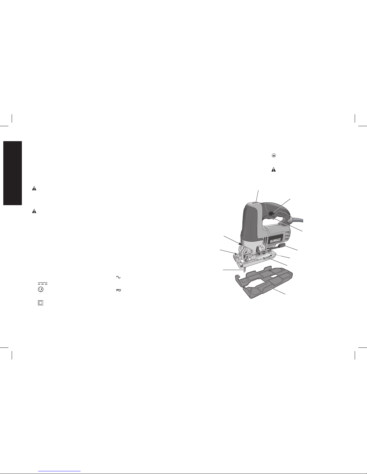
• Keep hands away from cutting area. Never reach underneath
the material for any reason. Hold front of saw by grasping the
contoured gripping area. Do not insert fingers or thumb into the
vicinity of the reciprocating blade and blade clamp. Do not stabilize
the saw by gripping the shoe.
• Keep blades sharp. Dull blades may cause the saw to swerve or
stall under pressure.
• When cutting pipe or conduit ensure that they are free from
water, electrical wiring, etc.
• Allow the motor to come to a complete stop before
withdrawing the blade from the kerf (the slot created by
cutting). A moving blade may impact the workpiece causing a
broken blade, workpiece damage or loss of control and possible
personal injury.
• Never hold work in your hand, lap or against parts of your
body when sawing. The saw may slip and the blade could
contact the body causing injury.
• Keep handles dry, clean, free from oil and grease. This will
enable better control of the tool.
• Clean out your tool often, especially after heavy use. Dust
and grit containing metal particles often accumulate on interior
surfaces and could create an electric shock hazard.
• Do not operate this tool for long periods of time. Vibration
caused by the operating action of this tool may cause permanent
injury to fingers, hands, and arms. Use gloves to provide extra
cushion, take frequent rest periods, and limit daily time of use.
• Avoid prolonged contact with dust from power sanding,
sawing, grinding, drilling, and other construction activities.
Wear protective clothing and wash exposed areas with
soap and water. Allowing dust to get into your mouth, eyes, or
lay on the skin may promote absorption of harmful chemicals.
WARNING: Wear appropriate hearing protection during use.
Under some conditions and duration of use, noise from this product
may contribute to hearing loss.
• Air vents often cover moving parts and should be avoided.
Loose clothes, jewelry or long hair can be caught in moving parts.
• An extension cord must have adequate wire size for safety.
An undersized cord will cause a drop in line voltage resulting in loss
of power and overheating. When using more than one extension
to make up the total length, be sure each individual extension
contains at least the minimum wire size. The following table shows
the correct size to use depending on cord length and nameplate
ampere rating. If in doubt, use the next heavier gauge. The smaller
the gauge number, the heavier the cord.
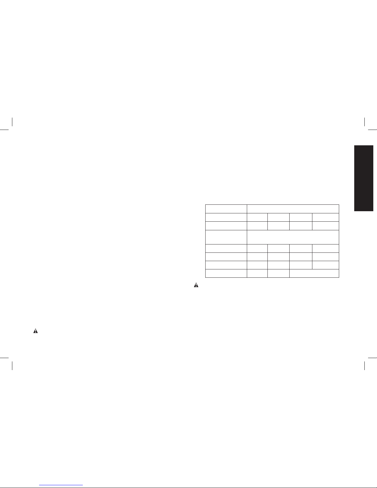
Voltage (Volts) Total length of cord in meters (m)
120–127V 0–7 7–15 15–30 30–50
220–240V 0–15 15–30 30–60 60–100
Rated Ampere
range
Minimal cross-sectional area of the
cord in meters (mm2)
0–6A 1.0 1.5 1.5 2.5
6–10A 1.0 1.5 2.5 4.0
10–12A 1.5 1.5 2.5 4.0
12–16A 2.5 4.0 Not Recommended
WARNING: Some dust created by power sanding, sawing,
grinding, drilling, and other construction activities contains chemicals
known to cause cancer, birth defects or other reproductive harm.
Some examples of these chemicals are:
• lead from lead-based paints,
• crystalline silica from bricks and cement and other masonry
products, and
• arsenic and chromium from chemically-treated lumber.
Your risk from these exposures varies, depending on how often you
do this type of work. To reduce your exposure to these chemicals:

4
English
work in a well ventilated area, and work with approved safety
equipment, such as those dust masks that are specially designed to
filter out microscopic particles.
• Avoid prolonged contact with dust from power sanding,
sawing, grinding, drilling, and other construction activities.
Wear protective clothing and wash exposed areas with
soap and water. Allowing dust to get into your mouth, eyes, or
lay on the skin may promote absorption of harmful chemicals.
WARNING: Use of this tool can generate and/or disburse dust,
which may cause serious and permanent respiratory or other injury.
Always use NIOSH/OSHA approved respiratory protection appropriate
for the dust exposure. Direct particles away from face and body.
WARNING: ALWAYS USE SAFETY GLASSES. Everyday
eyeglasses are NOT safety glasses. Also use face or dust mask if
cutting operation is dusty. ALL USERS AND BYSTANDERS MUST
ALWAYS WEAR CERTIFIED SAFETY EQUIPMENT:
• ANSI Z87.1 eye protection (CAN/CSA Z94.3),
• ANSI S12.6 (S3.19) hearing protection,
• NIOSH/OSHA/MSHA respiratory protection.
• The label on your tool may include the following symbols. The
symbols and their definitions are as follows:
V................... volts A......................amperes
Hz................. hertz W.....................watts
min ............... minutes or AC..........alternating
or DC... direct current current
................. Class I Construction or AC/DC...alternating
(grounded) ........................or direct
................. Class II Construction current
(double insulated) no....................no load
…/min .......... revolutions per minute .......................speed
BPM ............. beats per minute n ......................rated
IPM............... impacts per minute ........................speed
SPM ............. strokes per minute .....................earthing
sfpm ............. surface feet terminal
..................... per minute .....................safety alert
..................... symbol
FIG. 1
A
B
C
D
E
H
F
G
I
J

5
English
DESCRIPTION (FIG. 1)
WARNING: Never modify the power tool or any part of it. Damage
or personal injury could result.
A. Trigger switch G. Shoe beveling lever
B. Lock-on button H. Speed control wheel
C. Saw blade locking lever I. Cutting action lever
D. Saw blade J. LED Light
E. Shoe sleeve
F. Shoe
INTENDED USE
This jig saw is designed for professional sawing applications.
DO NOT use under wet conditions or in presence of flammable
liquids or gases.
This jig saw is a professional power tools. DO NOT let children come
into contact with the tool. Supervision is required when inexperienced
operators use this tool.
ASSEMBLY AND ADJUSTMENTS
WARNING: Prior to assembly and adjustment, ALWAYS unplug
tool.
OPERATION
WARNING: Always observe the safety instructions and applicable
regulations.
Blade Installation
FIG. 2
C
(Fig. 2)
1. Push the saw blade locking
lever (C) upward.
2. With teeth facing forward,
insert the shank of the saw
blade into the blade holder
as far as it will go.
3. Release the lever.
4. Check to ensure blade is secure before cutting.
Adjusting the Shoe for Bevel Cuts
(Fig. 3)
WARNING: Never use the tool when the shoe is loose or removed.
The shoe plate can be set to a left or right bevel angle of up to 45°.
TO SET THE BEVEL ANGLE
1. Pull the shoe beveling
FIG. 3
G
F
lever (G) out and away
from the saw to unlock
the shoe (F) as shown in
Figure 3.
2. Slide the shoe forward
to release it from the 0°
positive stop position.
3. The shoe can be beveled
to the left or to the right
and has detents at 15°,
30° and 45°.
4. Set the shoe to the desired bevel angle. Use a protractor to verify
angle accuracy.
5. Push the shoe beveling lever back towards the saw to lock the
shoe.
TO RESET THE SHOE FOR STRAIGHT CUTS
1. Pull the shoe beveling lever (G) out and away from the saw to
unlock the shoe (F) as shown in Figure 3.
2. Rotate shoe to an angle of approximately 0° and then pull shoe
backwards to engage the 0° positive stop.
3. Push the shoe beveling lever back towards the saw to lock the
shoe.

6
English
Switching On and Off
To switch the tool on, squeeze the trigger switch (A).
For continuous operation, squeeze the trigger switch then depress
the lock-on button (B). Once lock-on button is depressed, release the
trigger switch.
To switch the tool off, release the trigger switch. To switch the tool
off, when in continuous operation, squeeze the trigger and the lock
will disengage.
Variable Speed Control (Fig. 4)
A speed control wheel (H) is FIG. 4 H
located on the top of the saw. The
speed increases as the wheel is
turned from a low speed setting of
1 to a high speed setting of 7.
Cutting Action –
Orbital or Straight
(Fig. 5)
WARNING: Check that the tool is not locked ON before connecting
it to a power supply. If the trigger switch is locked on when the tool is
connected to the power supply, it will start immediately. Damage to
your tool or personal injury may result.
This jig saw is equipped with FIG. 5
four cutting actions, three orbital
and one straight. Orbital action
has a more aggressive blade
motion and is designed for cutting
in soft materials like wood or
plastic. Orbital action provides a
faster cut, but with a less smooth
cut across the material. In orbital
action, the blade moves forward during the cutting stroke in addition
to the up and down motion.
NOTE: Metal or hardwoods should never be cut in orbital action.
TO ADJUST THE CUTTING ACTION
1. Move the cutting action lever (I) between the four cutting
positions: 0, 1, 2, and 3.
2. Position 0 is straight cutting.
3. Positions 1, 2, and 3 are orbital cutting.
The aggressiveness of the cut increases as the lever is adjusted from
one to three, with three being the most aggressive cut.
LED Light
The jig saw is equipped with a light which projects on the cutting path.
The light will come on when the trigger switch is depressed and will
go off when the trigger switch is released.
Removable Shoe Sleeve (Fig. 6)
The non-marring shoe sleeve (E) should be used when cutting
surfaces that scratch easily, such as laminate, veneer, or paint. It can
also be used to protect the shoe surface during transportation and
storage.
To attach shoe sleeve, place FIG. 6
E
F
the front of the shoe (F) into
the front of the shoe sleeve
(E) and lower the jig saw as
shown in Figure 6. The shoe
sleeve will click securely onto
the rear of the shoe.
To remove shoe sleeve,
grasp the sleeve from the
bottom at the two rear tabs
and pull down and away from
the shoe.

7
English
Hints for Optimum Use
SAWING LAMINATES
As the saw blade cuts on the upward stroke, splintering may occur
on the surface closest to the shoe plate.
– Use a fine-tooth saw blade.
– Saw from the back surface of the workpiece.
– To minimize splintering, clamp a piece of scrap wood or
hardboard to both sides of the workpiece and saw through this
sandwich.
SAWING METAL
– Be aware that sawing metal takes much more time than sawing
wood.
– Use a saw blade suitable for sawing metal.
– When cutting thin metal, clamp a piece of scrap wood to the
back surface of the workpiece and cut through this sandwich.
– Spread a film of oil along the intended line of cut for easier
operation and longer blade life. For cutting aluminum, kerosene is
preferred.
Rip/Circle Cutting (Fig. 7, 8)
Ripping and circle cutting FIG. 7
K
without a pencil line are easily
done with the rip fence /
circle guide (not included;
available at extra cost).
Using the screw supplied
with the accessory guide,
position as shown in
Figure 7 and thread the
screw into the shoe to clamp
the fence securely.
When ripping, position as
J
FIG. 8
shown in Figure 7 and slide
the rip fence under the screw
from either side of the saw.
Set the cross bar (J) at
desired distance from blade
and tighten screw. For
ripping, the cross bar should
be down and against the
straight edge of the
workpiece as shown.
When circle cutting, adjust
rip fence so that distance
from blade to hole in fence
arm (K) is at the desired radius and tighten screw. Place saw so that
hole in fence arm is over center of circle to be cut (drill hole for blade
or cut inward from edge of material to get blade into position). When
saw is properly positioned, drive a small nail through hole in fence
arm. Using rip fence as a pivot arm, begin cutting circle. For circle
cutting, the cross bar should be up, as shown in Figure 8.
MAINTENANCE
WARNING: To reduce the risk of injury, turn unit off and
disconnect tool from power source before installing and
removing accessories, before making any adjustments or
removing/installing attachments or accessories. An accidental
start-up can cause injury.
Your D
e
WALT power tool has been designed to operate over a
long period of time with a minimum of maintenance. Continuous
satisfactory operation depends upon proper tool care and regular
cleaning.

8
English
Lubrication
Your power tool requires no additional lubrication.
Cleaning
WARNING: Blow dirt and dust out of the main housing with dry air
as often as dirt is seen collecting in and around the air vents. Wear
approved eye protection and approved dust mask when performing
this procedure.
WARNING: Never use solvents or other harsh chemicals for
cleaning the non-metallic parts of the tool. These chemicals may
weaken the materials used in these parts. Use a cloth dampened only
with water and mild soap. Never let any liquid get inside the tool;
never immerse any part of the tool into a liquid.
Repairs
To assure product SAFETY and RELIABILITY, repairs, maintenance
and adjustment (including brush inspection and replacement) should
be performed by authorized service centers or other qualified service
personnel, always using identical replacement parts.
Accessories
WARNING: Since accessories, other than those offered by
D
e
WALT, have not been tested with this product, use of such
accessories with this tool could be hazardous. To reduce the risk of
injury, only D
e
WALT, recommended accessories should be used with
this product.
Recommended accessories for use with your tool are available at extra
cost from your local dealer or authorized service center.
Protecting the Environment
Separate collection. This product must not be disposed of
with normal household waste.
Should you find one day that your
DeWALT
product needs
replacement, or if it is of no further use to you, do not dispose of it
with household waste.
Separate collection of used products and packaging allows
materials to be recycled and used again. Re-use of recycled
materials helps prevent environmental pollution and reduces
the demand for raw materials.
Local regulations may provide for separate collection of electrical
products from the household, at municipal waste sites or by the
retailer when you purchase a new product.
DeWALT
provides a facility for the collection and recycling of
DeWALT
products once they have reached the end of their working life. To take
advantage of this service please return your product to any authorized
service center that will collect them on our behalf.
You can check the location of your nearest authorized service center
by contacting your local
DeWALT
office. Alternatively, a service center
listing is included in the packaging of this product.
SPECIFICATIONS
DW300-B3
Volts 120V ~
Watts 500W
Hertz 50-60 Hz
RPM 0-3200/min

9
English
TROUBLESHOOTING
Problem Possible Cause Possible Solution
• Unit will not start. • Cord not plugged in.
• Circuit fuse is blown.
• Plug tool into a working outlet.
• Replace circuit fuse. (If the product
repeatedly causes the circuit fuse to blow,
discontinue use immediately and have it
serviced at a D
e
WALT service center or
authorized servicer.)
• Circuit breaker is tripped. • Reset circuit breaker. (If the product
repeatedly causes thecircuit breaker to
trip,discontinue use immediately and have
it serviced at a D
e
WALT service center or
authorized servicer.)
• Cord or switch is damaged. • Have cord or switch replaced at a
D
e
WALT Center or authorized servicer.

D
e
WALT Industrial Tool Co., 701 East Joppa Road, Towson, MD 21286
(SEP15) Part No. N440832 DW300 Copyright @ 2010, 2015 D
e
WALT
The following are trademarks for one or more D
e
WALT power tools: the yellow and black color scheme; the “D” shaped air intake grill; the
array of pyramids on the handgrip; the kit box configuration; and the array of lozenge-shaped humps on the surface of the tool.
MADE IN BRAZIL
SOLAMENTE PARA PROPÓSITO DE ARGENTINA:
IMPORTADO POR: BLACK & DECKER ARGENTINA S.A.
PACHECO TRADE CENTER
COLECTORA ESTE DE RUTA PANAMERICANA
KM. 32.0 EL TALAR DE PACHECO
PARTIDO DE TIGRE
BUENOS AIRES (B1618FBQ)
REPÚBLICA DE ARGENTINA
NO. DE IMPORTADOR: 1146/66
TEL. (011) 4726-4400
MANUFACTURED BY/FABRICADO POR:
BLACK & DECKER DO BRASIL LTDA.
ROD. BR 050, S/N° - KM 167
DIST. INDUSTRIAL II
UBERABA – MG – CEP: 38064-750
CNPJ: 53.296.273/0001-91
INSC. EST.: 701.948.711.00-98
S.A.C.: 0800-703-4644
SOLAMENTE PARA PROPÓSITO DE MÉXICO:
IMPORTADO POR: BLACK & DECKER S.A. DE C.V.
AVENIDA ANTONIO DOVALI JAIME, # 70 TORRE B PISO 9
COLONIA, SANTA FÉ
DELEGACIÓN ALVARO OBREGÓN
MÉXICO D. F.: 01210
TEL. (52) 555-326-7100
R.F.C.: BDE810626-1W7
MAQUINAS Y HERRAMIENTAS BLACK & DECKER CHILE S.A.
AVDA. EDUARDO FREI M. #6001 EDIFICIO 67
CONCHALI-SANTIAGO
CHILE
TEL: 56-2-26871706
Other manuals for DW300
1
Table of contents
Other DeWalt Power Tools manuals

DeWalt
DeWalt DPN46RN-XJ User manual

DeWalt
DeWalt DW685 User manual

DeWalt
DeWalt DW331 User manual

DeWalt
DeWalt DWE4202 User manual

DeWalt
DeWalt D26411-XE User manual

DeWalt
DeWalt DCF923 User manual

DeWalt
DeWalt XTREME DCD701 User manual

DeWalt
DeWalt XR DCS355N User manual

DeWalt
DeWalt D51430 User manual

DeWalt
DeWalt XR DCD1623 User manual

DeWalt
DeWalt DWE46172 User manual

DeWalt
DeWalt DCE530 User manual

DeWalt
DeWalt DCF894N User manual

DeWalt
DeWalt DCS335N User manual

DeWalt
DeWalt D25052 User manual

DeWalt
DeWalt D28106 User manual

DeWalt
DeWalt XR DCS334 User manual

DeWalt
DeWalt XR DCS355 User manual

DeWalt
DeWalt DW896 User manual

DeWalt
DeWalt XR DCH263DH User manual