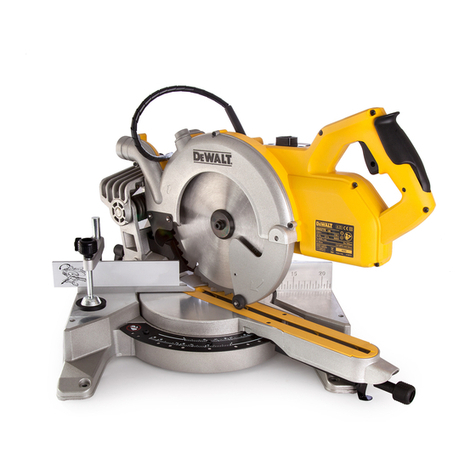
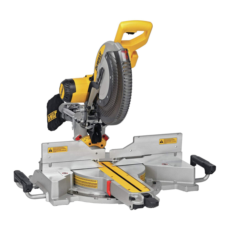
DeWalt DCS365 User manual

DCS365

B
Copyright DeWALT
English (original instructions) 6
Pусский (перевод соригинала инструкции) 16
Українська (переклад з оригінальної інструкції) 29

1
Fig. A
13 14
12
11
10
3 9 8 7 6
5
4
3
10
2
1
17
15
1
18 17
14
20
19 11
21
3
13
25
12
3
22
21
23
16
24

2
Fig. B Fig. C
Fig. D
Fig. F1
Fig. E
Fig. F3
16
26
44
Fig. F2
27
22
4
28
29
30
31
31
32
30
33
34
35
16
44
10

3
Fig. G1
Fig. H
Fig. G2
Fig. I
Fig. G3 Fig. G4
1
36
18
14
37
Fig. J
9
9
98 7 5
Fig. K

4
Fig. L1 Fig. L2
Fig. M Fig. N
Fig. O Fig. P
Fig. Q Fig. R
12
42
41
39
40
45º
48º
12
38
angle “A”
A
B
21
25

5
Fig. S Fig. T
Fig. U Fig. V
11
43
11
43
Fig. W Fig. X

6
ENGLISH
GENERAL POWER TOOL SAFETY WARNINGS
WARNING: Read all safety warnings, instructions, illustrations and specifications
provided with this power tool. Failure to follow all instructions listed below may result
in electric shock, fire and/or seriousinjury.
SAVE ALL WARNINGS AND INSTRUCTIONS
FOR FUTUREREFERENCE
The term “power tool” in the warnings refers to your mains‑operated (corded) power tool or
battery‑operated (cordless) powertool.
1) Work Area Safety
a ) Keep work area clean and well lit. Cluttered or dark areas inviteaccidents.
b ) Do not operate power tools in explosive atmospheres, such as in the presence of
flammable liquids, gases or dust. Power tools create sparks which may ignite the dust
orfumes.
c ) Keep children and bystanders away while operating a power tool. Distractions can
cause you to losecontrol.
2) Electrical Safety
a ) Power tool plugs must match the outlet. Never modify the plug in any way. Do
not use any adapter plugs with earthed (grounded) power tools. Unmodified plugs
and matching outlets will reduce risk of electricshock.
b ) Avoid body contact with earthed or grounded surfaces, such as pipes, radiators,
ranges and refrigerators. There is an increased risk of electric shock if your body is
earthed orgrounded.
c ) Do not expose power tools to rain or wet conditions. Water entering a power tool
will increase the risk of electricshock.
d ) Do not abuse the cord. Never use the cord for carrying, pulling or unplugging
the power tool. Keep cord away from heat, oil, sharp edges or moving parts.
Damaged or entangled cords increase the risk of electricshock.
e ) When operating a power tool outdoors, use an extension cord suitable for
outdoor use. Use of a cord suitable for outdoor use reduces the risk of electricshock.
f ) If operating a power tool in a damp location is unavoidable, use a residual
current device (RCD) protected supply. Use of an RCD reduces the risk of electricshock.
3) Personal Safety
a ) Stay alert, watch what you are doing and use common sense when operating a
power tool. Do not use a power tool while you are tired or under the influence of
drugs, alcohol or medication. A moment of inattention while operating power tools
may result in serious personalinjury.
b ) Use personal protective equipment. Always wear eye protection. Protective
equipment such as a dust mask, non‑skid safety shoes, hard hat or hearing protection
used for appropriate conditions will reduce personalinjuries.
c ) Prevent unintentional starting. Ensure the switch is in the off‑position before
connecting to power source and/or battery pack, picking up or carrying the tool.
Carrying power tools with your finger on the switch or energising power tools that have
the switch on invitesaccidents.
d ) Remove any adjusting key or wrench before turning the power tool on. A wrench
or a key left attached to a rotating part of the power tool may result in personalinjury.
e ) Do not overreach. Keep proper footing and balance at all times. This enables better
control of the power tool in unexpectedsituations.
f ) Dress properly. Do not wear loose clothing or jewellery. Keep your hair and
clothing away from moving parts. Loose clothes, jewellery or long hair can be caught
in movingparts.
aWARNING: To reduce the risk of injury, read the instructionmanual.
Definitions: Safety Guidelines
The definitions below describe the level of severity for each signal word. Please read the
manual and pay attention to thesesymbols.
DANGER: Indicates an imminently hazardous situation which, if not avoided, will result
in death or seriousinjury.
WARNING: Indicates a potentially hazardous situation which, if not avoided, could result
in death or seriousinjury.
CAUTION: Indicates a potentially hazardous situation which, if not avoided, may result
in minor or moderateinjury.
NOTICE: Indicates a practice not related to personal injury which, if not avoided, may
result in propertydamage.
Denotes risk of electricshock.
Denotes risk offire.
Markus Rompel
Vice‑President Engineering, PTE‑Europe
DeWALT, Richard‑Klinger‑Straße 11,
D‑65510, Idstein, Germany
01.11.2019
EC‑Declaration of Conformity
Machinery Directive
Mitre Saw
DCS365
DeWALT declares that these products described under Technical Data are in compliance with:
2006/42/EC, EN62841‑1:2015/AC:2015; EN62841‑3‑9:2015 + AC:2016 + A11:2017.
These products also comply with Directive 2014/30/EU and 2011/65/EU. For more information,
please contact DeWALT at the following address or refer to the back of themanual.
The undersigned is responsible for compilation of the technical file and makes this declaration
on behalf ofDeWALT.
The vibration and/or noise emission level given in this information sheet has been measured in
accordance with a standardised test given in EN
62841
and may be used to compare one tool
with another. It may be used for a preliminary assessment ofexposure.
WARNING: The declared vibration and/or noise emission level represents the main
applications of the tool. However if the tool is used for different applications, with different
accessories or poorly maintained, the vibration and/or noise emission may differ. This may
significantly increase the exposure level over the total workingperiod.
An estimation of the level of exposure to vibration and/or noise should also take into
account the times when the tool is switched off or when it is running but not actually doing
the job. This may significantly reduce the exposure level over the total workingperiod.
Identify additional safety measures to protect the operator from the effects of vibration
and/or noise such as: maintain the tool and the accessories, keep the hands warm
(relevant for vibration), organisation of workpatterns.
DCS365
Voltage VDC 18
Type 1
Battery type Li‑Ion
Blade diameter mm 184
Blade bore mm 16
Blade body thickness mm 1
Max. blade speed min‑1 3750
Max. cross‑cut capacity 90° mm 50
Max. mitre capacity 45° mm 35.3
Mitre (max. positions) left
right
45°
45°
Bevel (max. positions) left
right
48°
0°
0 ° mitre
Resulting width at max. height 50 mm
Resulting height at max. width 90 mm
mm
mm
250
15
45 ° mitre left
Resulting width at max. height 50 mm
Resulting height at max. width 90 mm
mm
mm
176
8
45 ° mitre right
Resulting width at max. height 50 mm
Resulting height at max. width 90 mm
mm
mm
176
8
45 ° bevel left
Resulting width at max. height 35 mm mm 250
Automatic blade brake time s< 10
Weight without battery kg 10.5
Noise values and/or vibration values (triax vector sum) according to EN62841‑3‑9:
LPA (emission sound pressure level) dB(A) 88
LWA (sound power level) dB(A) 93
K (uncertainty for the given sound level) dB(A) 2,0
Vibration emission value a
h
= m/s² <2,5
Uncertainty K = m/s² 1,5
Congratulations!
You have chosen a DeWALT tool. Years of experience, thorough product development and
innovation make DeWALT one of the most reliable partners for professional power toolusers.
Technical Data
English (original instructions)
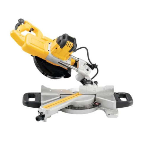
CORDLESS SLIDING COMPOUND MITRE SAW
DCS365

7
ENGLISH
etc. Abrasive dust causes moving parts such as the lower guard to jam. Sparks from
abrasive cutting will burn the lower guard, the kerf insert and other plasticparts.
b ) Use clamps to support the workpiece whenever possible. If supporting the
workpiece by hand, you must always keep your hand at least 100mm from either
side of the saw blade. Do not use this saw to cut pieces that are too small to be
securely clamped or held by hand. If your hand is placed too close to the saw blade,
there is an increased risk of injury from bladecontact.
c ) The workpiece must be stationary and clamped or held against both the fence
and the table. Do not feed the workpiece into the blade or cut “freehand” in any
way. Unrestrained or moving workpieces could be thrown at high speeds, causinginjury.
d ) Push the saw through the workpiece. Do not pull the saw through the workpiece.
To make a cut, raise the saw head and pull it out over the workpiece without
cutting, start the motor, press the saw head down and push the saw through the
workpiece. Cutting on the pull stroke is likely to cause the saw blade to climb on top of
the workpiece and violently throw the blade assembly towards theoperator.
e ) Never cross your hand over the intended line of cutting either in front or behind
the saw blade. Supporting the workpiece “cross handed” i.e. holding the workpiece to
the right of the saw blade with your left hand or vice versa is verydangerous.
f ) Do not reach behind the fence with either hand closer than 100mm from either
side of the saw blade, to remove wood scraps, or for any other reason while the
blade is spinning. The proximity of the spinning saw blade to your hand may not be
obvious and you may be seriouslyinjured.
g ) Inspect your workpiece before cutting. If the workpiece is bowed or warped,
clamp it with the outside bowed face toward the fence. Always make certain that
there is no gap between the workpiece, fence and table along the line of the cut.
Bent or warped workpieces can twist or shift and may cause binding on the spinning saw
blade while cutting. There should be no nails or foreign objects in theworkpiece.
h ) Do not use the saw until the table is clear of all tools, wood scraps, etc., except
for the workpiece. Small debris or loose pieces of wood or other objects that contact the
revolving blade can be thrown with highspeed.
i ) Cut only one workpiece at a time. Stacked multiple workpieces cannot be adequately
clamped or braced and may bind on the blade or shift duringcutting.
j ) Ensure the mitre saw is mounted or placed on a level, firm work surface before
use. A level and firm work surface reduces the risk of the mitre saw becomingunstable.
k ) Plan your work. Every time you change the bevel or mitre angle setting, make
sure the adjustable fence is set correctly to support the workpiece and will not
interfere with the blade or the guarding system. Without turning the tool “ON” and
with no workpiece on the table, move the saw blade through a complete simulated cut to
assure there will be no interference or danger of cutting thefence.
l ) Provide adequate support such as table extensions, saw horses, etc. for a
workpiece that is wider or longer than the table top. Workpieces longer or wider
than the mitre saw table can tip if not securely supported. If the cut‑off piece or workpiece
tips, it can lift the lower guard or be thrown by the spinningblade.
m ) Do not use another person as a substitute for a table extension or as additional
support. Unstable support for the workpiece can cause the blade to bind or the workpiece
to shift during the cutting operation pulling you and the helper into the spinningblade.
n ) The cut‑off piece must not be jammed or pressed by any means against the
spinning saw blade. If confined, i.e. using length stops, the cut‑off piece could get
wedged against the blade and thrownviolently.
o ) Always use a clamp or a fixture designed to properly support round material such
as rods or tubing. Rods have a tendency to roll while being cut, causing the blade to
“bite” and pull the work with your hand into theblade.
p ) Let the blade reach full speed before contacting the workpiece. This will reduce the
risk of the workpiece beingthrown.
q ) If the workpiece or blade becomes jammed, turn the mitre saw off. Wait for
all moving parts to stop and disconnect the plug from the power source and/
or remove the battery pack. Then work to free the jammed material. Continued
sawing with a jammed workpiece could cause loss of control or damage to the mitresaw.
r ) After finishing the cut, release the switch, hold the saw head down and wait for
the blade to stop before removing the cut‑off piece. Reaching with your hand near
the coasting blade isdangerous.
s ) Hold the handle firmly when making an incomplete cut or when releasing the
switch before the saw head is completely in the down position. The braking action
Safety Instructions for Mitre Saws
a ) Mitre saws are intended to cut wood or wood‑like products, they cannot be used
with abrasive cut‑off wheels for cutting ferrous material such as bars, rods, studs,
g ) If devices are provided for the connection of dust extraction and collection
facilities, ensure these are connected and properly used. Use of dust collection can
reduce dust‑relatedhazards.
h ) Do not let familiarity gained from frequent use of tools allow you to become
complacent and ignore tool safety principles. A careless action can cause severe
injury within a fraction of asecond.
4) Power Tool Use and Care
a ) Do not force the power tool. Use the correct power tool for your application. The
correct power tool will do the job better and safer at the rate for which it wasdesigned.
b ) Do not use the power tool if the switch does not turn it on and off. Any power tool
that cannot be controlled with the switch is dangerous and must berepaired.
c ) Disconnect the plug from the power source and/or remove the battery pack,
if detachable, from the power tool before making any adjustments, changing
accessories, or storing power tools. Such preventive safety measures reduce the risk of
starting the power toolaccidentally.
d ) Store idle power tools out of the reach of children and do not allow persons
unfamiliar with the power tool or these instructions to operate the power tool.
Power tools are dangerous in the hands of untrainedusers.
e ) Maintain power tools and accessories. Check for misalignment or binding of
moving parts, breakage of parts and any other condition that may affect the
power tool’s operation. If damaged, have the power tool repaired before use.
Many accidents are caused by poorly maintained powertools.
f ) Keep cutting tools sharp and clean. Properly maintained cutting tools with sharp
cutting edges are less likely to bind and are easier tocontrol.
g ) Use the power tool, accessories and tool bits etc. in accordance with these
instructions, taking into account the working conditions and the work to be
performed. Use of the power tool for operations different from those intended could
result in a hazardoussituation.
h ) Keep handles and grasping surfaces dry, clean and free from oil and grease.
Slippery handles and grasping surfaces do not allow for safe handling and control of the
tool in unexpectedsituations.
5) Battery Tool Use and Care
a ) Recharge only with the charger specified by the manufacturer. A charger that is
suitable for one type of battery pack may create a risk of fire when used with another
batterypack.
b ) Use power tools only with specifically designated battery packs. Use of any other
battery packs may create a risk of injury andfire.
c ) When battery pack is not in use, keep it away from other metal objects, like paper
clips, coins, keys, nails, screws or other small metal objects, that can make a
connection from one terminal to another. Shorting the battery terminals together
may cause burns or afire.
d ) Under abusive conditions, liquid may be ejected from the battery; avoid
contact. If contact accidentally occurs, flush with water. If liquid contacts eyes,
additionally seek medical help. Liquid ejected from the battery may cause irritation
orburns.
e ) Do not use a battery pack or tool that is damaged or modified. Damaged or
modified batteries may exhibit unpredictable behaviour resulting in fire, explosion or risk
ofinjury.
f ) Do not expose a battery pack or tool to fire or excessive temperature. Exposure to
fire or temperature above 130°C may causeexplosion.
g ) Follow all charging instructions and do not charge the battery pack or tool
outside the temperature range specified in the instructions. Charging improperly
or at temperatures outside the specified range may damage the battery and increase the
risk offire.
6) Service
a ) Have your power tool serviced by a qualified repair person using only identical
replacement parts. This will ensure that the safety of the power tool ismaintained.
b ) Never service damaged battery packs. Service of battery packs should only be
performed by the manufacturer or authorized serviceproviders.
Batteries Chargers/Charge Times (Minutes)
Cat # VDC Ah Weight (kg) DCB104 DCB107 DCB112 DCB113 DCB115 DCB116 DCB117 DCB118 DCB132 DCB119
DCB546 18/54 6.0/2.0 1.05 60 270 170 140 90 80 40 60 90 X
DCB547 18/54 9.0/3.0 1.46 75* 420 270 220 135* 110* 60 75* 135* X
DCB548 18/54 12.0/4.0 1.44 120 540 350 300 180 150 80 120 180 X
DCB181 18 1.5 0.35 22 70 45 35 22 22 22 22 22 45
DCB182 18 4.0 0.61 60/40** 185 120 100 60 60/45** 60/40** 60/40** 60 120
DCB183/B 18 2.0 0.40 30 90 60 50 30 30 30 30 30 60
DCB184/B 18 5.0 0.62 75/50** 240 150 120 75 75/60** 75/50** 75/50** 75 150
DCB185 18 1.3 0.35 22 60 40 30 22 22 22 22 22 X
DCB187 18 3.0 0.54 45 140 90 70 45 45 45 45 45 90
DCB189 18 4.0 0.54 60 185 120 100 60 60 60 60 60 120
*Date code 201811475B or later
**Date code 201536or later
Batteries
Chargers/Charge Times (Minutes)
Cat #
DC
Weight
*Date code 201811475B or later
**Date code 201536or later

8
ENGLISH
Chargers
DeWALT chargers require no adjustment and are designed to be as easy as possible tooperate.
Electrical Safety
The electric motor has been designed for one voltage only. Always check that the battery pack
voltage corresponds to the voltage on the rating plate. Also make sure that the voltage of your
charger corresponds to that of yourmains.
iYour DeWALT charger is double insulated in accordance with EN60335; therefore
no earth wire isrequired.
If the supply cord is damaged, it must be replaced only by DeWALT or an authorised
serviceorganisation.
Mains Plug Replacement
(U.K.& Ireland Only)
If a new mains plug needs to be fitted:
• Safely dispose of the oldplug.
• Connect the brown lead to the live terminal in theplug.
• Connect the blue lead to the neutralterminal.
WARNING: No connection is to be made to the earthterminal.
Follow the fitting instructions supplied with good quality plugs. Recommended fuse: 3A.
Using an Extension Cable
An extension cord should not be used unless absolutely necessary. Use an approved extension
cable suitable for the power input of your charger (see Technical Data). The minimum
conductor size is 1mm2; the maximum length is30m.
When using a cable reel, always unwind the cablecompletely.
Important Safety Instructions for All Battery Chargers
SAVE THESE INSTRUCTIONS: This manual contains important safety and operating
instructions for compatible battery chargers (refer to TechnicalData).
• Before using charger, read all instructions and cautionary markings on charger, battery pack,
and product using batterypack.
WARNING: Shock hazard. Do not allow any liquid to get inside charger. Electric shock
mayresult.
WARNING: We recommend the use of a residual current device with a residual current
rating of 30mA orless.
CAUTION: Burn hazard. To reduce the risk of injury, charge only DeWALT rechargeable
batteries. Other types of batteries may burst causing personal injury anddamage.
CAUTION: Children should be supervised to ensure that they do not play with
theappliance.
WARNING: We recommend the use of a residual current device with a residual current
rating of 30mA orless.
Residual Risks
The following risks are inherent to the use of saws:
• Injuries caused by touching the rotatingparts.
In spite of the application of the relevant safety regulations and the implementation of safety
devices, certain residual risks cannot be avoided. These are:
• Impairment ofhearing.
• Risk of accidents caused by the uncovered parts of the rotating sawblade.
• Risk of injury when changing theblade.
• Risk of squeezing fingers when opening theguards.
• Health hazards caused by breathing dust developed when sawing wood, especially oak,
beech andMDF.
The following factors increase the risk of breathing problems:
• No dust extractor connected when sawingwood.
• Insufficient dust extraction caused by uncleaned exhaustfilters.
SAVE THESE INSTRUCTIONS
WARNING: ALWAYS use safety glasses. Everyday eyeglasses are NOT safety glasses. Also
use face or dust mask if cutting operation isdusty.
WARNING: Use of this tool can generate and/or disperse dust, which may cause serious
and permanent respiratory or otherinjury.
WARNING: Some dust created by power sanding, sawing, grinding, drilling, and other
construction activities contains chemicals known to cause cancer, birth defects or other
reproductive harm. Some examples of these chemicals are:
• lead from lead‑based paints,
• crystalline silica from bricks and cement and other masonry products, and
• arsenic and chromium from chemically‑treatedlumber.
Your risk from these exposures varies, depending on how often you do this type of work. To reduce
your exposure to these chemicals: work in a well ventilated area, and work with approved safety
equipment, such as those dust masks that are specially designed to filter out microscopicparticles.
• Avoid prolonged contact with dust from power sanding, sawing, grinding, drilling,
and other construction activities. Wear protective clothing and wash exposed areas with
soap and water. Allowing dust to get into your mouth, eyes, or lay on the skin may promote
absorption of harmfulchemicals.
WARNING: Use of this tool can generate and/or disperse dust, which may cause serious
and permanent respiratory or other injury. Always use approved respiratory protection
appropriate for the dustexposure.
of the saw may cause the saw head to be suddenly pulled downward, causing a risk
ofinjury.
Additional Safety Rules for Mitre Saws
WARNING: Do not connect to the mains power supply into the unit until complete
instructions are read andunderstood.
• DO NOT OPERATE THIS MACHINE until it is completely assembled and installed according
to the instructions. A machine incorrectly assembled can cause seriousinjury.
• OBTAIN ADVICE from your supervisor, instructor, or another qualified person if you are not
thoroughly familiar with the operation of this machine. Knowledge issafety.
• MAKE CERTAIN the blade rotates in the correct direction. The teeth on the blade should point
in the direction of rotation as marked on thesaw.
• TIGHTEN ALL CLAMP HANDLES, knobs and levers prior to operation. Loose clamps can
cause parts or the workpiece to be thrown at highspeeds.
• BE SURE all blade and blade clamps are clean, recessed sides of blade clamps are against
blade and arbour screw is tightened securely. Loose or improper blade clamping may result in
damage to the saw and possible personalinjury.
• DO NOT OPERATE ON ANYTHING OTHER THAN THE DESIGNATED VOLTAGE for the saw.
Overheating, damage to the tool and personal injury mayoccur.
• DO NOT WEDGE ANYTHING AGAINST THE FAN to hold the motor shaft. Damage to tool
and possible personal injury mayoccur.
• NEVER CUT METALS or masonry. Either of these can cause the carbide tips to fly off the blade
at high speeds causing seriousinjury.
• NEVER HAVE ANY PART OF YOUR BODY IN LINE WITH THE PATH OF THE SAW BLADE.
Personal injury willoccur.
• NEVER APPLY BLADE LUBRICANT TO A RUNNING BLADE. Applying lubricant could cause
your hand to move into the blade resulting in seriousinjury.
• DO NOT place either hand in the blade area when the saw is connected to the power source.
Inadvertent blade activation may result in seriousinjury.
• NEVER REACH AROUND OR BEHIND THE SAW BLADE. A blade can cause seriousinjury.
• DO NOT REACH UNDERNEATH THE SAW unless it is unplugged and turned off. Contact
with saw blade may cause personalinjury.
• SECURE THE MACHINE TO A STABLE SUPPORTING SURFACE. Vibration can possibly
cause the machine to slide, walk, or tip over, causing seriousinjury.
• USE ONLY CROSSCUT SAW BLADES recommended for mitre saws. For best results, do not
use carbide tipped blades with hook angles in excess of 7degrees. Do not use blades with deep
gullets. These can deflect and contact the guard, and can cause damage to the machine and/
or seriousinjury.
• USE ONLY BLADES OF THE CORRECT SIZE AND TYPE specified for this tool to prevent
damage to the machine and/or serious injury (complying with EN847‑1).
• INSPECT BLADE FOR CRACKS or other damage prior to operation. A cracked or damaged
blade can come apart and pieces can be thrown at high speeds, causing serious injury.
Replace cracked or damaged blades immediately. Observe the maximum speed marked on
the sawblade.
• THE MAXIMUM SPEED OF THE SAW BLADE shall always be greater than or at least equal
to the speed marked on the rating plate of thetool.
• THE SAW BLADE DIAMETER must be in accordance with the markings on rating plate of
thetool.
• CLEAN THE BLADE AND BLADE CLAMPS prior to operation. Cleaning the blade and blade
clamps allows you to check for any damage to the blade or blade clamps. A cracked or
damaged blade or blade clamp can come apart and pieces can be thrown at high speeds,
causing seriousinjury.
• DO NOT USE WARPED BLADES. Check to see if the blade runs true and is free from vibration.
A vibrating blade can cause damage to the machine and/or seriousinjury.
• DO NOT use lubricants or cleaners (particularly spray or aerosol) in the vicinity of the plastic
guard. The polycarbonate material used in the guard is subject to attack by certainchemicals.
• KEEP GUARD IN PLACE and in workingorder.
• ALWAYS USE THE KERF PLATE AND REPLACE THIS PLATE WHEN DAMAGED. Small chip
accumulation under the saw may interfere with the saw blade or may cause instability of
workpiece whencutting.
• USE ONLY BLADE CLAMPS SPECIFIED FOR THIS TOOL to prevent damage to the machine
and/or seriousinjury.
• MAKE SURE to use the correct saw blade for the material to becut.
• CLEAN THE MOTOR AIR SLOTS of chips and sawdust. Clogged motor air slots can cause the
machine to overheat, damaging the machine and possibly causing a short which could cause
seriousinjury.
• NEVER LOCK THE SWITCH IN THE “ON” POSITION. Severe personal injury mayresult.
• NEVER STAND ON TOOL. Serious injury could occur if the tool is tipped or if the cutting tool
is unintentionallycontacted.
WARNING: Cutting plastics, sap coated wood, and other materials may cause melted
material to accumulate on the blade tips and the body of the saw blade, increasing the
risk of blade overheating and binding whilecutting.
WARNING: Always wear proper personal hearing protection. Under some
conditions and duration of use, noise from this product may contribute to hearing loss. Be
aware of the following factors influencing exposure to noise:
• Use saw blades designed to reduce the emitted noise,
• Use only well sharpened saw blades, and
• Use specifically designed noise‑reduction sawblades.

9
ENGLISH
Battery Packs
Important Safety Instructions for All Battery Packs
When ordering replacement battery packs, be sure to include catalogue number andvoltage.
The battery pack is not fully charged out of the carton. Before using the battery pack and
charger, read the safety instructions below. Then follow charging proceduresoutlined.
READ ALL INSTRUCTIONS
• Do not charge or use battery in explosive atmospheres, such as in the presence of
flammable liquids, gases or dust. Inserting or removing the battery from the charger may
ignite the dust orfumes.
• Never force battery pack into charger. Do not modify battery pack in any way to
fit into a non‑compatible charger as battery pack may rupture causing serious
personalinjury.
• Charge the battery packs only in DeWALTchargers.
• DO NOT splash or immerse in water or otherliquids.
• Do not store or use the tool and battery pack in locations where the temperature
may fall below 4˚C (34˚F) (such as outside sheds or metal buildings in winter), or
reach or exceed 40˚C (104˚F) (such as outside sheds or metal buildings insummer).
• Do not incinerate the battery pack even if it is severely damaged or is completely
worn out. The battery pack can explode in a fire. Toxic fumes and materials are created when
lithium‑ion battery packs areburned.
• If battery contents come into contact with the skin, immediately wash area with
mild soap and water. If battery liquid gets into the eye, rinse water over the open eye for
15minutes or until irritation ceases. If medical attention is needed, the battery electrolyte is
composed of a mixture of liquid organic carbonates and lithiumsalts.
• Contents of opened battery cells may cause respiratory irritation. Provide fresh air. If
symptoms persists, seek medicalattention.
WARNING: Burn hazard. Battery liquid may be flammable if exposed to spark orflame.
WARNING: Never attempt to open the battery pack for any reason. If battery pack case
is cracked or damaged, do not insert into charger. Do not crush, drop or damage battery
pack. Do not use a battery pack or charger that has received a sharp blow, been dropped,
run over or damaged in any way (i.e., pierced with a nail, hit with a hammer, stepped on).
Electric shock or electrocution may result. Damaged battery packs should be returned to
service centre forrecycling.
WARNING: Fire hazard. Do not store or carry the battery pack so that metal
objects can contact exposed battery terminals. For example, do not place the battery
pack in aprons, pockets, tool boxes, product kit boxes, drawers, etc., with loose nails,
screws, keys,etc.
CAUTION: When not in use, place tool on its side on a stable surface where it will
not cause a tripping or falling hazard. Some tools with large battery packs will stand
upright on the battery pack but may be easily knockedover.
Transportation
WARNING: Fire hazard. Transporting batteries can possibly cause fire if the battery
terminals inadvertently come in contact with conductive materials. When transporting
batteries, make sure that the battery terminals are protected and well insulated from
materials that could contact them and cause a short circuit. NOTE: Lithium‑ion batteries
should not be put in checkedbaggage.
DeWALT batteries comply with all applicable shipping regulations as prescribed by industry
and legal standards which include UN Recommendations on the Transport of Dangerous
Goods; International Air Transport Association (IATA) Dangerous Goods Regulations,
International Maritime Dangerous Goods (IMDG) Regulations, and the European Agreement
Concerning The International Carriage of Dangerous Goods by Road (ADR). Lithium‑ion cells
and batteries have been tested to section 38.3of the UN Recommendations on the Transport
of Dangerous Goods Manual of Tests andCriteria.
In most instances, shipping a DeWALT battery pack will be excepted from being classified as a
fully regulated Class 9Hazardous Material. In general, only shipments containing a lithium‑ion
battery with an energy rating greater than 100Watt Hours (Wh) will require being shipped
as fully regulated Class 9. All lithium‑ion batteries have the Watt Hour rating marked on the
Electronic Protection System
XR Li‑Ion tools are designed with an Electronic Protection System that will protect the battery
pack against overloading, overheating or deepdischarge.
The tool will automatically turn off if the Electronic Protection System engages. If this occurs,
place the lithium‑ion battery pack on the charger until it is fullycharged.
Wall Mounting
These chargers are designed to be wall mountable or to sit upright on a table or work surface.
If wall mounting, locate the charger within reach of an electrical outlet, and away from a
corner or other obstructions which may impede air flow. Use the back of the charger as a
template for the location of the mounting screws on the wall. Mount the charger securely
using drywall screws (purchased separately) at least 25.4mm long with a screw head diameter
of 7–9mm, screwed into wood to an optimal depth leaving approximately 5.5mm of the
screw exposed. Align the slots on the back of the charger with the exposed screws and fully
engage them in theslots.
Charger Cleaning Instructions
WARNING: Shock hazard. Disconnect the charger from the AC outlet before
cleaning. Dirt and grease may be removed from the exterior of the charger using a cloth
or soft non‑metallic brush. Do not use water or any cleaning solutions. Never let any liquid
get inside the tool; never immerse any part of the tool into aliquid.
NOTICE: Under certain conditions, with the charger plugged into the power supply, the
exposed charging contacts inside the charger can be shorted by foreign material. Foreign
materials of a conductive nature such as, but not limited to, steel wool, aluminum foil
or any buildup of metallic particles should be kept away from charger cavities. Always
unplug the charger from the power supply when there is no battery pack in the cavity.
Unplug charger before attempting toclean.
• DO NOT attempt to charge the battery pack with any chargers other than the ones in
this manual. The charger and battery pack are specifically designed to worktogether.
• These chargers are not intended for any uses other than charging DeWALT
rechargeable batteries. Any other uses may result in risk of fire, electric shock
orelectrocution.
• Do not expose charger to rain orsnow.
• Pull by plug rather than cord when disconnecting charger. This will reduce risk
ofdamage to electric plug andcord.
• Make sure that cord is located so that it will not be stepped on, tripped over, or
otherwise subjected to damage orstress.
• Do not use an extension cord unless it is absolutely necessary. Use of improper
extension cord could result in risk of fire,electric shock, orelectrocution.
• Do not place any object on top of charger or place the charger on a soft surface
that might block the ventilation slots and result in excessive internal heat. Place the
charger in a position away from any heat source. The charger is ventilated through slots in the
top and the bottom of thehousing.
• Do not operate charger with damaged cord or plug—have them replacedimmediately.
• Do not operate charger if it has received a sharp blow, been dropped, or otherwise
damaged in any way. Take it to an authorised servicecentre.
• Do not disassemble charger; take it to an authorised service centre when service or
repair is required. Incorrect reassembly may result in a risk of electric shock, electrocution
orfire.
• In case of damaged power supply cord, the supply cord must be replaced immediately by the
manufacturer, its service agent or similar qualified person to prevent anyhazard.
• Disconnect the charger from the outlet before attempting any cleaning. This will
reduce the risk of electric shock. Removing the battery pack will not reduce thisrisk.
• NEVER attempt to connect two chargerstogether.
• The charger is designed to operate on standard 230V household electrical power. Do
not attempt to use it on any other voltage. This does not apply to the vehicularcharger.
Charging a Battery (Fig.D)
1. Plug the charger into an appropriate outlet before inserting batterypack.
2. Insert the battery pack 16 into the charger, making sure the battery pack is fully seated
in the charger. The red (charging) light will blink repeatedly indicating that the charging
process hasstarted.
3. The completion of charge will be indicated by the red light remaining ON continuously.
The battery pack is fully charged and may be used at this time or left in the charger. To
remove the battery pack from the charger, push the battery release button 44 on the
batterypack.
NOTE: To ensure maximum performance and life of lithium‑ion battery packs, charge the
battery pack fully before firstuse.
Charger Operation
Refer to the indicators below for the charge status of the batterypack.
Charge Indicators
FCharging I
GFully Charged J
HHot/Cold Pack Delay* K
*The red light will continue to blink, but a yellow indicator light will be illuminated during this
operation. Once the battery pack has reached an appropriate temperature, the yellow light
will turn off and the charger will resume the chargingprocedure.
The compatible charger(s) will not charge a faulty battery pack. The charger will indicate faulty
battery by refusing tolight.
NOTE: This could also mean a problem with acharger.
If the charger indicates a problem, take the charger and battery pack to be tested at an
authorised servicecentre.
Hot/Cold Pack Delay
When the charger detects a battery pack that is too hot or too cold, it automatically starts a
Hot/Cold Pack Delay, suspending charging until the battery pack has reached an appropriate
temperature. The charger then automatically switches to the pack charging mode. This feature
ensures maximum battery packlife.
A cold battery pack will charge at a slower rate than a warm battery pack. The battery pack
will charge at that slower rate throughout the entire charging cycle and will not return to
maximum charge rate even if the battery packwarms.
The DCB118 charger is equipped with an internal fan designed to cool the battery pack. The
fan will turn on automatically when the battery pack needs to be cooled. Never operate the
charger if the fan does not operate properly or if ventilation slots are blocked. Do not permit
foreign objects to enter the interior of thecharger.

10
ENGLISH
Description (Fig.A)
WARNING: Never modify the power tool or any part of it. Damage or personal injury
couldresult.
1 Trigger switch
2 Operating handle
3 Mounting holes
4 Lower guard
5 Mitre lock knob
6 Kerf plate
7 Mitre arm
8 Mitre scale
9 Mitre scale screws
10 Side handles
11 Fence
12 Bevel lock knob
13 Rails
14 Dust port
15 Lifting handle
16 Battery pack
17 XPS™ worklight momentary switch
18 Lock off lever
19 Rail adjustment screw
20 Rail lock knob
21 Clamp hole
22 Blade wrench
23 Lock down pin
24 Date code
25 Bevel override
Intended Use
Your DeWALT DCS365 cordless sliding compound mitre saw has been designed for
professional wood cutting applications. It performs the sawing operations of cross‑cutting,
bevelling and mitring easily, accurately andsafely.
This unit is designed for use with a nominal blade diameter 184mm carbide tipblade.
NEVER CUT METALS or light alloy, especiallymagnesium.
DO NOT use under wet conditions or in the presence of flammable liquids orgases.
These mitre saws are professional power tools
DO NOT let children come into contact with the tool. Supervision is required when
inexperienced operators use thistool.
• Young children and the infirm. This appliance is not intended for use by young children
or infirm persons withoutsupervision.
• This product is not intended for use by persons (including children) suffering from
diminished physical, sensory or mental abilities; lack of experience, knowledge or skills
Date Code Position (Fig.A)
The date code 24, which also includes the year of manufacture, is printed into thehousing.
Example:
2020 XX XX
Year of Manufacture
Markings on Tool
The following pictograms are shown on the tool:
Read instruction manual beforeuse.
Wear earprotection.
Wear eyeprotection.
Keep hands away fromblade.
Visible radiation. Do not stare intolight.
Package Contents
The package contains:
1 Mitre saw
1 Blade wrench
1 Saw blade
1 Side handle package
1 Dustbag
1 Material clamp
1 Li‑Ion battery pack (C1, D1, L1, M1, P1, S1, T1, X1, Y1 models)
2 Li‑Ion battery packs (C2, D2, L2, M2, P2, S2, T2, X2, Y2 models)
3 Li‑Ion battery packs (C3, D3, L3, M3, P3, S3, T3, X3, Y3 models)
1 Instruction manual
NOTE: Battery packs, chargers and kitboxes are not included with N models. Battery packs and
chargers are not included with NT models. Bmodels include Bluetooth® batterypacks.
NOTE: The Bluetooth® word mark and logos are registered trademarks owned by the
Bluetooth®, SIG, Inc. and any use of such marks by DeWALT is under license. Other trademarks
and trade names are those of their respectiveowners.
• Check for damage to the tool, parts or accessories which may have occurred duringtransport.
• Take the time to thoroughly read and understand this manual prior tooperation.
Battery Type
The following SKU(s) operate on a 18 volt battery pack: DCS365
These battery packs may be used: DCB181, DCB182, DCB183, DCB183B, DCB184, DCB184B,
DCB185, DCB187, DCB189, DCB546, DCB547, DCB548. Refer to Technical Data for
moreinformation.
pack. Furthermore, due to regulation complexities, DeWALT does not recommend air shipping
lithium‑ion battery packs alone regardless of Watt Hour rating. Shipments of tools with
batteries (combo kits) can be air shipped as excepted if the Watt Hour rating of the battery
pack is no greater than 100Wh.
Regardless of whether a shipment is considered excepted or fully regulated, it is the
shipper's responsibility to consult the latest regulations for packaging, labeling/marking and
documentationrequirements.
The information provided in this section of the manual is provided in good faith and believed
to be accurate at the time the document was created. However, no warranty, expressed or
implied, is given. It is the buyer’s responsibility to ensure that its activities comply with the
applicableregulations.
Transporting the FLEXVOLTTM Battery
The DeWALT FLEXVOLTTM battery has two modes: Use andTransport.
Use Mode: When the FLEXVOLTTM battery stands alone or is in a DeWALT 18V product, it
will operate as an 18V battery. When the FLEXVOLTTM battery is in a 54V or a 108V (two 54V
batteries) product, it will operate as a 54Vbattery.
Transport Mode: When the cap is attached to the FLEXVOLTTM battery, the battery is in
Transport mode. Keep the cap forshipping.
When in Transport mode, strings of cells are electrically
disconnected within the pack resulting in 3batteries with a
lower Watt hour (Wh) rating as compared to 1battery with a
higher Watt hour rating. This increased quantity of 3batteries
with the lower Watt hour rating can exempt the pack from certain shipping regulations that
are imposed upon the higher Watt hour batteries.
For example, the Transport Wh rating might indicate
3x36Wh, meaning 3batteries of 36Wh each. The Use
Wh rating might indicate 108Wh (1batteryimplied).
Storage Recommendations
1. The best storage place is one that is cool and dry away from direct sunlight and excess
heat or cold. For optimum battery performance and life, store battery packs at room
temperature when not inuse.
2. For long storage, it is recommended to store a fully charged battery pack in a cool, dry
place out of the charger for optimalresults.
NOTE: Battery packs should not be stored completely depleted of charge. The battery pack
will need to be recharged beforeuse.
Labels on Charger and Battery Pack
In addition to the pictographs used in this manual, the labels on the charger and the battery
pack may show the following pictographs:
LRead instruction manual beforeuse.
p See Technical Data for chargingtime.
q Do not probe with conductiveobjects.
r Do not charge damaged batterypacks.
s Do not expose towater.
t Have defective cords replacedimmediately
u Charge only between 4˚C and 40˚C.
v Only for indooruse.
x Discard the battery pack with due care for theenvironment.
y Charge DeWALT battery packs only with designated DeWALT chargers. Charging
battery packs other than the designated DeWALT batteries with a DeWALT charger
may make them burst or lead to other dangeroussituations.
z Do not incinerate the batterypack.
B USE (without transport cap). Example: Wh rating indicates 108Wh (1battery with
108Wh).
A TRANSPORT (with built‑in transport cap). Example: Wh rating indicates 3x 36Wh
(3batteries of 36Wh).
Example of Use and Transport Label Marking

11
ENGLISH
Removing the Blade (Fig.A,C, F1–3)
1. Remove battery pack (16, Fig.C) from thesaw.
2. Raise the arm to the upper position and raise the lower guard4 as far aspossible.
3. Loosen, but do not remove the guard bracket rear screw27 by fourrevolutions.
4. Loosen, but do not remove the guard bracket front screw (28, Fig.F1) until the
bracket29 can be raised far enough to access the blade screw31. Lower guard will
remain raised due to the position of the guard bracketscrew.
5. Depress the spindle lock button (35, Fig.F2) while carefully rotating the saw blade30 by
hand until the lockengages.
6. Keeping the button depressed, use the other hand and the T40 side of the wrench
provided22 to loosen the blade screw31. (Turn clockwise, left‑hand threads.)
7. Remove the blade screw31 using the T40 side of the wrench provided, the outer clamp
washer(32, Fig.F3) and blade30. The inner clamp washer33 may be left on the
spindle34.
Installing a Blade (Fig.C,F1–F3)
1. Remove battery pack (16, Fig.C) from thesaw.
2. With the arm raised, the lower guard4 held open and the guard bracket29 raised, place
the blade30 on the spindle34 and against the inner clamp washer33 with the teeth
on the blade pointing in the direction of rotation as marked on thesaw.
3. Assemble the outer clamp washer32 onto the spindle34.
4. Install the blade screw31 and, engaging the spindle lock35, tighten the screw31
firmly with wrench22 provided (turn anticlockwise, left‑handthreads).
5. Return the guard bracket29 to its original full down position and firmly tighten both
guard bracket screws (27,28) to hold bracket inplace.
WARNING:The guard bracket must be returned to its original full down position and
the guard bracket screws tightened before activating the saw. Failure to do so may
prevent the guard from closing or may allow the guard to contact the spinning saw blade
resulting in damage to the saw and severe personalinjury.
Transporting the Saw (Fig.A)
WARNING: To reduce the risk of serious personal injury, turn tool off and
disconnect battery pack before making any adjustments, performing any
cleaning or maintenance, or removing/installing attachments or accessories. An
accidental start‑up can causeinjury.
WARNING:To reduce the risk of serious personal injury, always lock the rail lock knob20,
mitre lock knob5, bevel lock knob12 and lock down pin23 before transporting saw.
(Refer to FigureA.)
In order to conveniently carry the mitre saw from place to place, a lifting handle15 has been
included on the top of the saw arm and side handles10 on the base, as shown in FigureA.
Storage of Mitre Saw
The mitre saw must be stored in a dry place and locked up securely, out of reach of children or
untrainedpersons.
FEATURES AND CONTROLS
WARNING: To reduce the risk of serious personal injury, turn tool off and
disconnect battery pack before making any adjustments, performing any
cleaning or maintenance, or removing/installing attachments or accessories. An
accidental start‑up can causeinjury.
Use of XPS™LED Worklight System (Fig.A)
WARNING:Do not stare at operatinglamp.
NOTE: The battery must be charged and connected to the mitresaw.
The XPS™ LED Worklight System can be turned on by the momentary switch17. The light
will automatically turn off within 20seconds if the saw is not in use. The light is also activated
automatically every time the tool's main trigger1 ispulled.
To cut through an existing pencil line on a piece of wood, turn on the XPS™ worklight system
using the momentary switch17 (not with the main trigger), then pull down on the operating
handle2 to bring the saw blade close to the wood. The shadow of the blade will appear
on the wood. This shadow line represents the material that the blade will remove when
performing a cut. To correctly locate your cut to the pencil line, align the pencil line with the
edge of the blade’s shadow. Keep in mind that you may have to adjust the mitre or bevel
angles in order to match the pencil lineexactly.
Your saw is equipped with a battery fault feature. The XPS™ worklight begins to flash when the
battery is near the end of its useful charge, or when the battery is too hot. Charge the battery
prior to continuing cutting applications. Refer to Charging Procedure under Important
Safety Instructions for All Battery Packs for battery charginginstructions.
Mitre Lock Knob (Fig.A,J)
The mitre lock knob5 allows you to mitre your saw to 48° right and 48° left. The mitre latch
will automatically locate at 10˚, 15˚, 22.5˚, 31.62˚ and 45˚ both left andright.
Bevel Lock Knob (Fig.A,L1, L2)
The bevel lock allows you to bevel the saw 48° to the left. To adjust the bevel setting, turn the
bevel lock knob12 anticlockwise to loosen. To tighten, turn the bevel lock knobclockwise.
Rail Lock Knob (Fig.A)
The rail lock knob20 allows you to lock the saw head firmly to keep it from sliding on the rails.
This is necessary when making certain cuts or when transporting thesaw.
Familiarization (Fig.A,D, E)
Open the box and lift the saw out (Fig.D) by using the side hand indentations or lifting
handle15.
Place the saw on a smooth, flat surface such as a workbench or strongtable.
Examine FigureA to become familiar with the saw and its various parts. The section on
adjustments will refer to these terms and you must know what and where the partsare.
CAUTION: Pinch hazard. To reduce the risk of injury, keep thumb underneath the
operating handle when pulling the handle down. The lower guard will move up as the
operating handle is pulled down, which could cause pinching. The operating handle is
placed close to the guard for specialcuts.
Press down lightly on the operating handle2 and pull out the lock down pin23. Gently
release the downward pressure and hold the operating handle, allowing it to rise to its full
height. Use the lock down pin when carrying the saw from one place to another. Always use
the hand indentations or side handles10 to transport the saw as seen in FigureD. Refer to
FigureE and Installing SideHandles.
Installing Side Handles (Fig.E)
Your saw comes with two side handles10 that need to be installed onto the saw as shown in
FigureE. Use the 4screws and 4nuts provided. Tighten securely with the hex wrench found in
the side handlepackage.
Bench Mounting (Fig.A)
Holes3 are provided in all 4feet to facilitate bench mounting, as shown in FigureA. Always
mount your saw firmly to a stable surface to prevent movement. To enhance the tool’s
portability, it can be mounted to a piece of 12.7 mm or thicker plywood which can then be
clamped to your work support or moved to other job sites andreclamped.
NOTE: If you elect to mount your saw to a piece of plywood, make sure that the mounting
screws don’t protrude from the bottom of the wood. The plywood must sit flush on the work
support. When clamping the saw to any work surface, clamp only on the clamping bosses
where the mounting screw holes are located. Clamping at any other point will interfere with
the proper operation of thesaw.
CAUTION: To prevent binding and inaccuracy, be sure the mounting surface is not
warped or otherwise uneven. If the saw rocks on the surface, place a thin piece of material
under one saw foot until the saw sits firmly on the mountingsurface.
Changing or Installing a New Saw Blade (Fig.F1–F3)
Refer to Saw Blades under OptionalAccessories.
WARNING: To reduce the risk of serious personal injury, turn tool off and
disconnect battery pack before making any adjustments, performing any
cleaning or maintenance, or removing/installing attachments or accessories. An
accidental start‑up can causeinjury.
WARNING:To reduce the risk of injury, wear gloves when handling the sawblade.
CAUTION:
• Never depress the spindle lock button (35, Fig.F2) while the blade is under power
orcoasting.
• Do not cut metal, masonry or fiber cement product with this mitresaw.
Inserting and Removing the Battery Pack from the Tool (Fig.B)
NOTE: Make sure your battery pack 16 is fullycharged.
To Install the Battery Pack into the Tool Handle
1. Align the battery pack 16 with the rails inside the tool’s handle (Fig. B).
2. Slide it into the handle until the battery pack is firmly seated in the tool and ensure that
you hear the lock snap intoplace.
To Remove the Battery Pack from the Tool
1. Press the release button 44 and firmly pull the battery pack out of the toolhandle.
2. Insert battery pack into the charger as described in the charger section of thismanual.
Fuel Gauge Battery Packs (Fig.B)
Some DeWALT battery packs include a fuel gauge which consists of three green LED lights that
indicate the level of charge remaining in the batterypack.
To actuate the fuel gauge, press and hold the fuel gauge button 26. A combination of the
three green LED lights will illuminate designating the level of charge left. When the level of
charge in the battery is below the usable limit, the fuel gauge will not illuminate and the
battery will need to berecharged.
NOTE: The fuel gauge is only an indication of the charge left on the battery pack. It does
not indicate tool functionality and is subject to variation based on product components,
temperature and end‑userapplication.
ASSEMBLY AND ADJUSTMENTS
WARNING: To reduce the risk of serious personal injury, turn tool off and
disconnect battery pack before making any adjustments or removing/installing
attachments or accessories. An accidental start‑up can causeinjury.
WARNING: Use only DeWALT battery packs andchargers.
unless they are supervised by a person responsible for their safety. Children should never
be left alone with thisproduct.

12
ENGLISH
NOTE: DO NOT CUT METALS OR MASONRY WITH THIS SAW. Do not use any
abrasiveblades.
NOTE: Refer to Guard Actuation and Visibility in the Adjustments section for important
information about the lower guard beforecutting.
Crosscuts
Straight Cut (Fig.A, G1, G2)
A crosscut is made by cutting wood across the grain at any angle. A straight crosscut is made
with the mitre arm at the zero degree position. Set and lock the mitre arm at zero, hold the
wood firmly on the table and against the fence. With the rail lock knob20 tightened, turn on
the saw by squeezing the trigger switch1.
When the saw comes up to speed (about 1second) lower the arm smoothly and slowly to cut
through the wood. Let the blade come to a full stop before raisingarm.
When cutting anything larger than a 51mm x 102mm, use an out‑down‑back motion with
the rail lock knob20 loosened. Pull the saw out, toward you, lower the saw head down
toward the workpiece, and slowly push the saw back to complete the cut. Do not allow the
saw blade to contact the top of the workpiece while pulling out. The saw may run toward you,
possibly causing personal injury or damage to theworkpiece.
WARNING:Always use a work clamp to maintain control and reduce the risk of
workpiece damage and personal injury, if your hands are required to be within 100mm of
the blade during thecut.
NOTE: The rail lock knob20 shown in FigureA must be loose to allow the saw to slide along
itsrails.
Mitre Cuts (Fig.J,K)
Mitre crosscuts are made with the mitre arm at some angle other than zero. This angle is often
45º for making corners, but can be set anywhere from zero to 48º left or 48° right. To mitre the
saw, loosen the mitre lock knob5 by turning it anticlockwise. Pull up on the mitre lock knob
to move the mitre arm7 to the mitre angle desired on the mitre scale8. Turn the mitre lock
knob clockwise to tighten. Make the cut as describedabove.
When performing a mitre cut on workpieces wider than 51mm x 102mm that are shorter in
length, always place the longer side against the fence (Fig.K).
To cut through an existing pencil line on a piece of wood, match the angle as close as possible.
Cut the wood a little too long and measure from the pencil line to the cut edge to determine
which direction to adjust the mitre angle and recut. This will take some practice, but it is a
commonly usedtechnique.
Bevel Cuts (Fig.L1, L2)
A bevel cut is a crosscut made with the saw blade leaning at an angle to the wood. In order to
set the bevel, loosen the bevel lock knob12, and move the saw to the left as desired. Once
the desired bevel angle has been set, tighten the bevel lock firmly. Bevel angles can be set
from 0º right to 48ºleft.
To set the bevel angle past 45º to 48º,
1. Loosen the bevel lock knob12.
2. Tilt the saw head slightly to slide the bevel override25 to oneside.
3. Move the saw head to48º.
4. Tighten the bevel lockknob.
Quality of Cut
The smoothness of any cut depends on a number of variables. Things like material being cut,
blade type, blade sharpness and rate of cut all contribute to the quality of thecut.
When smoothest cuts are desired for molding and other precision work, a sharp (60 tooth
carbide tip) blade and a slower, even cutting rate will produce the desiredresults.
Ensure that the material does not move or creep while cutting; clamp it securely in place.
Always let the blade come to a full stop before raisingarm.
If small fibers of wood still split out at the rear of the workpiece, stick a piece of masking tape
on the wood where the cut will be made. Saw through the tape and carefully remove tape
whenfinished.
For varied cutting applications, refer to the list of recommended saw blades for your saw and
select the one that best fits your needs. Refer to Saw Blades under OptionalAccessories.
Clamping the Workpiece
WARNING: To reduce the risk of serious personal injury, turn tool off and
disconnect battery pack before making any adjustments, performing any
cleaning or maintenance, or removing/installing attachments or accessories. An
accidental start‑up can causeinjury.
WARNING:A workpiece that is clamped, balanced and secure before a cut may become
unbalanced after a cut is completed. An unbalanced load may tip the saw or anything the
saw is attached to, such as a table or workbench. When making a cut that may become
unbalanced, properly support the workpiece and ensure the saw is firmly bolted to a
stable surface. Personal injury mayoccur.
WARNING:The clamp foot must remain clamped above the base of the saw whenever
the clamp is used. Always clamp the workpiece to the base of the saw – not to any other
part of the work area. Ensure the clamp foot is not clamped on the edge of the base of
thesaw.
WARNING:Always use a work clamp to maintain control and reduce the risk of
workpiece damage and personal injury, if your hands are required to be within 100mm of
the blade during thecut.
If you cannot secure the workpiece on the table and against the fence by hand (irregular
shape, etc.), or your hand would be less than 100mm from the blade, a clamp or other fixture
must beused.
OPERATION
Instructions for Use
WARNING: Always observe the safety instructions and applicableregulations.
WARNING: To reduce the risk of serious personal injury, turn tool off and
disconnect battery pack before making any adjustments, performing any
cleaning or maintenance, or removing/installing attachments or accessories. An
accidental start‑up can causeinjury.
WARNING:To ensure the blade path is clear of obstructions, always make a dry run of the
cut without power before making any cuts on theworkpiece.
Proper Body and Hand Position (Fig.G1–G4)
WARNING: To reduce the risk of serious personal injury, ALWAYS use proper hand
position as shown in Fig.G1 andG2.
WARNING: To reduce the risk of serious personal injury, ALWAYS hold securely in
anticipation of a suddenreaction.
• Add clamps to support the workpiece wheneverpossible.
• Never place hands near cutting area. Place hands no closer than 100mm from
theblade.
• Hold the workpiece tightly to the table and the fence when cutting. Keep hands in
position until the trigger has been released and the blade has completelystopped.
• ALWAYS MAKE DRY RUNS (UNPOWERED) BEFORE FINISH CUTS SO THAT YOU CAN
CHECK THE PATH OF THE BLADE. DO NOT CROSS HANDS, AS SHOWN IN FIGURES G3
ANDG4.
• Keep both feet firmly on the floor and maintain proper balance. As you move the mitre
arm left and right, follow it and stand slightly to the side of the sawblade.
• Sight through the guard louvers when following a pencilline.
Trigger Switch (Fig.H)
To turn the saw on, push the lock‑off lever18 to the left, then depress the trigger switch1.
The saw will run while the switch is depressed. Allow the blade to spin up to full operating
speed before making the cut. To turn the saw off, release the switch. Allow the blade to stop
before raising the saw head. There is no provision for locking the switch on. A hole36 is
provided in the trigger for insertion of a padlock to lock the switchoff.
Your saw is not equipped with an automatic electric blade brake, but the saw blade should
stop within 5seconds of trigger release. This is not adjustable. If the stop time repeatedly
exceeds 5seconds, have the tool serviced by an authorised DeWALT servicecentre.
Always be sure the blade has stopped before removing it from thekerf.
Dust Extraction (Fig.A,I)
WARNING: To reduce the risk of serious personal injury, turn tool off and
disconnect battery pack before making any adjustments, performing any
cleaning or maintenance, or removing/installing attachments or accessories. An
accidental start‑up can causeinjury.
WARNING:Certain dust, such as oak or beech dust, is considered carcinogenic,
especially in connection with wood‑treatmentadditives.
• Always use dustextraction.
• Provide for good ventilation of the workspace.
• It is recommended to wear an appropriaterespirator.
Your saw has a built‑in dust port14 that allows either the supplied dust bag37 or a shop
vacuum system to beconnected.
To Attach the Dust Bag
1. Fit the dust bag37 to the dust port14 as shown in FigureI.
To Empty the Dust Bag
1. Remove dust bag37 from the saw and gently shake or tap the dust bag toempty.
2. Reattach the dust bag back onto the dust port14.
You may notice that all the dust will not come free from the bag. This will not affect cutting
performance but will reduce the saw's dust collection efficiency. To restore your saw's dust
collection efficiency, depress the spring inside the dust bag when you are emptying it and tap
it on the side of the trash can or dustreceptacle.
CAUTION:Never operate this saw unless the dust bag or DeWALT dust extractor is
in place. Wood dust may create a breathinghazard.
Cutting with your Saw (Fig.A)
If you cannot secure the workpiece on the table and against the fence by hand (irregular
shape, etc.), or your hand would be less than 100mm from the blade, a clamp or other fixture
must be used. Refer to Clamping the Workpiece for moreinformation.
If the slide feature is not used, ensure the saw head is pushed back as far as possible and the
rail lock knob20 is tightened. This will prevent the saw from sliding along its rails as the
workpiece isengaged.
Lock Down Pin (Fig.A)
WARNING:The lock down pin should be used only when carrying or storing the saw.
NEVER use the lock down pin for any cuttingoperation.
To lock the saw head in the down position, push the saw head down, push the lock down
pin23 in and release the saw head. This will hold the saw head safely down for moving the
saw from place to place. To release, press the saw head down and pull the pinout.

13
ENGLISH
Never use another person as a substitute for a table extension, as additional support for a
workpiece that is longer or wider than the basic mitre saw table or to help feed, support or pull
theworkpiece.
Support long workpieces using any convenient means such as sawhorses or similar devices to
keep the ends fromdropping.
Cutting Picture Frames, Shadow Boxes And Other Four‑Sided
Projects (Fig.P,Q)
To best understand how to make the items listed here, we suggest that you try a few simple
projects using scrap wood until you develop a “feel” for yoursaw.
Your saw is the perfect tool for mitring corners like the one shown in FigureP. Sketch A in
FigureQ shows a joint made by using the bevel adjustment to bevel the edges of the two
boards at 45º each to produce a 90º corner. For this joint the mitre arm was locked in the zero
position and the bevel adjustment was locked at 45º. The wood was positioned with the broad
flat side against the table and the narrow edge against the fence. The cut could also be made
by mitring right and left with the broad surface against thefence.
Cutting Trim Molding and Other Frames (Fig.Q)
Sketch B in FigureQ shows a joint made by setting the mitre arm at 45º to mitre the two
boards to form a 90º corner. To make this type of joint, set the bevel adjustment to zero and
the mitre arm to 45º. Once again, position the wood with the broad flat side on the table and
the narrow edge against thefence.
Figures P and Q are for four‑sided objectsonly.
As the number of sides changes, so do the mitre and bevel angles. The chart below gives the
proper angles for a variety ofshapes.
– EXAMPLES –
NUMBER OF SIDES MITRE OR BEVEL ANGLE
445°
536°
630°
725.7°
822.5°
920°
10 18°
The chart assumes that all sides are of equal length. For a shape that is not shown in the
chart, use the following formula: 180º divided by the number of sides equals the mitre (if the
material is cut vertically) or bevel angle (if the material is cut layingflat).
Cutting Compound Mitres (Fig.R)
A compound mitre is a cut made using a mitre angle and a bevel angle at the same time.
This is the type of cut used to make frames or boxes with slanting sides like the one shown in
FigureR.
NOTE: If the cutting angle varies from cut to cut, check that the bevel lock knob and the mitre
lock handle are securely locked. These must be locked after making any changes in bevel
ormitre.
The table below will assist you in selecting the proper bevel and mitre settings for common
compound mitre cuts. To use the chart, select the desired angleA (Fig.R) of your project and
locate that angle on the appropriate arc in the chart. From that point follow the chart straight
down to find the correct bevel angle and straight across to find the correct mitreangle.
Set your saw to the prescribed angles and make a few trial cuts. Practice fitting the cut pieces
together until you develop a feel for this procedure and feel comfortable withit.
Example: To make a 4‑sided box with 26º exterior angles (Angle A, Fig.R), use the upper right
arc. Find 26° on the arc scale. Follow the horizontal intersecting line to either side to get mitre
angle setting on saw (42°). Likewise, follow the vertical intersecting line to the top or bottom
to get the bevel angle setting on the saw (18°). Always try cuts on a few scrap pieces of wood
to verify the settings on thesaw.
SET THIS BEVEL ANGLE ON SAW
SET THIS MITER ANGLE ON SAW
ANGLE OF SIDE OF BOX (ANGLE "A")
SQUARE BOX
6 SIDED BOX
8 SIDED BOX
Use the material clamp provided with your saw. To purchase a material clamp, contact your
local retailer or DeWALT servicecentre.
Other aids such as spring clamps, bar clamps or C‑clamps may be appropriate for certain sizes
and shapes of material. Use care in selecting and placing these clamps. Take time to make a
dry run before making thecut.
To Install Clamp (Fig.M)
1. With the clamp38 facing the back of the mitre saw, insert the clamp rod into the hole21
behind the fence. Ensure the groove at the bottom of the clamp rod is fully inserted into
the hole21.
2. Rotate the clamp 180º toward the front of the mitresaw.
3. Loosen the knob to adjust the clamp arm up or down, then use the fine adjust knob to
firmly clamp theworkpiece.
NOTE: Place the clamp on the opposite side of the base when beveling. ALWAYS MAKE DRY
RUNS (UNPOWERED) BEFORE FINISH CUTS TO CHECK THE PATH OF THE BLADE. ENSURE THE
CLAMP DOES NOT INTERFERE WITH THE ACTION OF THE SAW ORGUARDS.
ADJUSTMENTS
WARNING: To reduce the risk of serious personal injury, turn tool off and
disconnect battery pack before making any adjustments, performing any
cleaning or maintenance, or removing/installing attachments or accessories. An
accidental start‑up can causeinjury.
Your mitre saw is fully and accurately adjusted at the factory at the time of manufacture.
If readjustment due to shipping and handling or any other reason is required, follow the
instructions below to adjust yoursaw.
Once made, these adjustments should remain accurate. Take a little time now to follow these
directions carefully to maintain the accuracy of which your saw iscapable.
Mitre Scale Adjustment (Fig.J,N)
Lock the saw head in the down position. Unlock the mitre lock knob5 and swing the mitre
arm7 until it locks at the 0° mitre position. Do not lock the mitre lock knob. Place a square
against the saw’s fence and blade, as shown in FigureN. (Do not touch the tips of the blade
teeth with the square. To do so will cause an inaccurate measurement.) If the saw blade is
not exactly perpendicular to the fence, loosen the three screws (9, Fig.J) that hold the mitre
scale8 and move the mitre arm and the scale left or right until the blade is perpendicular to
the fence, as measured with the square. Retighten the threescrews.
Bevel Square to Table Adjustment (Fig.A, L1,O)
To align the blade square to the table, lock the operating handle in the down position with
the lock down pin23. Place a square against the blade, ensuring the square is not on top
of a tooth. Loosen the bevel lock knob12 and ensure the bevel arm is firmly against the 0°
bevel stop. Rotate the 0° bevel adjustment screw41 with a 4mm hex key (not provided) as
necessary so that the blade is at 0° bevel to the table, as measured with thesquare.
Bevel Stop 45º Left Adjustment (Fig.A,L1, L2)
To adjust the left 45° bevel stop, first loosen the bevel lock knob and tilt the head until it stops.
Verify that the bevel override25 is in the 45° position; and if the bevel pointer40 does not
indicate exactly 45°, turn the 45° bevel adjustment screw42 until the bevel pointer40
reads 45°.
Guard Actuation and Visibility (Fig.A,X)
CAUTION:Pinch hazard. To reduce the risk of injury, keep thumb underneath the
operating handle when pulling the handle down. The lower guard will move up as the
operating handle is pulled down, which could causepinching.
The lower guard4 on your saw has been designed to automatically uncover the blade when
the arm is brought down and to cover the blade when the arm israised.
Before each use or after making adjustments, cycle the arm (unpowered) and make sure the
guard opens smoothly and closes fully. It should not contact the blade. With the arm up, raise
the guard (unpowered) as shown in FigureX and release. The guard should fully close rapidly.
Do not operate the saw if the guard does not move freely and fully close rapidly. Never clamp
or tie the guard in an open position when operating thesaw.
The guard can be raised by hand when installing or removing saw blades or for inspection of
the saw. NEVER RAISE THE lower GUARD MANUALLY UNLESS THE BLADE ISSTOPPED.
NOTE: Certain special cuts of large material will require that you manually raise the guard.
Refer to Cutting Large Material under SpecialCuts.
The front section of the guard is louvered for visibility while cutting. Although the louvers
dramatically reduce flying debris, there are openings in the guard and safety glasses should be
worn at alltimes.
Rail Guide Adjustment (Fig.A)
Periodically check the rails13 for any play or clearance. The rails can be cleaned with a
dry clean cloth. The right rail can be adjusted with the rail adjustment screw19 shown in
FigureA. To reduce clearance, use a 4mm hex wrench and rotate the set screw clockwise
gradually while sliding the saw head back and forth. Reduce play while maintaining minimum
slideforce.
Support for Long Pieces
WARNING: To reduce the risk of serious personal injury, turn tool off and
disconnect battery pack before making any adjustments, performing any
cleaning or maintenance, or removing/installing attachments or accessories. An
accidental start‑up can causeinjury.
ALWAYS SUPPORT LONGPIECES.

14
ENGLISH
Protecting the Environment
wSeparate collection. Products and batteries marked with this symbol must not be
disposed of with normal householdwaste.
Products and batteries contain materials that can be recovered or recycled reducing
the demand for raw materials. Please recycle electrical products and batteries
according to local provisions. Further information is available at www.2helpU.com.
Optional Accessories
WARNING: Since accessories, other than those offered by DeWALT, have not been tested
with this product, use of such accessories with this tool could be hazardous. To reduce the
risk of injury, only DeWALT recommended accessories should be used with thisproduct..
The following accessories, designed for your saw, may be helpful. In some cases, other
locally obtained work supports, length stops, clamps, etc., may be more appropriate. Use
care in selecting and using accessories. Consult your dealer for further information on the
appropriateaccessories.
Saw Blades
ONLY USE 184mm SAW BLADES WITH 16mm DIAMETER ROUND ARBOR HOLES and a
maximum KERF of 2.1mm. SPEED RATING MUST BE AT LEAST 4000RPM. DO NOT USE
BLADES WITH DIAMOND‑SHAPED ARBOR HOLES. Never use a different diameter blade. It will
not be guarded properly. Use crosscut blades only! Do not use blades designed for ripping,
combination blades or blades with hook angles in excess of 7°.
BLADE DESCRIPTIONS
APPLICATION DIAMETER TEETH
General Purpose 184 mm 40
Fine Woodcutting 184 mm 60
D
Cleaning
WARNING: Blow dirt and dust out of the main housing with dry air as often as dirt is seen
collecting in and around the air vents. Wear approved eye protection and approved dust
mask when performing thisprocedure.
WARNING: Never use solvents or other harsh chemicals for cleaning the non‑metallic
parts of the tool. These chemicals may weaken the materials used in these parts. Use a
cloth dampened only with water and mild soap. Never let any liquid get inside the tool;
never immerse any part of the tool into aliquid.
C
Lubrication
Your power tool requires no additionallubrication.
MAINTENANCE
Your power tool has been designed to operate over a long period of time with a minimum
of maintenance. Continuous satisfactory operation depends upon proper tool care and
regularcleaning.
WARNING: To reduce the risk of serious personal injury, turn tool off and
disconnect battery pack before making any adjustments or removing/installing
attachments or accessories. An accidental start‑up can causeinjury.
The charger and battery pack are notserviceable.
INSIDE CORNER OUTSIDE CORNER
Left side Mitre right at 45°
Save right side of cut
Mitre left at 45°
Save right side of cut
Right side Mitre left at 45°
Save left side of cut
Mitre right at 45°
Save left side of cut
Special Cuts
NEVER MAKE ANY CUT UNLESS THE MATERIAL IS SECURED ON THE TABLE AND AGAINST
THEFENCE.
Bowed Material (Fig.V,W)
When cutting bowed material always position it as shown in FigureV and never like that
shown in FigureW. Positioning the material incorrectly will cause it to pinch the blade near the
completion of thecut.
Cutting Round Material
ROUNDED MATERIAL SHOULD BE CLAMPED OR HELD FIRMLY TO THE FENCE TO KEEP IT
FROM ROLLING. This is extremely important when making anglecuts.
Cutting Large Material (Fig.X)
Occasionally you will encounter a piece of wood a little too large to fit beneath the lower
guard. To clear the guard over the wood, with the saw off and your right hand on the
operating handle, place your right thumb outside of the upper portion of the guard and roll
the guard up just enough to clear the wood, as shown in FigureX. Release the guard prior to
starting the motor. The guard mechanism will function properly during the cut. Only do this
when necessary. NEVER TIE, TAPE, OR OTHERWISE HOLD THE GUARD OPEN WHEN OPERATING
THISSAW.
Cutting Base Molding (Fig.S)
Straight 90º cuts:
Position the wood against the fence and hold it in place as shown in FigureS. Turn on the saw,
allow the blade to reach full speed and lower the arm smoothly through thecut.
Cutting Base Molding Up to 89mm High Vertically Against the Fence
Position material as shown in FigureS.
All cuts should be made with the back of the molding against the fence and with the bottom
of the molding against thetable.
INSIDE CORNER OUTSIDE CORNER
Left side Mitre left 45°
Save left side of cut
Mitre right 45°
Save left side of cut
Right side Mitre right 45°
Save right side of cut
Mitre left 45°
Save right side of cut
Material up to 89 mm can be cut as described above. The width of the material cannot exceed
19 mm.
Cutting Crown Molding (Fig.T,U)
In order to fit properly, crown molding must be compound mitred with extremeaccuracy.
The two flat surfaces on a given piece of crown molding are at angles that, when added
together, equal exactly 90°. Most, but not all, crown molding has a top rear angle (the section
that fits flat against the ceiling) of 52° and a bottom rear angle (the part that fits flat against
the wall) of 38°.
Your mitre saw has special pre‑set mitre detent points at 31.6° left and right for cutting crown
molding at the proper angle. There is also a mark on the bevel scale at 33.8°.
The Bevel Setting/Type of Cut chart gives the proper settings for cutting crown molding. (The
numbers for the mitre and bevel settings are very precise and are not easy to accurately set on
your saw.) Since most rooms do not have angles of precisely 90°, you will have to fine tune
your settingsanyway.
PRETESTING WITH SCRAP MATERIAL IS EXTREMELY IMPORTANT!
Instructions for Cutting Crown Molding Laying Flat and Using the
Compound Features
1. Lay the molding with broad back surface down flat on saw table (Fig.T).
2. The settings below are for all Standard (U.S.) crown molding with 52° and 38°angles.
BEVEL SETTING TYPE OF CUT
33.8° LEFT SIDE, INSIDE CORNER:
Top of molding against fence
Mitre table set right 31.62°
Save left end of cut
33.8° RIGHT SIDE, INSIDE CORNER:
Bottom of molding against fence
Mitre table set left 31.62°
Save left end of cut
33.8° LEFT SIDE, OUTSIDE CORNER:
Bottom of molding against fence
Mitre table set left 31.62°
Save right end of cut
33.8° RIGHT SIDE, OUTSIDE CORNER:
Top of molding against fence
Mitre table set right 31.62°
Save right end of cut
NOTE: When setting bevel and mitre angles for all compound mitres, remember that the
angles presented for crown moldings are very precise and difficult to set exactly. Since they
can easily shift slightly and very few rooms have exactly square corners, all settings should
be tested on scrapmolding.
PRETESTING WITH SCRAP MATERIAL IS EXTREMELY IMPORTANT!
Alternative method for Cutting Crown Molding
Place the molding at an angle between the fence11 and the saw table43, as shown in
FigureU.
The advantage to cutting crown molding using this method is that no bevel cut is required.
Minute changes in the mitre angle can be made without affecting the bevel angle. This way,
when corners other than 90º are encountered, the saw can be quickly and easily adjusted
forthem.
Instructions for Cutting Crown Molding Angled Between the Fence and
Base of the Saw for All Cuts
This saw can cut up to 14mm x 92mm crown moldingnested.
1. Place the molding at an angle between the fence11 and the saw table43, as shown in
FigureU.
2. The angled “flats” on the back of the molding must rest squarely on the fence and
sawtable.

15
ENGLISH
Troubleshooting Guide
BE SURE TO FOLLOW SAFETY RULES AND INSTRUCTIONS
TROUBLE WHAT’S WRONG? WHAT TO DO
Saw will not start Battery not installed Install battery. Refer to Installing and Removing Battery Pack.
Battery not charged Charge battery. Refer to Charging Procedure.
Brushes worn out Have brushes replaced by authorised service centre.
Saw makes unsatisfactory
cuts
Dull blade Replace blade. Refer to Changing or Installing a New Saw Blade.
Blade mounted backwards Turn blade around. Refer to Changing or Installing a New Saw Blade.
Gum or pitch on blade Remove blade and clean with coarse steel wool and turpentine or household oven cleaner.
Incorrect blade for work being done Change the blade type. Refer to Saw Blades under Optional Accessories.
XPS™ worklight is flashing Battery not charged Charge battery. Refer to Charging Procedure.
Machine vibrates
excessively
Saw not mounted securely to stand or work bench Tighten all mounting hardware. Refer to Bench Mounting.
Stand or bench on uneven floor Reposition on flat level surface. Refer to Familiarization.
Damaged saw blade Replace blade. Refer to Changing or Installing a New Saw Blade.
Does not make accurate
mitre cuts
Mitre scale not adjusted correctly Check and adjust. Refer to Mitre Scale Adjustment under Adjustments.
Blade is not square to fence Check and adjust. Refer to Mitre Scale Adjustment under Adjustments.
Blade is not perpendicular to table Check and adjust fence. Refer to Bevel Square to Table Adjustment under Adjustments.
Workpiece moving Clamp workpiece securely to fence or glue 120 grit sandpaper to fence with rubber cement.
Kerf plate worn or damaged Take to authorised service centre.
Material pinches blade Cutting bowed material Refer to Bowed Material under Special Cuts.
Rechargeable Battery Pack
This long life battery pack must be recharged when it fails to produce sufficient power on jobs
which were easily done before. At the end of its technical life, discard it with due care for our
environment:
• Run the battery pack down completely, then remove it from thetool.
• Li‑Ion cells are recyclable. Take them to your dealer or a local recycling station. The
collected battery packs will be recycled or disposed ofproperly.

16
PУССКИЙ
ОБЩИЕ ПРАВИЛА ТЕХНИКИ БЕЗОПАСНОСТИ ПРИ
ИСПОЛЬЗОВАНИИ ЭЛЕКТРОИНСТРУМЕНТОВ
ВНИМАНИЕ: Прочитайте ипросмотрите все предупреждения,
инструкции, иллюстрации испецификации по данному
электроинструменту. Несоблюдение всех приведенных ниже инструкций
может стать причиной поражения электрическим током, возгорания и/или
тяжелойтравмы.
СОХРАНИТЕ ВСЕ ИНСТРУКЦИИ ДЛЯ
ПОСЛЕДУЮЩЕГОИСПОЛЬЗОВАНИЯ
Термин «электроинструмент» впредупреждениях относится кработающим от сети
(проводным) электроинструментам или работающим от аккумуляторной батареи
(беспроводным)электроинструментам.
1) Безопасность на рабочем месте
a ) Следите за чистотой ихорошим освещением на рабочем месте.
Захламленное или плохо освещенное рабочее место может стать причиной
несчастногослучая.
b ) Запрещается работать сэлектроинструментами во взрывоопасных
местах, например, вблизи легковоспламеняющихся жидкостей, газов
ипыли. Искры, которые появляются при работе электроинструментов могут
привести квоспламенению пыли илипаров.
c ) Следите за тем, чтобы во время работы сэлектроинструментом взоне
работы не было посторонних идетей. Отвлекаясь от работы вы можете
потерять контроль надинструментом.
2) Электробезопасность
a ) Штепсельная вилка электроинструмента должна соответствовать
розетке. Никогда не меняйте вилку инструмента. Запрещается
использовать переходники квилкам для электроинструментов
сзаземлением. Использование оригинальных штепсельных вилок,
соответствующих типу сетевой розетки снижает риск поражения
электрическимтоком.
b ) Избегайте контакта сзаземленными поверхностями, такими
как трубы, радиаторы ихолодильники. Если вы будете заземлены,
увеличивается риск поражения электрическимтоком.
c ) Запрещается оставлять электроинструмент под дождем ивместах
повышенной влажности. При попадании воды вэлектроинструмент риск
поражения электротокомвозрастает.
d ) Берегите кабель от повреждений. Никогда не используйте кабель для
переноски инструмента, не тяните за него, пытаясь отключить
aВНИМАНИЕ: Во избежание риска получения травм ознакомьтесь синструкцией.
Обозначения: правила техники безопасности
Ниже описывается уровень опасности, обозначаемый каждым из предупреждений.
Прочитайте руководство иобратите внимание на данныесимволы.
ОПАСНО: Обозначает опасную ситуацию, которая неизбежно приведет
ксерьезной травме или смертельному исходу, вслучае несоблюдения
соответствующих мербезопасности.
ВНИМАНИЕ: Указывает на потенциально опасную ситуацию, которая,
вслучае несоблюдения соответствующих мер безопасности, может привести
ксерьезной травме или смертельномуисходу.
ПРЕДУПРЕЖДЕНИЕ: Указывает на потенциально опасную ситуацию, которая,
вслучае несоблюдения соответствующих мер безопасности может стать
причиной травм средней или легкой степенитяжести.
ПОЯСНЕНИЕ: Указывает на практики, использование которых не
связано сполучением травмы, но если ими пренебречь, могут привести
кпорчеимущества.
Указывает на риск поражения электрическимтоком.
Указывает на рисквозгорания.
DeWALT заявляет, что продукция, описанная в разделе «Технические характеристики»
соответствует:
2006/42/EC, EN62841‑1:2015/AC:2015; EN62841‑3‑9:2015 + AC:2016 + A11:2017.
Эти продукты также соответствуют Директивам 2014/30/EU и 2011/65/EU. Для получения
дополнительной информации обратитесь в компанию DeWALT по адресу, указанному
ниже или приведенному на задней стороне обложкируководства.
Нижеподписавшийся несет ответственность за составление технической документации и
составил данную декларацию по поручению компанииDeWALT.
Маркус Ромпел
Вице‑президент по инженерным разработкам, PTE‑Europe
DeWALT, Richard‑Klinger‑Straße 11,
D‑65510, Idstein, Germany
01.11.2019
Декларация о соответствии нормам ЕС
Директива по механическому оборудованию
Аккумуляторная скользящая универсальная торцовочная пила
DCS365
Значение шумовой эмиссии и/или эмиссии вибрации, указанное в данном справочном
листке, было получено в соответствии со стандартным тестом, приведенным в
EN62841, и может использоваться для сравнения инструментов. Кроме того, оно может
использоваться для предварительной оценки воздействиявибрации.
ОСТОРОЖНО! Заявленное значение шумовой эмиссии и/или эмиссии
вибрации относится к основным областям применения инструмента.
Однако, если инструмент используется для различных целей, с различными
дополнительными принадлежностями или при ненадлежащем уходе, то
уровень шума и/или вибрации может измениться. Это может привести к
значительному увеличению уровня воздействия вибрации в течение всего
рабочегопериода.
При расчете приблизительного значения уровня воздействия шума и/или
вибрации также необходимо учитывать время, когда инструмент выключен
или то время, когда он работает на холостом ходу. Это может привести
к значительному снижению уровня воздействия вибрации в течение всего
рабочегопериода.
Определите дополнительные меры техники безопасности для защиты
оператора от воздействия шума и/или вибрации, а именно: поддержание
инструмента и дополнительных принадлежностей в рабочем состоянии,
создание комфортных условий работы (соответствующих вибрации), хорошая
организация рабочегоместа.
DCS365
Напряжение В пост. тока 18
Тип 1
Тип батареи Ионно‑литиевая
Диаметр диска мм 184
Диаметр посадочного отверстия мм 16
Толщина диска мм 1
Maкс. скорость вращения диска об/мин. 3750
Макс. поперечный рез под углом 90° мм 50
Макс. глубина реза со скосом 45° мм 35,3
Скос (макс. положения) влево
вправо
45°
45°
Наклон (макс. положения) влево
вправо
48°
0°
Скос 0°
Фактическая ширина распила при макс. высоте заготовки 50 мм
Фактическая высота заготовки при макс. ширине распила 90 мм
мм
мм
250
15
Скос 45 ° влево
Фактическая ширина распила при макс. высоте заготовки 50 мм
Фактическая высота заготовки при макс. ширине распила 90 мм
мм
мм
176
8
Скос 45 ° вправо
Фактическая ширина распила при макс. высоте заготовки 50 мм
Фактическая высота заготовки при макс. ширине распила 90 мм
мм
мм
176
8
Наклон 45 ° влево
Фактическая ширина распила при макс. высоте заготовки 35 мм мм 250
Время автоматического торможения диска сек. < 10
Вес без аккумуляторной батареи кг 10,5
Сумма величин шума и вибрации (сумма векторов по трём осям), измеренных в соответствии со стандартом
EN62841‑3‑9:
LPA (уровень звукового давления) дБ(A) 88
LWA (уровень акустической мощности) дБ(A) 93
K (погрешность для заданного уровня мощности) дБ(A) 2,0
Значение вибрационного воздействия a
h
= м/сек² <2,5
Погрешность K = м/сек² 1,5
Поздравляем!
Вы приобрели инструмент DeWALT. Многолетний опыт, тщательная разработка изделий
иинновации делают компанию DeWALT одним из самых надёжных партнеров для
пользователей профессиональногоэлектроинструмента.
Технические характеристики
Pусский (перевод соригинала инструкции)
АККУМУЛЯТОРНАЯ ТОРЦОВОЧНАЯ ПИЛА
DCS365

17
PУССКИЙ
Инструкции по технике безопасности для торцовочных пил
a ) Торцовочные пилы предназначены для распиловки древесины или
изделий из дерева; их нельзя использовать с абразивными отрезными
кругами для резки материалов, содержащих черные металлы, таких как
болванки, прутья, заклепки и пр. Абразивная пыль приводит к заклиниванию
e ) Поддерживайте электроинструмент ипринадлежности висправном
состоянии. Проверьте, не нарушена ли центровка или не заклинены ли
движущиеся детали, нет ли повреждений или иных неисправностей,
которые могли бы повлиять на работу электроинструмента. Вслучае
обнаружения повреждений, прежде чем приступить кэксплуатации
электроинструмента, его нужно отремонтировать. Большинство
несчастных случаев происходит из‑за электроинструментов, которые не
обслуживаются должнымобразом.
f ) Содержите режущий инструмент востро заточенном ичистом
состоянии. Вероятность заклинивания инструмента, за которым следят
должным образом икоторый хорошо заточен, значительно меньше, аработать
снимлегче.
g ) Используйте электроинструменты, принадлежности инасадки
всоответствии сданными инструкциями, принимая во внимание
условия работы ихарактер выполняемой работы. Использование
электроинструмента для выполнения операций, для которых он не
предназначен, может привести ксозданию опасныхситуаций.
h ) Все рукоятки иповерхности захватывания должны быть сухими
ибез следов смазки. Скользкие рукоятки иповерхности захватывания не
позволяют обеспечить безопасность работы иуправления инструментом
внепредвиденныхситуациях.
5) Использование аккумуляторных электроинструментов иуход за
ними
a ) Используйте для зарядки аккумуляторной батареи только указанное
производителем зарядное устройство. Использование зарядного
устройства определенного типа для зарядки других батарей может привести
квозгоранию.
b ) Используйте для электроинструмента только батареи указанного
типа. Использование других аккумуляторных батарей может стать причиной
травмы ипожара.
c ) Оберегайте батарею от попадания внее скрепок, монет, ключей,
гвоздей, болтов или других мелких металлических предметов, которые
могут вызывать замыкание контактов. Короткое замыкание контактов
аккумуляторной батареи может привести кпожару или получениюожогов.
d ) При повреждении батареи, из нее может вытечь электролит. Не
прикасайтесь кнему. При случайном контакте сэлектролитом
смойте его водой. При попадании электролита вглаза обратитесь за
медицинской помощью. Жидкость, находящаяся внутри батареи, может
вызвать раздражение илиожоги.
e ) Не используйте поврежденные или измененные аккумуляторные батареи
или инструменты. Поврежденные или измененные аккумуляторные батареи
могут работать непредсказуемо, что может привести квозгоранию, взрыву
или риску получениятравм.
f ) Не подвергайте аккумуляторные батареи или инструмент воздействию
огня или повышенной температуры. Открытый огонь или воздействие
высокой температуры выше 130°C может привести квзрыву.
g ) Следуйте всем инструкциям по зарядке ине заряжайте аккумуляторную
батарею или инструмент вне температурного диапазона,
указанного винструкции. Неправильная зарядка или зарядка вне указанного
температурного диапазона может привести кповреждению батареи
иувеличить риск возгорания.
6) Обслуживание
a ) Обслуживание электроинструмента должен проводить
квалифицированный специалист сиспользованием только оригинальных
запасных частей. Это позволит обеспечить безопасность обслуживаемого
электрифицированногоинструмента.
b ) Не выполняйте обслуживание поврежденных аккумуляторных батарей.
Обслуживание аккумуляторных батарей должно выполняться только
производителем или авторизованными поставщикамиуслуг.
инструмент от сети. Держите кабель подальше от источников тепла,
масла, острых углов или движущихся предметов. Поврежденный или
запутанный кабель питания повышает риск поражения электрическимтоком.
e ) При работе сэлектроинструментом на открытом воздухе используйте
удлинитель, подходящий для использования на улице. Использования
кабеля питания, предназначенного для использования вне помещения, снижает
риск поражения электрическимтоком.
f ) Если использование электроинструмента вусловиях повышенной
влажности неизбежно, используйте устройства защитного отключения
(УЗО) для защиты сети. Использование УЗО сокращает риск поражения
электрическимтоком.
3) Обеспечение индивидуальной безопасности
a ) Будьте внимательны, смотрите, что делаете ине забывайте оздравом
смысле при работе сэлектроинструментом. Запрещается работать
сэлектроинструментом всостоянии усталости, наркотического,
алкогольного опьянения или под воздействием лекарственных
препаратов. Невнимательность при работе сэлектроинструментом может
привести ксерьезным телеснымповреждениям.
b ) Используйте индивидуальные средства защиты. Всегда используйте
защитные очки. Средства защиты, такие как пылезащитная маска, обувь
снескользящей подошвой, каска изащитные наушники, используемые при
работе, уменьшают риск получениятравм.
c ) Примите меры для предотвращения случайного включения. Перед тем
как подключить электроинструмент ксети и/или аккумуляторной
батарее, взять инструмент или перенести его на другое место,
убедитесь втом, что выключатель находится вположении «Выкл.». Если
при переноске электроинструмента он подключен ксети, ипри этом ваш палец
находится на выключателе, это может стать причиной несчастныхслучаев.
d ) Уберите все регулировочные или гаечные ключи перед включением
электроинструмента. Ключ, оставленный на вращающейся части
электроинструмента, может привести ктравме.
e ) Не пытайтесь дотянуться до слишком удаленных поверхностей.
Обувь должна быть удобной, чтобы вы всегда могли сохранять
равновесие. Это позволит лучше контролировать электроинструмент
внепредвиденныхситуациях.
f ) Одевайтесь соответствующим образом. Избегайте носить свободную
одежду иювелирные украшения. Следите за тем, чтобы волосы иодежда
не попадали под движущиеся детали. Возможно наматывание свободной
одежды, ювелирных изделий идлинных волос на движущиесядетали.
g ) При наличии устройств для подключения оборудования для удаления
исбора пыли необходимо обеспечить правильность их подключения
иэксплуатации. Использование устройства для пылеудаления сокращает
риски, связанные спылью.
h ) Не позволяйте хорошему знанию от частого использования
инструментов стать причиной самонадеянности иигнорирования
правил техники безопасности. Небрежное действие может повлечь серьезные
травмы за долюсекунды.
4) Эксплуатация электроинструмента иуход за ним
a ) Избегайте чрезмерной нагрузки электроинструмента. Используйте
электроинструмент всоответствии сназначением. Правильно
подобранный электроинструмент выполнит работу более эффективно
ибезопасно при стандартнойнагрузке.
b ) Не пользуйтесь инструментом, если не работает выключатель. Любой
инструмент, управлять выключением ивключением которого невозможно,
опасен, иего необходимоотремонтировать.
c ) Перед выполнением любых настроек, сменой аксессуаров или прежде
чем убрать инструмент на хранение, отключите его от сети и/
или снимите снего аккумуляторную батарею, если ее можно снять.
Такие превентивные меры безопасности сокращают риск случайного
включенияэлектроинструмента.
d ) Храните электроинструмент внедоступном для детей
месте ине позволяйте работать синструментом людям, не
имеющим соответствующих навыков работы стакого рода
инструментами. Электроинструмент представляет опасность вруках
неопытныхпользователей.
Батареи
Зарядные устройства/время зарядки (мин)
Кат. №
пост.тока
Вес
*Код даты 201811475B или новее
**Код даты 201536или новее
Батареи Зарядные устройства/время зарядки (мин)
Кат. № Vпост. тока Ah Вес (kg) DCB104 DCB107 DCB112 DCB113 DCB115 DCB116 DCB117 DCB118 DCB132 DCB119
DCB546 18/54 6,0/2,0 1,05 60 270 170 140 90 80 40 60 90 X
DCB547 18/54 9,0/3,0 1,46 75* 420 270 220 135* 110* 60 75* 135* X
DCB548 18/54 12,0/4,0 1,44 120 540 350 300 180 150 80 120 180 X
DCB181 18 1,5 0,35 22 70 45 35 22 22 22 22 22 45
DCB182 18 4,0 0,61 60/40** 185 120 100 60 60/45** 60/40** 60/40** 60 120
DCB183/B 18 2,0 0,40 30 90 60 50 30 30 30 30 30 60
DCB184/B 18 5,0 0,62 75/50** 240 150 120 75 75/60** 75/50** 75/50** 75 150
DCB185 18 1,3 0,35 22 60 40 30 22 22 22 22 22 X
DCB187 18 3,0 0,54 45 140 90 70 45 45 45 45 45 90
DCB189 18 4,0 0,54 60 185 120 100 60 60 60 60 60 120
*Код даты 201811475B или новее
**Код даты 201536или новее

18
PУССКИЙ
r ) По завершении распиловки, отпустите выключатель, удерживайте
головку пилы в опущенном положении и дождитесь остановки диска,
прежде чем начать уборку обрезков. Не держите руку рядом с диском во время
выбега, так как это представляетопасность.
s ) Крепко удерживайте рукоятку при выполнении неполного реза или при
отпускании выключателя до того, как головка пилы будет в полностью
опущенном положении. Торможение пилы может привести к резкому
затягиванию головки пилы вниз, что создает риск получениятравмы.
Дополнительные правила техники безопасности для
торцовочных пил
ВНИМАНИЕ: Не подключайте инструмент к источнику питания до полного
прочтения и пониманияинструкций.
• НЕ ИСПОЛЬЗУЙТЕ ДАННЫЙ ИНСТРУМЕНТ до завершения сборки и установки в
соответствии с инструкциями. Неправильная сборка устройства может стать
причиной серьезнойтравмы.
• ПОЛУЧИТЕ КОНСУЛЬТАЦИЮ опытного оператора, инструктора или другого
квалифицированного лица, если у вас недостаточно опыта для работы с данным
инструментом. Знание естьбезопасность.
• УБЕДИТЕСЬ, ЧТО диск вращается в правильном направлении. Зубья на диске должны
быть направлены в сторону направления вращения, как указано напиле.
• ЗАТЯНИТЕ ВСЕ РУКОЯТКИ ЗАЖИМОВ, ручки и рычаги перед работой. Ослабевшие
зажимы могут привести к выбросу частей заготовки на высокойскорости.
• УБЕДИТЕСЬ, ЧТО все диски и зажимы дисков чисты, утопленные стороны
зажимов диска прижаты к диску, а распорный винт надежно затянут. Слабое
или неправильное зажатие диска может повлечь за собой повреждение пилы и
нанеститравмы.
• НЕ РАБОТАЙТЕ С НАПРЯЖЕНИЕМ, ОТЛИЧНЫМ ОТ УКАЗАННОГО для пилы. Это
может привести к перегреву, повреждению инструмента итравмам.
• НЕ ЗАКЛИНИВАЙТЕ КАКИМИ‑ЛИБО ПРЕДМЕТАМИ КРЫЛЬЧАТКУ ВЕНТИЛЯТОРА
для удерживания вала двигателя. Это может привести к повреждению
инструмента итравмам.
• НИ В КОЕМ СЛУЧАЕ НЕ РАЗРЕЗАЙТЕ МЕТАЛЛЫ или каменную кладку. Распиловка
этих материалов может привести к вылету твердосплавных наконечников с диска
с высокой скоростью и серьезнымтравмам.
• НИКОГДА НЕ ДОПУСКАЙТЕ НАХОЖДЕНИЯ КАКОЙ‑ЛИБО ЧАСТИ ТЕЛА В ОДНОЙ
ПЛОСКОСТИ С ДИСКОМ. Это может привести ктравмам.
• НИКОГДА НЕ НАНОСИТЕ СМАЗКУ НА ДВИЖУЩИЙСЯ ДИСК. Нанесение смазки
может затянуть вашу руку в диск, что приведет к серьезнымтравмам.
• НЕ ДЕРЖИТЕ руки рядом с диском в то время, когда пила подключена к источнику
питания. Случайный запуск диска может привести к серьезнымтравмам.
• НИКОГДА НЕ ДЕРЖИТЕ РУКИ РЯДОМ ИЛИ ЗА ПИЛЬНЫМ ДИСКОМ. Диск может
стать причиной серьезныхтравм.
• НЕ ДЕРЖИТЕ РУКИ ПОД ПИЛОЙ, ЕСЛИ ОНА НЕ ВЫКЛЮЧЕНА И НЕ ОТСОЕДИНЕНА
от источника питания. Соприкосновение с диском может привести ктравме.
• ЗАКРЕПИТЕ ИНСТРУМЕНТ НА УСТОЙЧИВОЙ ОПОРНОЙ ПОВЕРХНОСТИ. Вибрация
может привести к скольжению, смещению или опрокидыванию устройства, что
может привести к серьезнымтравмам.
• ИСПОЛЬЗУЙТЕ ТОЛЬКО ПИЛЬНЫЕ ДИСКИ ДЛЯ ПОПЕРЕЧНЫХ РАСПИЛОВ,
рекомендованные для торцовочных пил. Для достижения наилучших результатов
не используйте пильные диски с твёрдосплавными напайками, угол зубьев которых
превышает 7градусов. Не используйте диски с глубокими впадинами между зубьями.
Они могут отскочить и соприкоснуться с защитным кожухом и привести к
повреждению инструмента и/или серьезнымтравмам.
• ИСПОЛЬЗУЙТЕ ТОЛЬКО ДИСКИ ПРАВИЛЬНОГО РАЗМЕРА И ТИПА, указанного для
данного инструмента, чтобы предотвратить повреждение устройства и/или
серьезные травмы (согласно EN847‑1).
• ПРОВЕРЯЙТЕ ДИСКИ НА НАЛИЧИЕ ТРЕЩИН или других повреждений перед работой.
Треснувший или поврежденный диск может разрушиться с выбросом фрагментов
с высокой скоростью, что может привести к серьезным травмам. Немедленно
заменяйте треснувшие и поврежденные диски. Соблюдайте максимальную
скорость, указанную на пильномдиске.
• МАКСИМАЛЬНАЯ УКАЗАННАЯ СКОРОСТЬ ДИСКА всегда должна быть больше или
хотя бы равной скорости, указанной на паспортной табличкеинструмента.
• ДИАМЕТР ПИЛЬНОГО ДИСКА должен соответствовать обозначениям на
паспортной табличкеинструмента.
• ОЧИЩАЙТЕ ДИСКИ И ЗАЖИМЫ ДИСКА перед эксплуатацией. Очистка диска
и зажимов диска позволяет вам проверять наличие повреждений диска или
зажимов диска. Треснувший или поврежденный диск или зажим диска могут
разрушиться с выбросом фрагментов с высокой скоростью, что может привести к
серьезнымтравмам.
• НЕ ИСПОЛЬЗУЙТЕ ИСКРИВЛЕННЫЕ ДИСКИ. Убедитесь, что диск вращается плавно
и без вибраций. Вибрирующий диск может привести к повреждению устройства и/
или серьезнымтравмам.
• НЕ ИСПОЛЬЗУЙТЕ смазочные или чистящие вещества (в частности, спрей или
аэрозоль) в непосредственной близости от пластикового защитного кожуха.
Поликарбонат, используемый в материале защитного кожуха, может повредиться
под воздействием некоторых химическихвеществ.
движущихся частей наподобие нижнего защитного кожуха. Искры от абразивной
резки сожгут нижний защитный кожух, пластину для пропила и другие детали
изпластмассы.
b ) По мере возможности используйте зажимы, чтобы поддерживать
заготовку. При поддержке заготовки рукой, всегда держите руку на
расстоянии в по крайней мере 100мм от обеих сторон пильного диска.
Не используйте эту пилу для резки заготовок, которые слишком малы,
чтобы их надежно зафиксировать или удержать рукой. Если ваша рука
расположена слишком близко к пильному диску, то это создает повышенные
риск получения травмы от контакта сдиском.
c ) Заготовка должна быть неподвижной и зафиксированной по отношению
к направляющей и столу. Никогда не подавайте под движущийся пильный
диск и не выполняйте распил «от руки». Незафиксированные или подвижные
заготовки могут быть выброшены с высокой скоростью, что может повлечь за
собойтравмы.
d ) Толкайте пилу от себя по заготовке. Не тяните пилу через заготовку на
себя. Чтобы выполнить распил, поднимите головку пилы и вытяните ее
над заготовкой без распила, запустите электродвигатель, опустите
головку пилы и толкайте пилу от себя по заготовке. Попытка выполнить
распил во время вытягивания с большой вероятностью приведет к тому, что
пильный диск выскочит вверх из заготовки, а узел диска будет резко отброшен в
сторонуоператора.
e ) Ни в коем случае не пересекайте линию предполагаемого реза рукой
перед или за пильным диском. Удерживание заготовки «крест‑накрест»,
т.е. удерживая заготовку справа от пильного диска левой рукой или наоборот,
является оченьопасным.
f ) Не пытайтесь дотянуться до задней стороны направляющей и не
подносите руки на расстояние ближе 100мм от каждой стороны
пильного диска, чтобы удалить обрезки древесины или по какой‑либо
другой причине, пока диск вращается. Расстояние до пильного диска может
быть меньше, чем кажется, в результате чего создается риск тяжелыхтравм.
g ) Проверяйте свои заготовки перед распиловкой. Если заготовка
искривлена или изогнута, зафиксируйте ее внешней изогнутой стороной
лицом к направляющей. Всегда проверяйте отсутствие зазора между
заготовкой, направляющей и столом по линии реза. Погнутые или
искривленные заготовки могут перекоситься или сместиться, что может
заклинить пильный диск во время резки. В заготовке не должно быть гвоздей или
постороннихпредметов.
h ) Не используйте пилу, пока не очистите стол от всех инструментов,
обрезков и всего прочего, кроме заготовки. Мелкий мусор или куски
древесины или другие предметы, касающиеся вращающего диска, могут быть
отброшены с высокойскоростью.
i ) Распиливайте по одной заготовке за раз. Уложенные рядом несколько
заготовок невозможно зафиксировать или закрепить, что может привести к
заклиниванию диска или смещению во времяраспиловки.
j ) Убедитесь, что торцовочная пила расположена на ровной, твердой
рабочей поверхности во время использования. Ровная и твердая рабочая
поверхность снижает риск неустойчивости торцовочнойпилы.
k ) Планируйте свою работу. При каждом изменении настроек угла наклона
или скоса, убедитесь, что регулируемая направляющая правильно
установлена, чтобы поддерживать заготовку и не мешать диску или
системе защитных кожухов. Не включая инструмент и без заготовки на
столе, проведите пильный диск по воображаемой линии реза, чтобы убедиться в
отсутствии помех или риска разрезатьнаправляющую.
l ) Обеспечьте достаточную опору с помощью удлинений стола, пильных
козлов и т.п. для заготовок, которые шире или длиннее столешницы.
Не поддерживаемые должным образом заготовки, длина или ширина которых
больше распиловочного стола, во время пиления могут подняться или
наклониться. Приподнявшаяся заготовка или отрезная часть заготовки может
поднять нижний защитный кожух или может быть отброшена в сторону
вращающимся пильнымдиском.
m ) Не используйте других лиц в качестве замены удлинения стола или в
качестве дополнительной опоры. Неустойчивая опора для заготовки может
привести к заклиниванию диска или к смещению заготовки по время распиловки,
что может затянуть и вас, и помощника под вращающийсядиск.
n ) Обрезки не следует зажимать или прижимать каким‑либо образом к
вращающемуся пильному диску. Если зажать отрезной конец, например,
ограничителями длины, он может попасть под диск и быть резко отброшен
всторону.
o ) Всегда используйте соответствующие зажимы или фиксаторы для
надлежащей поддержки круглых материалов, таких как брусья или
трубы. Брусья имеют свойство катиться при распиловке, что приводит к
заклиниванию диска внутри и втягиванию заготовки вместе с вашей рукой
поддиск.
p ) Перед подачей заготовки дождитесь, пока двигатель наберет полные
обороты. Это снизит риск отбрасываниязаготовки.
q ) Если заготовка или диск застряли, выключите торцовочную пилу.
Дождитесь остановки всех движущихся частей, отсоедините вилку от
источника питания и/или извлеките батарею. Затем высвободите
застрявший материал. Продолжение распиловки с застрявшей заготовкой
может привести к потере контроля или повреждению торцовочнойпилы.
Other manuals for DCS365
2
Table of contents
Languages:
Other DeWalt Saw manuals

DeWalt
DeWalt DW745 User manual

DeWalt
DeWalt DCS376 User manual

DeWalt
DeWalt DW007 User manual

DeWalt
DeWalt D28715 User manual

DeWalt
DeWalt DCM200 User manual

DeWalt
DeWalt DC413 User manual

DeWalt
DeWalt DW715-XE User manual

DeWalt
DeWalt DC495 Guide

DeWalt
DeWalt DWS535 User manual

DeWalt
DeWalt DC390 User manual

DeWalt
DeWalt DWS520 User manual

DeWalt
DeWalt DCS369 User manual

DeWalt
DeWalt DCS391 User manual

DeWalt
DeWalt DW717-XE User manual

DeWalt
DeWalt DWS520 User manual

DeWalt
DeWalt 7740 Type 2 User manual

DeWalt
DeWalt DCS579X2 User manual

DeWalt
DeWalt DCS365 User manual

DeWalt
DeWalt XRLi-ION DCS573 User manual

DeWalt
DeWalt DW328 User manual