dewert okin SIRIUSi-XHS Product manual

SIRIUSi-XHS®
TECHNICAL REFERENCE MANUAL
SIRIUSi-XHS® V21-2

SIRIUSi-XHS®
TECHNICAL REFERENCE MANUAL
Table of contents
1. About this document 4
1.1. Legend 4
1.2. Online versions 5
1.2.1. Online SIRIUSi-XHS® technical reference manual 5
1.2.2. DewesoftX® User Manual 5
2. Getting started 6
2.1. Software installation 6
2.2. Connecting SIRIUSi-XHS® 7
2.2.1. Connection over 3.0. USB 7
2.2.1.1. Sample rate limitation when connected with USB 7
2.2.2. Connection over EtherNET 7
2.2.2.1. Sample rate limitation when connected with Ethernet 8
2.2.2.2. Ethernet configuration on the PC 8
2.2.2.3. Troubleshooting 9
2.2.3. DewesoftX® settings for SIRIUSi-XHS® 10
2.2.4. Channel Setup SIRIUSi-XHS® 16
2.3. Simple Measurement 17
2.3.1. Help - Manual 17
2.3.2. Analogue channel setup 17
2.3.3. Sample rate 18
2.3.4. Measurement Mode 19
2.3.5. Analyse Mode 19
2.4. Advanced configuration 20
2.5. Firmware upgrade 21
2.6. Licensing 22
2.7. Troubleshooting 23
3. System overview 24
3.1. Main features 25
3.1.1. Hybrid ADC technology 26
3.1.2. Perfect synchronization 26
3.1.3. Open interface protocols 26
3.1.4. Data Acquisition Software Included for Free 27
3.2. System specifications 27
3.3. Single slice 28
3.4. Single slice: Rear side 28
3.5. Connectors 29
3.5.1. Power in connector 29
3.5.1.1. Power out connector 29
3.5.2. SYNC connector 30
3.5.3. CAN 30
3.5.4. GND connector 31
SIRIUSi-XHS® - V21-2
2/52

SIRIUSi-XHS®
TECHNICAL REFERENCE MANUAL
3.5.5. Ethernet Connector 32
3.5.6. USB connector 32
4. Module overview 33
4.1. SIRIUSi-XHS® dimensions 34
4.2. HV: Specifications 35
4.2.2. HV- Banana Connector 36
4.2.2. HV: Voltage 36
4.3. LV: Specifications 37
4.3.1. LV: DSUB connector 38
4.3.1.1. LV: Voltage 38
4.3.1.2. LV: Current 39
4.3.2. LV: BNC connector 39
4.4. ACC: Specifications 40
4.4.1. ACC: BNC connector 41
4.4.1.1. ACC: Voltage, IEPE 41
5. Real-time controller - XCP slave settings 42
5.1. XCP-Slave module settings 42
5.1.1. XCP output settings ❷43
5.1.2. XCP Event settings ❸43
5.1.3. XCP outputs (channels) ❹44
5.1.4. Generating A2L file ❺45
5.1.5. Download and Upload button ❻45
5.2. Start the XCP protocol 45
6. Troubleshooting 46
6.1. Device not recognized when connected over USB 46
6.2. Clear static configuration 46
7. Safety instructions 47
7.1. General Safety Instructions 47
7.1.1. Environmental Considerations 47
7.1.2. Product End-of-Life Handling 47
7.1.3. General safety and hazard warnings for all Dewesoft systems 47
8. Notice 50
8.1. Warranty Information 50
8.2. Calibration 50
8.3. Support 50
8.4. Service/repair 50
8.5. Restricted Rights 50
8.6. Printing History 51
8.7. Copyright 51
8.8. Trademarks 51
8.9. Documentation version 52
SIRIUSi-XHS® - V21-2
3/52
SIRIUSi-XHS®
TECHNICAL REFERENCE MANUAL
1. About this document
This is the Technical Reference Manual for SIRIUSi-XHS® device, version V21-2.
SIRIUSi-XHS® is a high performance, high speed line of SIRIUS® real time data acquisition hardware
used for the most demanded power measurements, specially designed for E-mobility applications. Each
system also includes a professional license for our award-winning DewesoftX® data acquisition software.
The manual is divided into several chapters. You will find:
●A detailed description of the SIRIUSi-XHS® hardware
●A description of the connection variants and the pin assignments on the inputs and outputs
●A comprehensive introduction to the configuration of the modules using DewesoftX®
●Detailed technical data: Specifications, etc.
1.1. Legend
The following symbols and formats will be used throughout the document.
Important
Gives you important information about a subject.
Please read carefully!
Hint
Gives you a hint or provides additional information about a subject.
Example
Gives you an example to a specific subject.
Safety symbols in the manual:
Warning
Calls attention to a procedure, practice, or condition that could cause the body injury or death
Caution
Calls attention to a procedure, practice, or condition that could possibly cause damage to
equipment or permanent loss of data.
SIRIUSi-XHS® - V21-2
4/52

SIRIUSi-XHS®
TECHNICAL REFERENCE MANUAL
1.2. Online versions
1.2.1. Online SIRIUSi-XHS® technical reference manual
The most recent version of this manual can be downloaded from our homepage:
https://download.dewesoft.com/list/manuals-brochures/hardware-manuals
In the Hardware Manuals section click the download link for the SIRIUSi-XHS® technical reference
manual.
1.2.2. DewesoftX® User Manual
The DewesoftX® tutorials document, provides basics and additional information and examples for
working with DewesoftX® and certain parts of the program.
The latest version of the DewesoftX® tutorials can be found here:
https://download.dewesoft.com/list/manuals-brochures/software-manuals
In the Software Manuals section click the download link of the DewesoftX® tutorials entry.
Important
Read safety instructions first in chapter Safety instructions.
SIRIUSi-XHS® - V21-2
5/52
SIRIUSi-XHS®
TECHNICAL REFERENCE MANUAL
2. Getting started
This chapter will help you to install the software, connect your SIRIUSi-XHS® device to the PC via
Ethernet or via USB, and will show you how to configure DewesoftX® software.
To follow these steps, you need the following items:
●your brand new SIRIUSi-XHS® system (included in the shipment)
●your network cable (included in the shipment)
●Your USB cable (included in the shipment)
●Your PC with Windows 10 and the Dewesoft® software
●Note: older versions like Windows® 7 may also work
Hint:
As Siriusi-XHS® is a new device and its software functionality is still in the development phase, we
recommend using the latest Development or Release Candidate versions. As the FW of the device
is improving, the newer FW updates are always compatible with latest Development versions. For
more information please contact the support team.
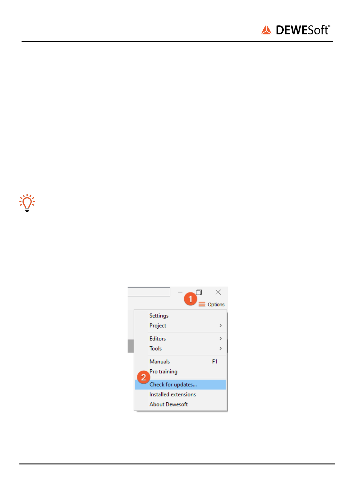
2.1. Software installation
For optimal working, we recommend that you install the latest version of DewesoftX®. If you already
have installed the older version Dewesofti is recommended that you find the newest version on the
website under Support/Downloads/DewesoftX section. You can also check if a newer version is available
in software.
Image 1: Check for update
SIRIUSi-XHS® - V21-2
6/52
SIRIUSi-XHS®
TECHNICAL REFERENCE MANUAL
2.2. Connecting SIRIUSi-XHS®
In this chapter, you can see the basic instructions for connecting SIRIUSi-XHS® devices over 3.0 USB and
RJ-45 ethernet connection. Advanced connections are described in the following chapters.
Important
The XHS device is not supported on the Windows 7.
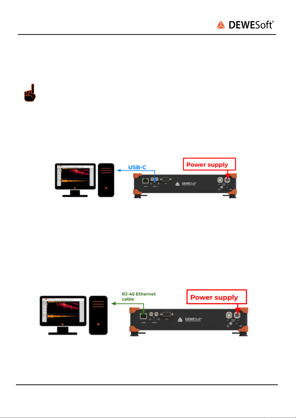
2.2.1. Connection over 3.0. USB
First connect the power supply cable (PS-120-L1B2f) to the PWR IN 2-pin LEMO 1B male connector. Then
connect the usb cable with the USB-C connector to the appropriate connector on the back of the XHS
device. Finally connect the other side of the USB cable with the USB-A connector to the PC. You can find
advanced connections in chapter
Image 2: USB connection
2.2.1.1. Sample rate limitation when connected with USB
When the device is connected via 3.0. USB all 8-channels can run with the 15MHz sample rate.
2.2.2. Connection over EtherNET
First connect the power supply cable (PS-120-L1B2f) to the PWR IN 2-pin LEMO 1B male connector. Then
connect the Ethernet Cable with RJ-45 connector to the appropriate GLAN connector on the back of the
XHS device. Finally connect the other side of the ethernet cable to the LAN port of PC.
Image 3: Connection over Ethernet
SIRIUSi-XHS® - V21-2
7/52

SIRIUSi-XHS®
TECHNICAL REFERENCE MANUAL
2.2.2.1. Sample rate limitation when connected with Ethernet
When connecting the device via Ethernet there is a limitation of sample rate, depending on how many
channels we want to use.
Nr. of channels used in measure
Data Rate / channel
2
15 MS/s
4
5 MS/s
6
1,875 MS/s
8
1 MS/s
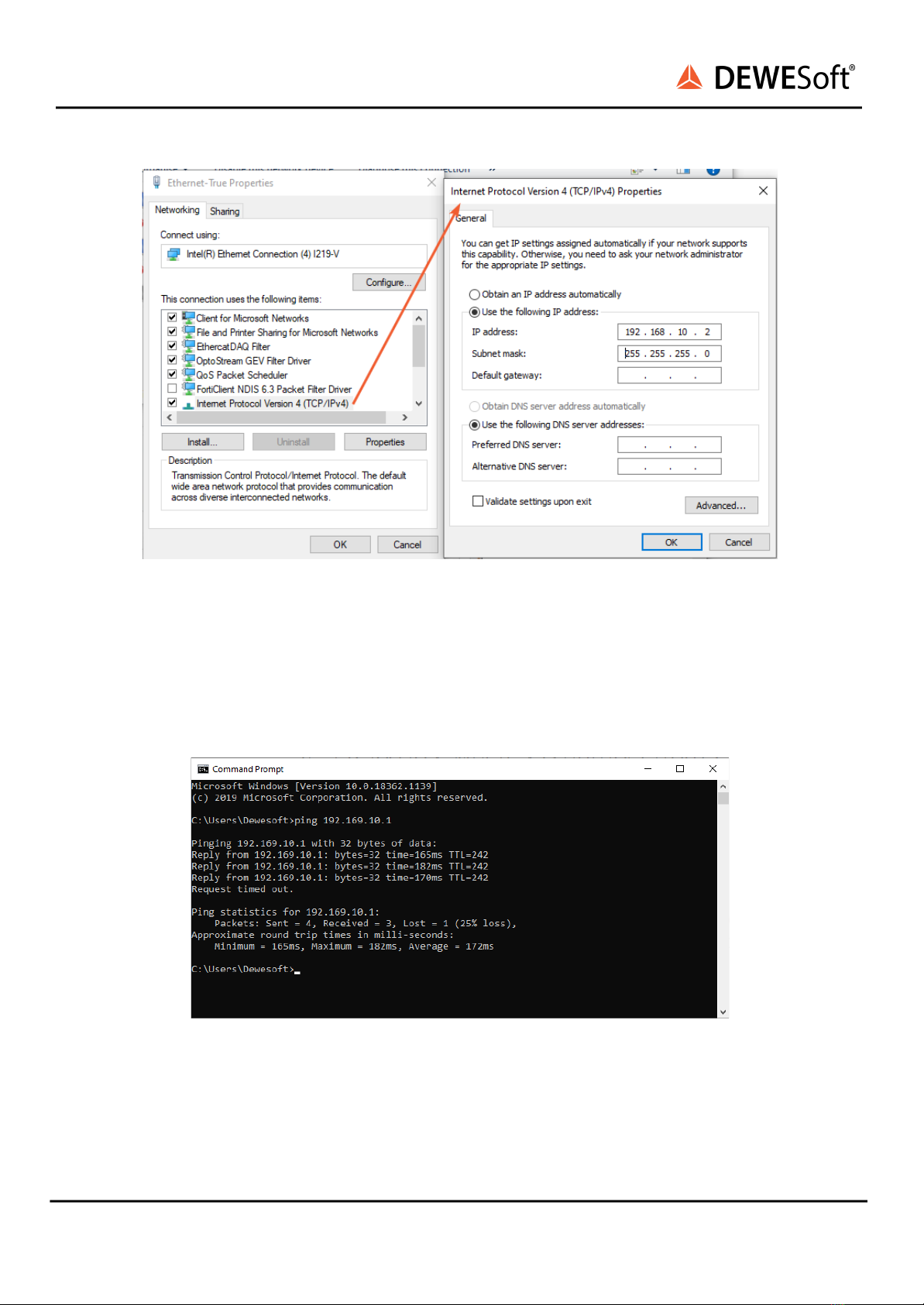
2.2.2.2. Ethernet configuration on the PC
As SIRIUSi-XHS® is a network device with static IP, you need to adjust the Network Card settings when
connecting it via Ethernet. The ethernet port on your SBOX, data logger or PC should be configured in a
way to match the IP address of the SIRIUSi-XHS® device.
Example
SIRIUSi-XHS® has the IP address 192.168.10.1
Your network adapter should be set to:
- IP: 192.168.10.x, where x is number from 2-255
- Subnet mask: 255.255.255.0
SIRIUSi-XHS® - V21-2
8/52
SIRIUSi-XHS®
TECHNICAL REFERENCE MANUAL
Image 4: Setting up IP address
2.2.2.3. Troubleshooting
If DewesoftX® doesn’t detect your devices you should try pinging them via command prompt. In
command prompt write: ping IP replace IP with IP that is set on your device.
The result should be something like this:
Image 5: ping IP in Command Prompt
SIRIUSi-XHS® - V21-2
9/52

SIRIUSi-XHS®
TECHNICAL REFERENCE MANUAL
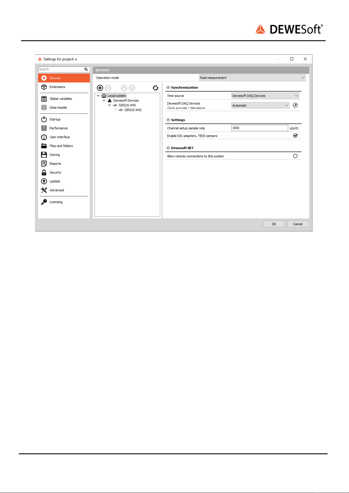
2.2.3. DewesoftX® settings for SIRIUSi-XHS®
The connected device will show up in the DewesoftX® settings. Click on the Options button at the top
right, and then on the Settings item in the pop-up to open the DewesoftX® settings dialogue.
Image 6: DewesoftX® settings
In case the XHS device is connected via USB, the device will automatically be listed under the Dewesoft
devices. When you select the device the properties pane at the right will show the related data e.g. Serial
number, Firmware version, etc.
SIRIUSi-XHS® - V21-2
10/52
SIRIUSi-XHS®
TECHNICAL REFERENCE MANUAL
Image 7: the device shown in Device list
When you connect the SIRIUSi-XHS® device over Ethernet the device is treated as a RT device and
therefore needs to be configured in that way. Adding a new XHS device is done by clicking the plus
button in the device screen. This will show the Add device window where you can find and select a
Real-time controller option. If two SIRIUSi-XHS® devices are used, two different RT devices need to be
added to the device list.
SIRIUSi-XHS® - V21-2
11/52

SIRIUSi-XHS®
TECHNICAL REFERENCE MANUAL
Image 8: Adding RT device
From the 2020.2 Release candidate version the RT-device option is no longer experimental. In
older software versions the Support of RT-devices is still an Experimental feature and it needs to
be enabled under advanced -> Experimental settings.
SIRIUSi-XHS® - V21-2
12/52

SIRIUSi-XHS®
TECHNICAL REFERENCE MANUAL
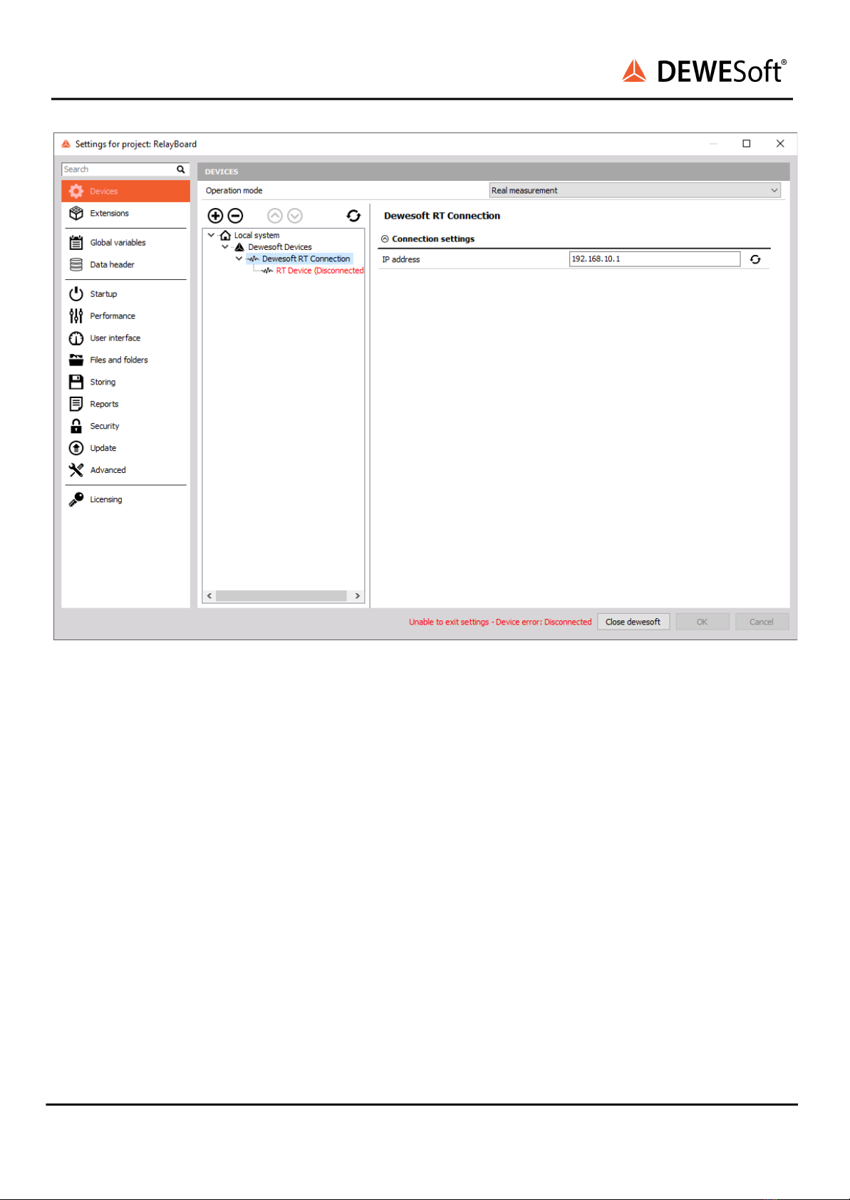
After that you will see a new SIRIUSi-XHS® or Dewesoft RT connection in the device tree.
Image 9: RT device Connection
If the text by the device is disconnected, you should click on the device (Dewesoft RT Connection) , set
the correct IP and refresh.
SIRIUSi-XHS® - V21-2
13/52
SIRIUSi-XHS®
TECHNICAL REFERENCE MANUAL
Image 10: Setting IP
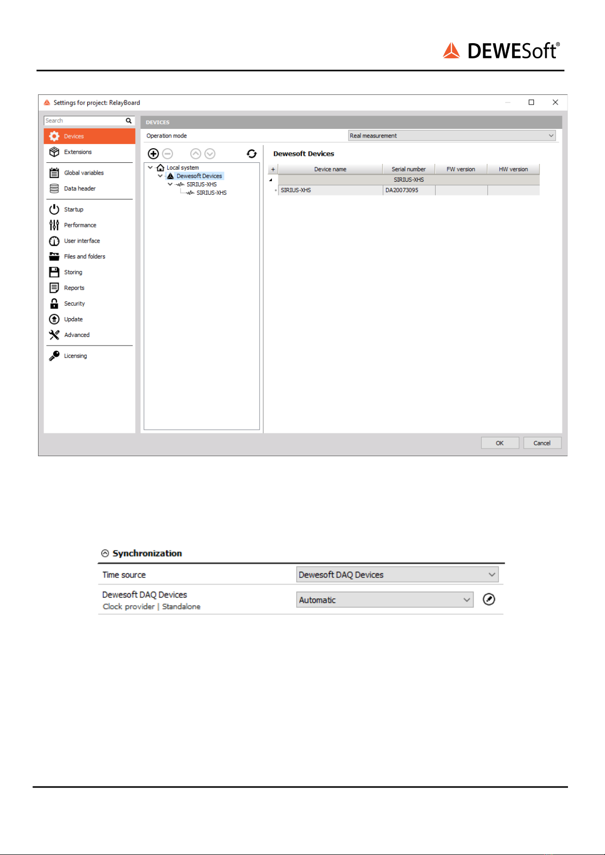
If everything is set correctly both devices should be detected as SiriusXHS devices.
SIRIUSi-XHS® - V21-2
14/52
SIRIUSi-XHS®
TECHNICAL REFERENCE MANUAL
Image 11: Devices overview
Before measurement you need to set synchronization. This is done by selecting Local system and
selecting time source. When you have only one device you can select the Dewesoft DAQ devices and
Automatic/Standalone mode.
Image 12: Setting synchronization
When you have multiple XHS devices you can use External (Clock provider) as PTP (Precision Time
Protocol) and Dewesoft DAQ Devices (Clock slave) as PTP.
SIRIUSi-XHS® - V21-2
15/52
SIRIUSi-XHS®
TECHNICAL REFERENCE MANUAL
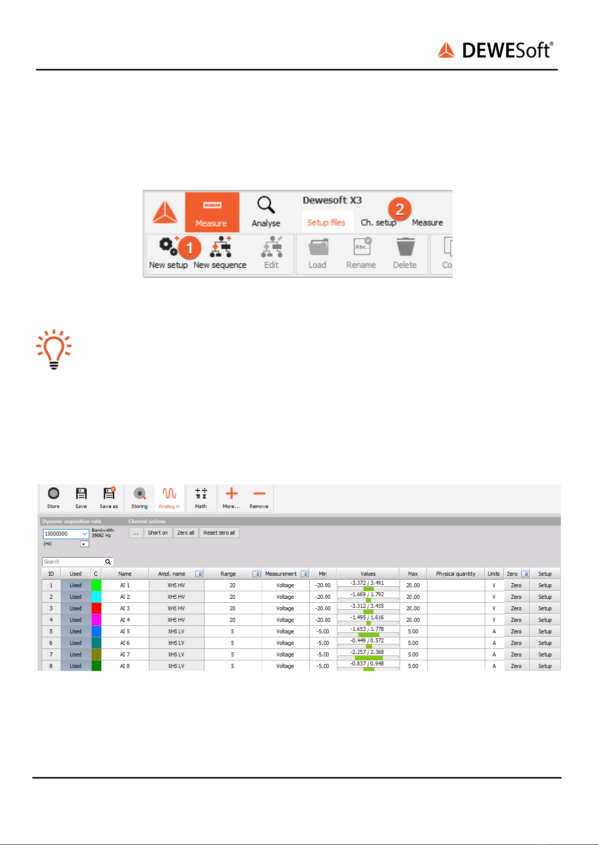
2.2.4. Channel Setup SIRIUSi-XHS®
When Dewesoft has started up, you will be in the Measure mode and see the Setup files list or you can
create a New setup ❶. Click on Ch. setup (on the right of Setup files) to switch to the Channel setup
mode ❷. In the channel setup you can see a preview of the connected devices on the upper left side.
Image 13: Setup files
Hint
When you click on a connector in the image the corresponding channel in the Channel setup
grid will automatically be selected. This also works the other way around: when you select a
channel (or multiple channels) in the setup grid, the corresponding connectors in the image
will be highlighted.
The sampling rate will be set for all connected SIRIUSi-XHS® units: of course only up to the max.
sampling rate of the individual units.
In channel setup mode you can set the wanted sample rate, range etc. and select channels you want to
measure.
Image 14: Channel setup
SIRIUSi-XHS® - V21-2
16/52

SIRIUSi-XHS®
TECHNICAL REFERENCE MANUAL
2.3. Simple Measurement
This chapter describes measurement basics, how to configure SIRIUSi-XHS® and gives some details on
the measurement setup.
2.3.1. Help - Manual
Note that this document is just a quick start guide. For detailed information about Dewesoft consult the
Manual. To open the manual press the F1 button or click on the Options button ❶and then select
Manual from the pop-up menu ❷.
Image 15: Help - Manual
When DewesoftX® has started up, you will be in Measure mode and see the Setup files list. Click on Ch.
setup (on the right of Setup files) to switch to the Channel setup mode.
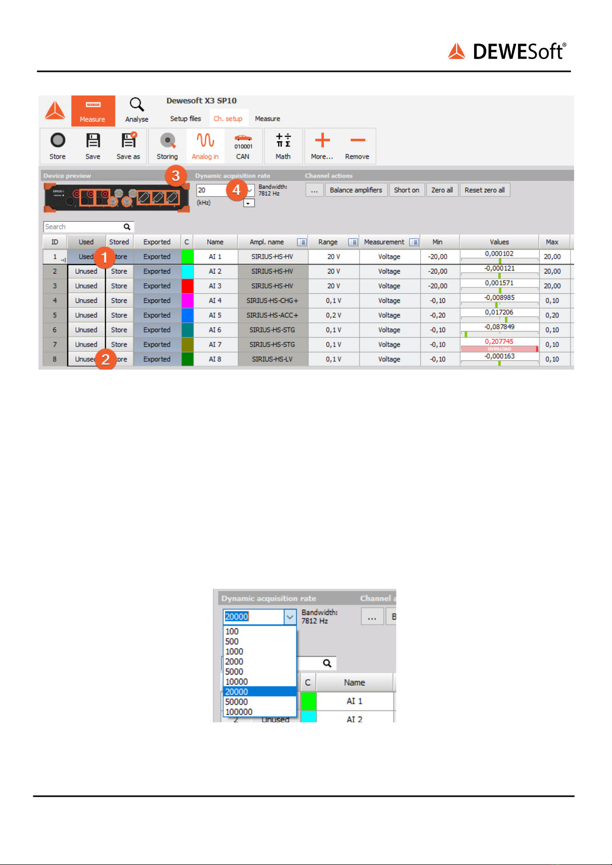
2.3.2. Analogue channel setup
In the analog channel setup screen you can see all channels of your connected SIRIUS systems. Per
default only the first channel will be set to Used. Unused channels will not show up in measure mode
and can thus not be used for display, calculations or storing: thus, we will also set the other channels to
the used. You can left-click on the Used column of channel 2 ❶, hold the mouse button and move the
mouse down to channel 6 ❷: then release the mouse button and all channels will be selected – this is
shown by the black rectangle around the buttons. Then you can click into the selected region to toggle
Used/Unused for all channels at once. The selected channels will also be highlighted in the small
preview image of the device ❸.
When you press the Setup button of a channel (the column at the right edge of the channel table – not
shown in this screen-shot), you can change all the settings of the channel amplifier. You can also
change the sample rate of SIRIUS ❹.
SIRIUSi-XHS® - V21-2
17/52
SIRIUSi-XHS®
TECHNICAL REFERENCE MANUAL
Image 16: Channel setup screen
2.3.3. Sample rate
One of the most important settings is the sample rate. The sample rate defines how many data points
SIRIUS will transfer to the Dewesoft. Higher sample rate also means that more data needs to be
transferred via USB to your computer.
The sampling speed mainly depends on your application. To display your signal in a time domain with a
good time resolution, you should sample 10 to 20 times faster than the frequency of the signal that you
want to measure, e.g. 1 kS/s for a 50 Hz sine-wave. If you have a lot of high frequency components, it may
be necessary to sample 100 times faster, e.g. 5 kS/s for the 50 Hz sine-wave, or even more. If you display
only the frequency domain (FFT analysis), a 2.5 times faster sampling would be sufficient (125 S/s for the
50 Hz sine-wave). The higher the sampling rate, the better the time resolution. But also the file size will
increase.
Image 17: Sample rate
SIRIUSi-XHS® - V21-2
18/52
SIRIUSi-XHS®
TECHNICAL REFERENCE MANUAL
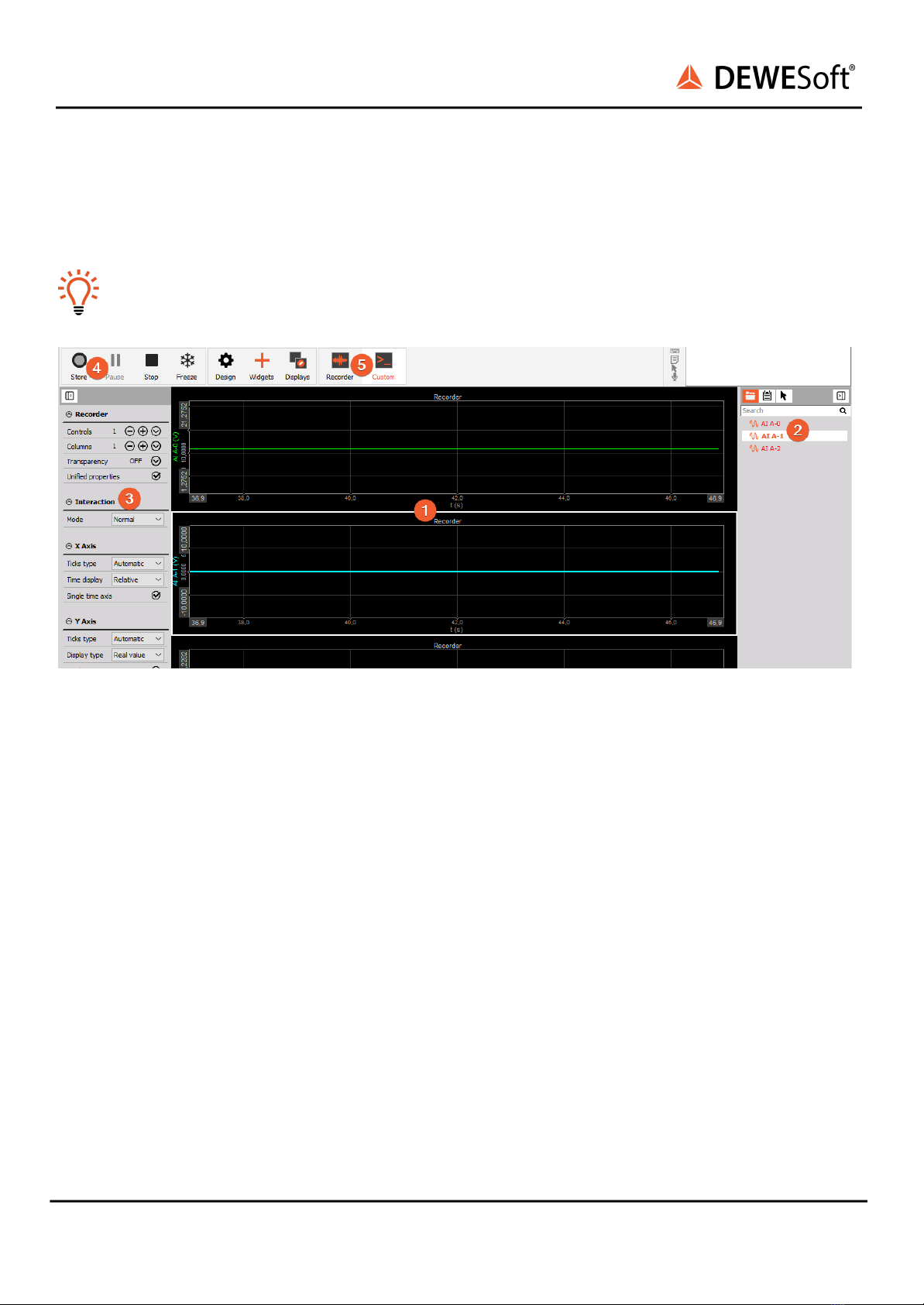
2.3.4. Measurement Mode
A click on Measure (at the right side of Ch. setup in Illustration 11) will take you to the Recorder screen
measure mode where you can already see live data.
Hint
When switching to Measure mode the data will not be stored automatically.
Image 18: Measure mode
In measure mode you can have several measurement screens ❺. Dewesoft will create 2 default displays:
Recorder and Custom but you can also create new displays or change the widgets on existing displays
as you like.
The most important sections of the Measure mode are highlighted in screen-shot Illustration “Measure
mode”:
❶shows the live measurement data in different widgets which are depending on the selected
measurement screen. In this case we see a simple recorder widget where data is presented in time
domain. You can use the channel-selector list ❷to assign measurement channels to the widgets. Each
widget has different settings, ❸shows the settings of the currently selected recorder widget.
To start storing the data, press the Store button ❹. When you are done with recording, press the Stop
button.
Now Dewesoft has created a data file with all the data that you have seen during the recording session.
You can now click the Analyse button (on the left-top of the screen to the right of the Measure button)
to go to Analyse mode.
2.3.5. Analyse Mode
When you have just stopped a measurement, DewesoftX® will automatically open the last recorded
data file in Review mode, so that you can start the analysis right away.
SIRIUSi-XHS® - V21-2
19/52

SIRIUSi-XHS®
TECHNICAL REFERENCE MANUAL
Image 19: Analyse mode
The Review mode is much like the measurement mode. You will see the same measurement screens,
the channel-selector list and the properties of the currently selected instrument.
Differences are:
(1) you have additional tool-buttons
(2) there is a Signal overview window which will show you the whole data of one selected channel of the
data file
Now you can use the cursors to analyse your data, zoom in and out of the data, click Offline math to add
computations based on your data, etc. You can also change the design of your measurement screens,
print reports based on your data and export the data to other file formats for further analysis.
2.4. Advanced configuration
Note, that the Dewesoft launcher has already done the hardware setup for you – you can check this in
the Settings dialogue. Click the Option button ❶– and then click the Settings menu item ❷.
SIRIUSi-XHS® - V21-2
20/52
Table of contents


