DEWESOFT DS-GPS-CLOCK Product manual

DS-GPS-CLOCK
TECHNICAL REFERENCE MANUAL
DS-GPS-CLOCK V20-2
1

DS-GPS-CLOCK
TECHNICAL REFERENCE MANUAL
1. Table of contents
1. Table of contents 2
2. About this document 4
2.1. Legend 4
3. Specifications 5
3.1. Shock & Vibration 6
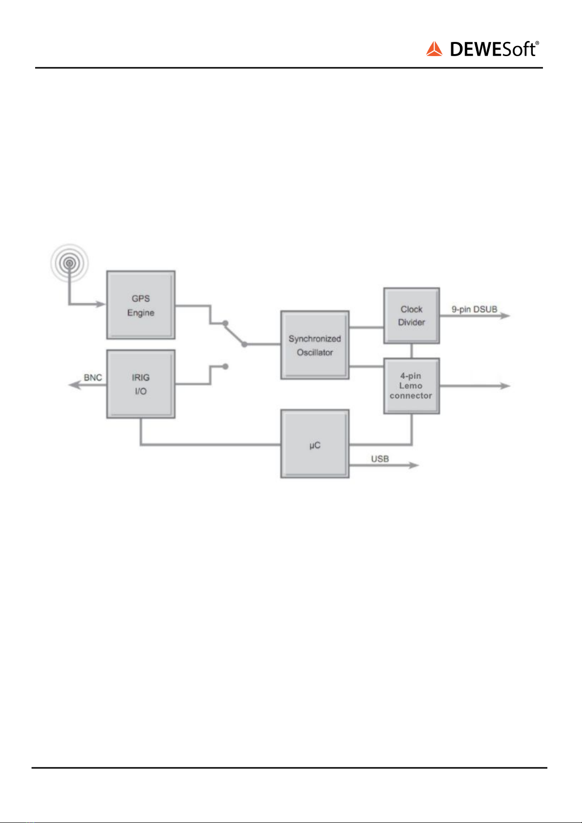
4. Device overview 7
4.1. GPS based operation 8
4.2. IRIG based operation 8
4.3. LED Description 8
4.3.1. Power 8
4.3.2. Status 9
4.4. Mounting the aerial 9
4.5. Warm-Up time 9
4.6. Scope of supply 10
4.7. Connection 11
4.7.1. Front Connectors 11
4.7.1.1. LEDs 11
4.7.1.2 Aerial connector 11
4.7.1.3 IRIG connector 12
4.7.2. Rear Connectors 12
4.7.2.1. Multi I/O Connector 13
4.7.2.2. Mini USB connector 14
4.7.2.3. SYNC connector 14
4.8. Installation 15
4.9. Connecting the DS-GPS-CLOCK to the DAQ-System 15
4.9.1. Synchronization to system with Clock and Trigger 15
4.10. Configuration of DewesoftX® for the DS-GPS-CLOCK 15
4.10.1. Update rate 16
4.10.2. Maps directories 16
4.10.3. Timing settings 16
4.10.3.1. Input settings 18
4.11. Channel setup 19
4.12. Measurement setup 20
4.13. Time code restore 20
5. Warranty information 23
5.1. Calibration 23
5.2. Support 23
5.3. Service/repair 23
5.4. Restricted Rights 24
DS-GPS-CLOCK V20-2 2/28

DS-GPS-CLOCK
TECHNICAL REFERENCE MANUAL
5.5. Printing History 24
5.6. Copyright 24
5.7. Trademarks 24
6. Safety instructions 24
6.1. Safety symbols in the manual 24
6.2. General Safety Instructions 24
6.2.1. Environmental Considerations 25
6.2.2. Product End-of-Life Handling 25
6.2.3. System and Components Recycling 25
6.2.4. General safety and hazard warnings for all Dewesoft systems 25
7. Version History 28
DS-GPS-CLOCK V20-2 3/28

DS-GPS-CLOCK
TECHNICAL REFERENCE MANUAL
2. About this document
2.1. Legend
The following symbols and formats will be used throughout the document.
Important
It gives you important information about the subject.
Please read carefully!
Hint
It gives you a hint or provides additional information about a subject.
Example
Gives you an example of a specific subject.
DS-GPS-CLOCK V20-2 4/28

DS-GPS-CLOCK
TECHNICAL REFERENCE MANUAL
3. Specifications
DS-GPS-CLOCK V20-2 5/28
IRIG Input Specifications
Supported codes
IRIG code A or B / AM or DC
Compatibility (AM code)
0.5 Vpp to 10 Vpp
Ratio (AM)
3:1 ±10 %
Compatibility (DC code)
DC Level Shift TTL / CMOS compatible
Impedance
20 kΩ
Isolation
150 VDC
Trigger accuracy
1 µsec
IRIG output specifications
Supported codes
IRIG code B, DC
Isolation
None
Accuracy
< 1 µsec (delay to GPS PPS)
GPS specifications
General
12 channel, L1 frequency receiver
PPS accuracy
100 ns
Refresh rate
1 Hz
Position accuracy
Horizontal CEP
Autonomous
3.0 m
Differential
1.0 m
Trigger accuracy
1 µsec
System specifications
Clock accuracy locked
without drift
Clock accuracy unlocked
< 10 ppm
Input
SMA for GPS antenna, BNC for IRIG I/O

DS-GPS-CLOCK
TECHNICAL REFERENCE MANUAL
3.1. Shock & Vibration
DS-GPS-CLOCK V20-2 6/28
Output: Trigger:
Clock and Trigger for DAQ-systems on DB9 connector
PPS (pulse per second), rising edge on time, 75 msec high
time, TTL level compatible 10 Hz to 10 MHz, rising edge
synchronized, 50 % duty cycle, TTL level compatible.
Power supply
USB powered, max. current 500 mA
Environmental specifications
Operation temperature
-5 °C to +70 °C
Storage temperature
-20 °C to +85 °C
Humidity
10 % to 80 %; non condensing
Dimensions (W x D x H)
133 x 104 x 43 mm (5.23 x 4.1 x 1.7 in.)
Weight
approx. 330 g (0.72 lb)
Vibration Tests
Shock Test
European Standard
EN 600068-2-6
EN 60721-3-2 Class 2M2
EN 60068-2-27
Shape
Sine
Random
Half-sine
Frequency
0 Hz to 150 Hz
10 - 200 Hz
Power spectral density
1 m/s² / Hz from 10 – 200 Hz
Acceleration amplitude
15 g
Duration
30 Minutes per axis
30 Minutes per axis
11 ms
Test in 3 axis, 3 shocks in each axis and direction

DS-GPS-CLOCK
TECHNICAL REFERENCE MANUAL
4. Device overview
The DS-GPS-CLOCK is a synchronized time base generator capable of using either GPS or IRIG as a time
source. This allows completely synchronized data acquisition of multiple systems whether they are
mobile or stationary. Additionally, the DS-GPS-CLOCK can also be used as an IRIG time code generator
(output IRIG B/DC) synchronized to the GPS time.
The diagram below outlines the basic functionality of the DS-GPS-CLOCK:
Image 1: Block Diagram
DS-GPS-CLOCK V20-2 7/28

DS-GPS-CLOCK
TECHNICAL REFERENCE MANUAL
4.1. GPS based operation
The base of any GPS receiver is precise time measurement. In addition to the position information a
precise PPS (pulse per second) is generated by the GPS engine. This pulse is used to synchronize a 40
MHz oscillator with software PLL (phase locked loop). The result is an ultra-stable 40 MHz clock source
which is completely free of drift over time.
Out of this 40 MHz base clock, the programmable clock divider generates the clock frequency for the
standard data acquisition system which is being output on the 9-pin DSUB connector or 4-pin Lemo
connector.
4.2. IRIG based operation
The IRIG signal contains the binary-coded time (year, day of year, hours, minutes, seconds, fractions of a
second) modulated on a sine wave carrier. This signal is decoded to the PPS and the drift-free 40 MHz
clock.
The following IRIG time codes are supported:
●IRIG-A (10 Hz)
●IRIG-B (1 Hz)
4.3. LED Description
4.3.1. Power
The power LED is solid green when the DS-GPS-CLOCK is in normal operation.
Image 2: LED lights
DS-GPS-CLOCK V20-2 8/28

DS-GPS-CLOCK
TECHNICAL REFERENCE MANUAL
4.3.2. Status
The status LED indicates the current status of the device:
4.4. Mounting the aerial
The aerial supplied with the DS-GPS-CLOCK is designed to be mounted magnetically on any metallic
surface. The cable length is 5 m.
Please contact your sales manager if your application requires a different aerial.
4.5. Warm-Up time
When the DS-GPS-CLOCK is used as a GPS based time code generator for the first time, has been
moved more than 200 km, or not used for 10 hours (since last usage), it is recommended to perform a
‘cold start’. To get the best performance from your GPS in the future, perform this cold start in an open
place with a good all round view to the sky. Allow the GPS to map the satellites for at least 20 to 30
minutes. The GPS builds up the ‘Ephemeris’ data on each satellite which is stored in a non-volatile
memory so that future satellite tracking is swift and stable. Once the GPS has carried out a successful
cold start, future satellite lock from power up will take between 15 seconds and 1 minute. Before going to
test in a shady environment with tall objects or near to trees, allow the GPS to settle in an open space for
5 to 10 minutes.
DS-GPS-CLOCK V20-2 9/28
At normal operation - when DS-GPS-CLOCK is
locked to the selected time source - it shortly
blinks once a second.
Image 3: LED: Normal Operation
When the time source signal is missing (neither
GPS or IRIG time code signal), the device
automatically goes to flying-wheel operation. This
is indicated by inverted blinking.
Image 4: LED: Missing Signal

DS-GPS-CLOCK
TECHNICAL REFERENCE MANUAL
4.6. Scope of supply
When ordering the DS-GPS-CLOCK the following supply is also included in the package:
●0.5m 4-pin sync cable, for the synchronization of the system (LEMO SYNC-CBL
FGG00050.0500N2 2xFGG.00.304.CLAD35ZN 0,5m)
●USB-mini cable for connecting the device to the SBOX or PC (CABLE-USBAmini-USBBS-1.8m)
●CABLE-GLONASS-RG174-ANTENNA-5m (GLONASS,5M RG174 2J7501MP ANTENA)
4.7. Connection
4.7.1. Front Connectors
Image 5: Front connectors
4.7.1.1. LEDs
See chapter LED Description
DS-GPS-CLOCK V20-2 10/28

DS-GPS-CLOCK
TECHNICAL REFERENCE MANUAL
4.7.1.2 Aerial connector
4.7.1.3 IRIG connector
DS-GPS-CLOCK V20-2 11/28
Image 6: SMA connector
Pin
Description
1
Hot
2
shield
Image 7 : BNC connector
Pin
Description
1
out
2
GND

DS-GPS-CLOCK
TECHNICAL REFERENCE MANUAL
4.7.2. Rear Connectors
Image 8: Rear Connectors
DS-GPS-CLOCK V20-2 12/28

DS-GPS-CLOCK
TECHNICAL REFERENCE MANUAL
4.7.2.1. Multi I/O Connector
Multi I/O Cable
Image 10: MULTI I/O cable
DS-GPS-CLOCK V20-2 13/28
Image 9: DSUB-9 male connector
Pin
Name
Description
1
n.c.
Not Connected
2
n.c.
Not Connected
3
CLK OUT
Scan clock output
4
n.c.
Not Connected
5
n.c.
Not Connected
6
PPS
Pulse Per Second
7
n.c.
Not Connected
8
DGND
Ground
9
n.c.
Not Connected

DS-GPS-CLOCK
TECHNICAL REFERENCE MANUAL
4.7.2.2. SYNC connector
Interface connector: EEG.00.304.CLL
Mating connector: FGG.00.304.CLAD27Z
DS-GPS-CLOCK V20-2 14/28
Image 11: Sync connector: pin-out (4-pin LEMO female)
Pin
Name
Description
1
CLK
Clock
2
Trigg
Trigger
3
GPS-PPS
GPS - PPS
4
DGND
Digital Ground

DS-GPS-CLOCK
TECHNICAL REFERENCE MANUAL
4.8. Installation
The hardware drivers for the DS-GPS-CLOCK are automatically installed together with DewesoftX®.
There is no additional SW needed. You can start the software in the Windows start menu or use the icon
created on your desktop. For more information about the DewesoftX® installation please refer to the
DewesoftX® Software User's Manual.
4.9. Connecting the DS-GPS-CLOCK to the DAQ-System
4.9.1. Synchronization to system with Clock and Trigger
To synchronize standard data acquisition systems a start trigger and the possibility of external clocking
is required. This input needs to be connected to the output of the DS-GPS-CLOCK sync signals of the
9-pin DSUB female (signal Scan Clock Output and PPS).
4.10. Configuration of DewesoftX® for the DS-GPS-CLOCK
When the DS-GPS-CLOCK is connected it will be automatically recognized in DewesoftX® Device
settings menu:
Image 12: DewesoftX® device settings
DS-GPS-CLOCK V20-2 15/28

DS-GPS-CLOCK
TECHNICAL REFERENCE MANUAL
4.10.1. Update rate
The update rate is fixed at 1 Hz.
4.10.2. Maps directories
Select the directories, where you stored your maps. You can copy your maps into this directory, add
individual directories or remove unused directories from the box. Convert the maps to .jpg or .bmp
format before selecting them.
4.10.3. Timing settings
When you want to use the DS-GPS-CLOCK as a high precision timing device for synchronized data
acquisition, you need set the Time source as External.
a.) IRIG input
Image 13: IRIG as external source
DS-GPS-CLOCK V20-2 16/28

DS-GPS-CLOCK
TECHNICAL REFERENCE MANUAL
b.) GPS input
Image 14: GPS as external source
DS-GPS-CLOCK V20-2 17/28

DS-GPS-CLOCK
TECHNICAL REFERENCE MANUAL
4.10.3.1. Input settings
Time source
Here you can select which input signal (GPS or IRIG) is used for the time source.
Code type
If IRIG mode is selected as a time source, this drop-down menu defines the used code type (IRIG-A,
IRIG-B or IRIG-G).
Modulation
This selects the modulation type (AC or DC) of the IRIG input signal.
Output settings
The check-box “IRIG Out” enables the output of the internally generated IRIG signal on the BNC
connector of the DSCLOCK.
Please note that only IRIG-B with DC modulation is supported as output signal.
Set do default Button
This button defines the current input- and output settings as power on default settings. This way the
DS-GPS-CLOCK will always start up with the predefined settings.
DS-GPS-CLOCK V20-2 18/28

DS-GPS-CLOCK
TECHNICAL REFERENCE MANUAL
4.11. Channel setup
The screenshot below shows the channel setup screen of the DS-GPS-CLOCK when it was selected as a
GPS device. In the column ON/OFF you can select the channels for storing during the measurement.
The default channel names are displayed in the column NAME. You can change them with a double
click on it. Beside the channel names the actual value is displayed.
Image 15: Channel Setup
●Longitude component of position in degrees, minutes and fraction of minutes
●Latitude component of position in degrees, minutes and fraction of minutes
●Z: Altitude in meters above sea level
●Velocity: Speed over ground (vector of all 3 dimensions)
●Direction: True track over ground
●Distance: Integration of speed for getting the displacement (Only speed levels above 0.5 km/h
are used to calculate the distance)
●Used sat.: Numbers of satellites used for calculation of position and speed
●Current sec: Seconds since midnight (UTC)
●GPS fix quality: To recognize in which mode the receiver is (Standalone, DGPS, RTK)
●NMEA: The raw NMEA string from the GPS receiver
The circle on the right gives an overview of the satellites in view of the GPS receiver and which of them
are used from the receiver. The colour of the shown satellites indicates the signal strength of them.
From grey to dark green which is the strongest signal. Satellites shown in the centre of the circle are
directly above the GPS-aerial. Satellites shown at the border of the circle are near the horizon.
The field <PPS sync> and <Not fixed> change their colour from grey to green depending if the
appropriate feature is available at the moment (green means available).
DS-GPS-CLOCK V20-2 19/28

DS-GPS-CLOCK
TECHNICAL REFERENCE MANUAL
The PPS sync is used for hardware synchronisation to analogue channels. This will eliminate the time
shift caused due the calculation time of the GPS receiver and of the data transfer time of the USB
interface.
The button “NMEA log” shows/hides the raw NMEA data stream from the GPS receiver.
4.12. Measurement setup
When the DS-GPS-CLOCK is used as a timing device and you switch to the measurement screen you
will see the actual time from the DS-GPS-CLOCK shown in the top right corner of the screen. A green
clock next to this time indicates that the DS-GPS-CLOCK is locked to the GPS or IRIG time whereas a red
clock with additional Sync Lost warning indicates that the DS-GPS-CLOCK does not have any real input.
Image 16: sync OK
Image 17: sync lost
By default the local time is stored inside the data file, but if the measurement results from multiple
systems located in different time zones should be analysed it is recommended to set to UTC or GPS time
(Local time in settings). This can be done in the Global settings of DewesoftX® (Settings Global settings
Displays). Doing so, the data from all data acquisition systems are containing the same absolute time
stamp.
Image 18: Global Time Settings
DS-GPS-CLOCK V20-2 20/28
Table of contents
Popular Inverter manuals by other brands

Peak Performance
Peak Performance PKC0BM Owner's manual and warranty information

Toshiba
Toshiba ACE-tronics G9 ASD quick start guide

Mitsubishi Electric
Mitsubishi Electric 800 Series Instruction Manual (Function

Epever
Epever Tracer1305EPLI manual

POW
POW Metron4 M4/SOL-SYS Easy Install Guide

WEICHAI
WEICHAI WPG13.5 Operation manual