manuals.online logo
Brands
  1. Home
  2. •
  3. Brands
  4. •
  5. DFI
  6. •
  7. Motherboard
  8. •
  9. DFI PR810-C622 User manual

DFI PR810-C622 User manual

Other DFI Motherboard manuals

DFI HM101-QM87 User manual

DFI

DFI HM101-QM87 User manual

DFI AM75-EC User manual

DFI

DFI AM75-EC User manual

DFI GHF51 User manual

DFI

DFI GHF51 User manual

DFI PT332-DRM User manual

DFI

DFI PT332-DRM User manual

DFI 686IPK User manual

DFI

DFI 686IPK User manual

DFI SR330-N User manual

DFI

DFI SR330-N User manual

DFI EL630-NR User manual

DFI

DFI EL630-NR User manual

DFI Infinity NF series User manual

DFI

DFI Infinity NF series User manual

DFI NB72-SC User manual

DFI

DFI NB72-SC User manual

DFI PR610-C621 User manual

DFI

DFI PR610-C621 User manual

DFI NS35-TC User manual

DFI

DFI NS35-TC User manual

DFI NB30-EC User manual

DFI

DFI NB30-EC User manual

DFI 915G-TMGF User manual

DFI

DFI 915G-TMGF User manual

DFI G4S306-C User manual

DFI

DFI G4S306-C User manual

DFI LanParty LT P35 User manual

DFI

DFI LanParty LT P35 User manual

DFI CS620-H310 User manual

DFI

DFI CS620-H310 User manual

DFI G7V600-B User manual

DFI

DFI G7V600-B User manual

DFI CS62-TC User manual

DFI

DFI CS62-TC User manual

DFI CR100-CRM User manual

DFI

DFI CR100-CRM User manual

DFI AM75-TC User manual

DFI

DFI AM75-TC User manual

DFI LanParty UT X38 Series User manual

DFI

DFI LanParty UT X38 Series User manual

DFI SB331-IPM User manual

DFI

DFI SB331-IPM User manual

DFI CS632-C246 User manual

DFI

DFI CS632-C246 User manual

DFI AD73 Pro User manual

DFI

DFI AD73 Pro User manual

Popular Motherboard manuals by other brands

Gigabyte MNJ190I-FH user manual

Gigabyte

Gigabyte MNJ190I-FH user manual

Biostar HI-FI-Z87X-3D Setup manual

Biostar

Biostar HI-FI-Z87X-3D Setup manual

Atmel SAM9753PIA-DK user guide

Atmel

Atmel SAM9753PIA-DK user guide

Coapt GEN2 Handbook

Coapt

Coapt GEN2 Handbook

Supero SUPER P4DL6 user manual

Supero

Supero SUPER P4DL6 user manual

Cypress CY3210-PSoCEVAL1 quick start guide

Cypress

Cypress CY3210-PSoCEVAL1 quick start guide

ASROCK B660M-HDV manual

ASROCK

ASROCK B660M-HDV manual

Fujitsu D2831 Short description

Fujitsu

Fujitsu D2831 Short description

Industrial Computers ADE-6050 user manual

Industrial Computers

Industrial Computers ADE-6050 user manual

Asus TUF Z270 MARK 2 manual

Asus

Asus TUF Z270 MARK 2 manual

ASROCK H61 Pro BTC user manual

ASROCK

ASROCK H61 Pro BTC user manual

Norco POS-7893 user manual

Norco

Norco POS-7893 user manual

Intel DG965MS specification

Intel

Intel DG965MS specification

Asus B85M-VIEW PAKER user manual

Asus

Asus B85M-VIEW PAKER user manual

Asus P5G41T-M LX V2 user manual

Asus

Asus P5G41T-M LX V2 user manual

Gigabyte GA-K8VT800-RH user manual

Gigabyte

Gigabyte GA-K8VT800-RH user manual

Gigabyte Z790M AORUS ELITE user manual

Gigabyte

Gigabyte Z790M AORUS ELITE user manual

Semtech SC120 user guide

Semtech

Semtech SC120 user guide

manuals.online logo
manuals.online logoBrands
  • About & Mission
  • Contact us
  • Privacy Policy
  • Terms and Conditions

Copyright 2025 Manuals.Online. All Rights Reserved.

PR810-C622
A-614-M-2040
ATX Industrial Motherboard
User’s Manual
2User's Manual | PR810-C622
Copyright
This publication contains information that is protected by copyright. No part of it may be repro-
duced in any form or by any means or used to make any transformation/adaptation without the
prior written permission from the copyright holders.
This publication is provided for informational purposes only. The manufacturer makes no
representations or warranties with respect to the contents or use of this manual and specifi-
cally disclaims any express or implied warranties of merchantability or fitness for any particular
purpose. The user will assume the entire risk of the use or the results of the use of this docu-
ment. Further, the manufacturer reserves the right to revise this publication and make changes
to its contents at any time, without obligation to notify any person or entity of such revisions or
changes.
Changes after the publication’s first release will be based on the product’s revision. The website
will always provide the most updated information.
© 2020. All Rights Reserved.
Trademarks
Product names or trademarks appearing in this manual are for identification purpose only and
are the properties of the respective owners.
FCC and DOC Statement on Class B
This equipment has been tested and found to comply with the limits for a Class B digital
device, pursuant to Part 15 of the FCC rules. These limits are designed to provide reason-
able protection against harmful interference when the equipment is operated in a residential
installation. This equipment generates, uses and can radiate radio frequency energy and, if not
installed and used in accordance with the instruction manual, may cause harmful interference
to radio communications. However, there is no guarantee that interference will not occur in a
particular installation. If this equipment does cause harmful interference to radio or television
reception, which can be determined by turning the equipment off and on, the user is encour-
aged to try to correct the interference by one or more of the following measures:
• Reorient or relocate the receiving antenna.
• Increase the separation between the equipment and the receiver.
• Connect the equipment into an outlet on a circuit different from that to which the re-
ceiver is connected.
• Consult the dealer or an experienced radio TV technician for help.
Notice:
1. The changes or modifications not expressly approved by the party responsible for com-
pliance could void the user’s authority to operate the equipment.
2. Shielded interface cables must be used in order to comply with the emission limits.
3User's Manual | PR810-C622
Table of Contents
Chapter 1 - Introduction................................................................................................................6
Specifications ......................................................................................................................... 6
Features .................................................................................................................................. 8
Block Diagram ........................................................................................................................9
Chapter 2 - Hardware Installation..............................................................................................10
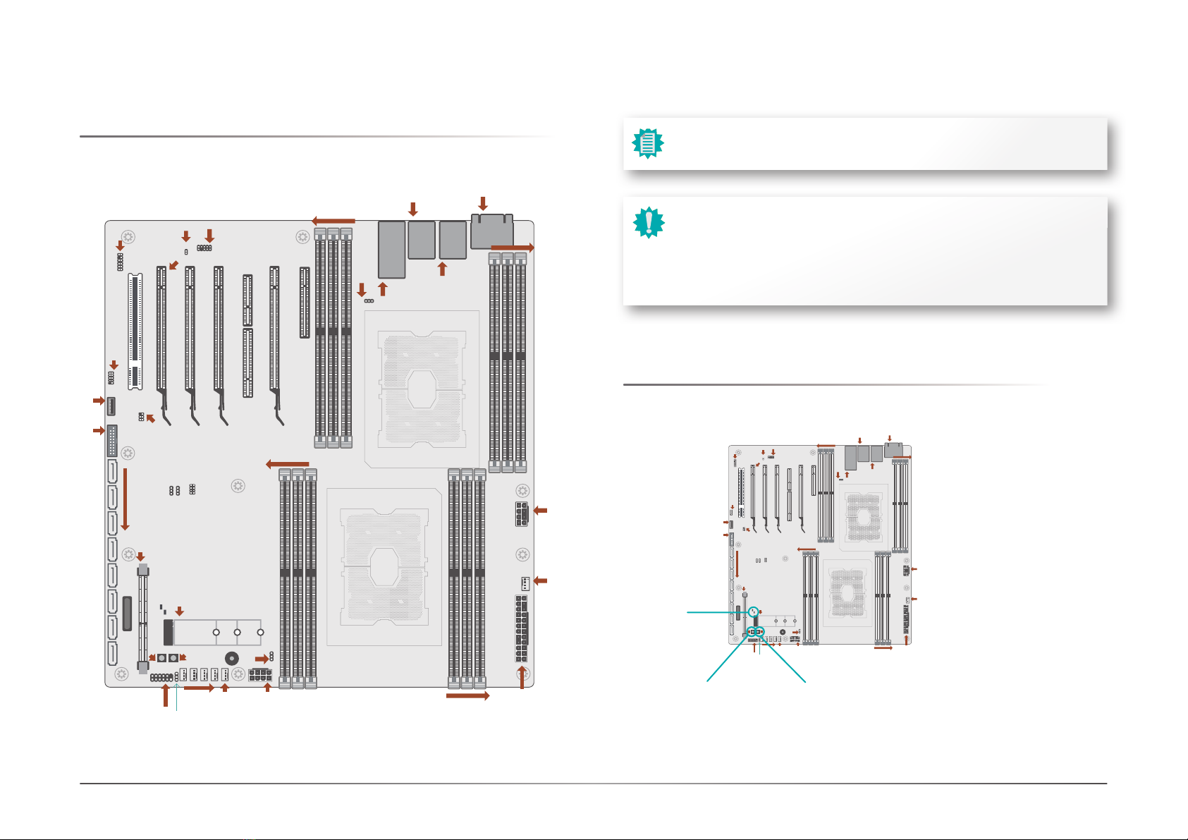
Board Layout.........................................................................................................................10
LED and Switch ....................................................................................................................10
System Memory ...................................................................................................................11
Installing the DIMM Module .........................................................................................11
Removing the DIMM Module........................................................................................12
CPU........................................................................................................................................13
Installing the CPU, Fan and Heat Sink.........................................................................13
Jumper Settings ...................................................................................................................15
Clear CMOS....................................................................................................................15
ME Firmware Update.....................................................................................................15
FLASH SECURITY OVERRIDE........................................................................................16
Rear I/O Ports.......................................................................................................................17
Graphics Display............................................................................................................17
COM (Serial) ports.........................................................................................................18
RJ45 LAN Ports .............................................................................................................18
USB Ports .......................................................................................................................19
Internal I/O Connectors .......................................................................................................20
SATA (Serial ATA) ..........................................................................................................20
Front Audio.....................................................................................................................20
Cooling Fan Connectors................................................................................................21
Power Connector...........................................................................................................21
Chassis Intrusion...........................................................................................................22
Front Panel.....................................................................................................................22
Expansion Slots .............................................................................................................23
Installing the M.2 Module .............................................................................................23
LPC .................................................................................................................................24
Battery ............................................................................................................................25
SMBus ............................................................................................................................25
JTAG PLD Programming...............................................................................................26
Chapter 3 - BIOS Setup...............................................................................................................27
Overview ...............................................................................................................................27
Main.......................................................................................................................................28
Advanced .............................................................................................................................28
ACPI Configuration........................................................................................................29
CPU Configuration.........................................................................................................30
Video Configuration.......................................................................................................30
SATA Configuration .......................................................................................................31
USB Configuration .........................................................................................................32
PCI Express Configuration............................................................................................33
Debug Configuration .....................................................................................................34
USB Power Control........................................................................................................34
UEFI Device Manager ....................................................................................................35
SIO NCT6112D...............................................................................................................35
SIO NCT7802Y ...............................................................................................................37
SIO AST2500/AST2510.................................................................................................38
H2O IPMI Configuration................................................................................................38
Console Redirection ......................................................................................................41
Security .................................................................................................................................42
Boot .......................................................................................................................................42
Exit.........................................................................................................................................44
Updating the BIOS................................................................................................................44
Notice: BIOS SPI ROM..........................................................................................................44
Chapter 4 - RAID..........................................................................................................................45
RAID Levels...........................................................................................................................45
Setup Procedure...................................................................................................................45
4User's Manual | PR810-C622
About this Manual
This manual can be downloaded from the website. The manual is subject to change and up-
date without notice, and may be based on editions that do not resemble your actual products.
Please visit our website or contact our sales representatives for the latest editions.
Warranty
1. Warranty does not cover damages or failures that occur from misuse of the product,
inability to use the product, unauthorized replacement or alteration of components and
product specifications.
2. The warranty is void if the product has been subjected to physical abuse, improper in-
stallation, modification, accidents or unauthorized repair of the product.
3. Unless otherwise instructed in this user’s manual, the user may not, under any circum-
stances, attempt to perform service, adjustments or repairs on the product, whether in
or out of warranty. It must be returned to the purchase point, factory or authorized ser-
vice agency for all such work.
4. We will not be liable for any indirect, special, incidental or consequential damages to
the product that has been modified or altered.
Static Electricity Precautions
It is quite easy to inadvertently damage your PC, system board, components or devices even
before installing them in your system unit. Static electrical discharge can damage computer
components without causing any signs of physical damage. You must take extra care in han-
dling them to ensure against electrostatic build-up.
1. To prevent electrostatic build-up, leave the system board in its anti-static bag until you
are ready to install it.
2. Wear an antistatic wrist strap.
3. Do all preparation work on a static-free surface.
4. Hold the device only by its edges. Be careful not to touch any of the components, con-
tacts or connections.
5. Avoid touching the pins or contacts on all modules and connectors. Hold modules or
connectors by their ends.
Safety Measures
• To avoid damage to the system, use the correct AC input voltage range.
• To reduce the risk of electric shock, unplug the power cord before removing the sys-
tem chassis cover for installation or servicing. After installation or servicing, cover the
system chassis before plugging the power cord.
Important:
Electrostatic discharge (ESD) can damage your processor, disk drive and other
components. Perform the upgrade instruction procedures described at an ESD
workstation only. If such a station is not available, you can provide some ESD pro-
tection by wearing an antistatic wrist strap and attaching it to a metal part of the
system chassis. If a wrist strap is unavailable, establish and maintain contact with
the system chassis throughout any procedures requiring ESD protection.
5User's Manual | PR810-C622
About the Package
The package contains the following items. If any of these items are missing or damaged,
please contact your dealer or sales representative for assistance.
1 x PR810-C622 motherboard
1 x I/O shield
1 x M.2 screw for 2280 A32-112016-041G
1 x CPU clip 348-436471-100G
1 x SEM 2500/2510 (by orderd P/N)
The board and accessories in the package may not come similar to the information listed
above. This may differ in accordance with the sales region or models in which it was sold. For
more information about the standard package in your region, please contact your dealer or
sales representative.
Optional Items
USB 2.0 port cable / A81-001066-016G Length: 350mm
SATA cable / 332-553001-005G Length: 500mm
USB 3.1 Gen1 cable / A81-001052-023G Length: 320mm
Cooler / A71-101400-000G Narrow ILM LGA 3647
EXT-100GbE / 770-EXT100-000G
The board and accessories in the package may not come similar to the information listed
above. This may differ in accordance with the sales region or models in which it was sold. For
more information about the standard package in your region, please contact your dealer or
sales representative.
Before Using the System Board
When installing the system board in a new system, you will need at least the following internal
components.
• CPU
•Memorymodule
• Storage device such as hard disk drive, CD-ROM, etc.
• Power adaptor
External system peripherals may also be required for navigation and display, including at least
a keyboard, a mouse and a video display monitor.
6
Chapter 1
INTRODUCTION
User's Manual | PR810-C622
Chapter 1 - Introduction
XSpecifications
SYSTEM Processor 1st Generation Intel® Xeon® Scalable Processor Family, LGA
3647 Socket:
Intel® Xeon® Platinum 8160T (24 Cores, 27.5M Cache, up to 3.7
GHz); 150W
Intel® Xeon® Gold 6138T (20 Cores, 27.5M Cache, up to 3.7
GHz); 125W
Intel® Xeon® Gold 6138 (20 Cores, 27.5M Cache, up to 3.7
GHz); 125W
Intel® Xeon® Gold 6130T (16 Cores, 22M Cache, up to 3.7 GHz);
125W
Intel® Xeon® Gold 6130 (16 Cores, 22M Cache, up to 3.7 GHz);
125W
Intel® Xeon® Gold 6126T (12 Cores, 19.25M Cache, up to 3.7
GHz); 125W
Intel® Xeon® Gold 6126 (12 Cores, 19.25M Cache, up to 3.7
GHz); 125W
Intel® Xeon® Gold 5120T (14 Cores, 19.25M Cache, up to 3.2
GHz); 105W
Intel® Xeon® Gold 5119T (14 Cores, 19.25M Cache, up to 3.2
GHz); 85W
Intel® Xeon® Gold 5118 (12 Cores, 16.5M Cache, up to 3.2
GHz); 105W
Intel® Xeon® Silver 4116T (12 Cores, 16.5M Cache, up to 3.0
GHz); 85W
Intel® Xeon® Silver 4116 (12 Cores, 16.5M Cache, up to 3.0
GHz); 85W
Intel® Xeon® Silver 4114T (10 Cores, 13.75M Cache, up to 3.0
GHz); 85W
Intel® Xeon® Silver 4110 (8 Cores, 11M Cache, up to 3.0 GHz);
85W
Intel® Xeon® Silver 4109T (8 Cores, 11M Cache, up to 3.0 GHz);
70W
Intel® Xeon® Bronze 3106 (8 Cores, 11M Cache, 1.7 GHz); 85W
2nd Generation Intel® Xeon® Scalable Processor Family, LGA
3647 Socket:
Intel® Xeon® Gold 6252N (24 Cores, 35.75M Cache, up to 3.6
GHz); 150W
Intel® Xeon® Gold 6238T (22 Cores, 30.25M Cache, up to 3.7
GHz); 125W
Intel® Xeon® Gold 6230T (20 Cores, 27.5M Cache, up to 3.9
GHz); 125W
Intel® Xeon® Gold 6230N (20 Cores, 27.5M Cache, up to 3.5
GHz); 125W
Intel® Xeon® Gold 6230 (20 Cores, 27.5M Cache, up to 3.9
GHz); 125W
Intel® Xeon® Gold 6226 (12 Cores, 19.25M Cache, up to 3.7
GHz); 125W
Intel® Xeon® Gold 5220T (18 Cores, 24.75M Cache, up to 3.9
GHz); 105W
Intel® Xeon® Gold 5218T (16 Cores, 22M Cache, up to 3.8 GHz);
105W
Intel® Xeon® Gold 5218N (16 Cores, 22M Cache, up to 3.7
GHz); 110W
Intel® Xeon® Gold 5215 (10 Cores, 13.75M Cache, up to 3.4
GHz); 85W
Intel® Xeon® Silver 4216 (16 Cores, 22M Cache, up to 3.2 GHz);
100W
Intel® Xeon® Silver 4215 (8 Cores, 11M Cache, up to 3.5 GHz);
85W
Intel® Xeon® Silver 4214 (12 Cores, 16.5M Cache, up to 3.2
GHz); 85W
Intel® Xeon® Silver 4210 (10 Cores, 13.75M Cache, up to 3.2
GHz); 85W
Intel® Xeon® Silver 4209 (8 Cores, 11M Cache, up to 3.2 GHz);
70W
GRAPHICS Chipset Intel® C622 Chipset
Memory 12 x 288-pin RDIMM up to 384GB
Single Channel DDR4 up to 2133/2400/2666/2933 MHZ
(Support Intel DC Persistent Memory)
BIOS Insyde SPI 128Mbit
GRAPHICS Display 1 x VGA (only with SEM2500/SEM2510)
Single Dis-
plays
VGA (only with SEM2500/SEM2510)
EXPANSION Interface 4 x PCIe x16 (Gen 3)
1 x PCIe x8 (Gen 3)
1 x PCI
1 M.2 M key2280 (PCIe Gen3 x4 NVMe/SATA)
1 x BMC Module slot for SEM2500/2510 (IPMI)
1 x 100GbE slot (x4 + x8) for EXT-100GbE proprietary module
7
Chapter 1
INTRODUCTION
User's Manual | PR810-C622
AUDIO Audio Codec ALC887
ETHERNET Controller 2 x Intel® I210AT (10/100/1000Mbps),
1 x Intel x557-AT2 (10GbE)
REAR I/O Ethernet 2 x GbE (RJ-45)
2 x 10 GbE x557-AT2
IPMI 2.0: 1 share w/ i210AT (opt.)
USB 4x USB 3.1 Gen1
2x USB 2.0 stack (opt.w/ RJ45+USB2.0 stack)
Display 1 x VGA (only with SEM2500/SEM2510)
Serial 1x RS-232 (DB-9)
INTERNAL I/O USB 1 x USB 2.0 header (2x USB 2.0)
1 x USB 2.0 vertical Type A
1 x USB 3.1 Gen1 header (2x USB 3.1 Gen1)
Serial` 1x RS-232
SATA 8 x SATA 3 (up to 6Gb/s)
RAID 0/1/5/10
SMBus 1 x SMBus
WATCHDOG
TIMER
Output &
Interval
System Reset, Programmable via Software from 1 to 255 sec/
Min
SECURITY TPM TPM 2.0 (opt.)
POWER Type ATX
Connector 8-pin ATX 12V power
24-pin ATX power
RTC Battery CR2032 Coin Cell
OS SUPPORT Windows 10 IoT Enterprise LTSB RS5(64-bit)
Windows Server 2019
Windows Server 2016
Linux
ENVIRON-
MENT
Temperature Operating: 0 to 40°C
Storage: -40 to 85°C
Humidity Operating: 5 to 90% RH
Storage: 5 to 90% RH
MECHANICAL Dimensions EATX Form Factor
305mm (12") x 330mm (13")
COOLER Heatsink Narrow ILM LGA 3647 (optional)
8
Chapter 1
INTRODUCTION
User's Manual | PR810-C622
XFeatures
Watchdog Timer
The Watchdog Timer function allows your application to regularly “clear” the system at the set
time interval. If the system hangs or fails to function, it will reset at the set time interval so that
your system will continue to operate.
DDR4
DDR4 delivers increased system bandwidth and improves performance. The advantages of
DDR4 provide an extended battery life and improve the performance at a lower power than
DDR3/DDR2.
Serial ATA
Serial ATA is a storage interface that is compliant with SATA 1.0a specification. With speed of
up to 6Gb/s (SATA 3.0), it improves hard drive performance faster than the standard parallel
ATA whose data transfer rate is 100MB/s.
Gigabit LAN and 10 Gigabit LAN
Two Intel®Gigabit LAN controllers (Intel®I210AT PCIe) support up to 1Gbps data transmis-
sion, two Intel x557-AT2 (10GbE) support up to 10Gbps data transmission.
Audio
The Realtek ALC887 audio codec provides high-performance of 7.1 channel High Definition
audio output.
Wake-On-LAN
This feature allows the network to remotely wake up a Soft Power Down (Soft-Off) PC. It is
supported via the onboard LAN port or via a PCI LAN card that uses the PCI PME (Power Man-
agement Event) signal. However, if your system is in the Suspend mode, you can power-on the
system only through an IRQ or DMA interrupt.
Wake-On-USB
This function allows you to use a USB keyboard or USB mouse to wake up a system from the
S3 (STR - Suspend To RAM) state.
PCI Express
PCI Express is a high bandwidth I/O infrastructure that possesses the ability to scale speeds
by forming multiple lanes. The x4 PCI Express lane supports transfer rate of 4 Gigabyte per
second (2 directions). The PCI Express architecture also supports high performance graphics
infrastructure by enhancing the capability of a PCIe x16 Gen 3 at 16GB/s bandwidth (8GB/s in
each direction).
ACPI STR
The system board is designed to meet the ACPI (Advanced Configuration and Power Interface)
specification. ACPI has energy saving features that enables PCs to implement Power Manage-
ment and Plug-and-Play with operating systems that support OS Direct Power Management.
ACPI when enabled in the Power Management Setup will allow you to use the Suspend to RAM
function.
With the Suspend to RAM function enabled, you can power-off the system at once by pressing
the power button or selecting “Standby” when you shut down Windows®without having to go
through the sometimes tiresome process of closing files, applications and operating system.
This is because the system is capable of storing all programs and data files during the entire
operating session into RAM (Random Access Memory) when it powers-off. The operating ses-
sion will resume exactly where you left off the next time you power-on the system.
Power Failure Recovery
When power returns after an AC power failure, you may choose to either power-on the system
manually or let the system power-on automatically.
USB
The system board supports the new USB 3.1 Gen 1. It is capable of running at a maximum
transmission speed of up to 5 Gbit/s (625 MB/s), and is faster than USB 2.0 (480 Mbit/s, or 60
MB/s) and USB 1.1 (12Mb/s). USB 3.1 reduces the time required for data transmission, reduc-
es power consumption, and is backward compatible with USB 2.0. It is a marked improvement
in device transfer speeds between your computer and a wide range of simultaneously acces-
sible external Plug and Play peripherals.
RTC Timer
The Real Time Clock (RTC) installed on the system board allows your system to automatically
power-on on the set date and time.
9
Chapter 1
INTRODUCTION
User's Manual | PR810-C622
XBlock Diagram
ECC DDR4 1866/2133/2400
5 * FAN Conn.
PWM
LAN2
Intel I210
ECC DDR4 1866/2133/2400
SATA
PORT0,1,2,3,4,5,6,7
6 Gb/s
PCIE X1
Channel 4
Channel 5
ECC DDR4 1866/2133/2400
Channel 4
USB 3.0
PORT5,6
HD Audio
LAN1
Intel I210
Channel 5
PCIe Gen1 x1
PCIe Gen1 x1
2.5 Gb/s
2.5 Gb/s
PCIe PORT4
PCIe PORT5
NC-SI
NC-SI
USB 2.0
PORT12,13
PCIe Gen2 x1
PCIe PORT7
LPC BUS
LPC BUS
SPI BUS
PCIe Gen3 x16
PCIe x16 Slot
x4 Slot PCIe Gen3 x16
PCIEUP Gen3 x8
DMI Gen3 x4
MDI
PCIe Gen3 x16
PCI Slot
RJ45
IT8893
MDI
PCI BUS
RGB
LPC Conn.
COM1(DB9)
10/100/1G
10/100/1G
Intel LGA 3647-0
Skylake Server
Processors
(CPU1)
Channel 0
Channel 1
Channel 2
Channel 3
UPI PORT0 : 10.4GT /s
UPI PORT1 : 10.4GT /s
PCIe x16 Slot
PCIe Gen3 x16
PCIe Gen3 x8 PCIe x8 Slot
PCIe Gen3 x16
PCIe x16 Slot
PCIe x16 Slot
DDR4 DRAM
SPI SPI Flash
32MB
RealT ek
ALC887
PCI Bridge
CPLD
CPU Power
VR13
Intel LGA 3647-0
Skylake Server
Processors
(CPU0)
ECC DDR4 1866/2133/2400
Channel 0
Channel 1
Channel 2
Channel 3
RJ45
BMC
AST2500
Intel Lewisburg
Platform Control Hub
C622
VGA DB15
SUPER IO
NCT6112D
SENSORs
Temp., Voltage
SPI BIOS
128M-bit
8 * SATA3
(RAID 0,1,5,10)
2*USB3.0
SO-DIMM
Port 80
TPM
AUDIO
Front audio
header
SEM25XX
PCIe x8 Slot
100GbE proprietary
module
PCIe Gen3 x16
BMC UART 2X5
COM
ADI
ADM213
UART
SATA
PORT8
PCIE X4
PORT8,9,10,11
M.2
2280
Conn.
USB 2.0
PORT7
1*USB2.0
(Ve rtic al type A)
(Inte rna l)
USB 2.0
PORT8,9
2*USB2.0
(Pin Header)
(Inte rna l)
4*USB3.0
USB 3.0
PORT1,2,3,4
(Box He ade r)
(Inte rna l)
(2 type A)
(Rea r IO)
Optional
PORT0
LAN3/LAN4
Intel X557-AT2
PHY TX/RX diff.
10 Gb/s
PORT0,1
MDI
10/100/1G/10G
RJ45
MDI
10/100/1G/10G
RJ45
PCIe x16 Slot
PCIE2
PCIe x16 Slot
PCIE4 PCIE3
PCIe x16 Slot
PCIE5
PCIe x16 Slot
PCIE6
PCIe x8 Slot
PCIE1
PCI Slot
PCI1
x4 Slot PCIe x8 Slot
PCIe Placement
MAC2
PCIE3-1
RISER1
RISER5 RISER2
PCI1
RISER4
RISER6
RISER3
A
B
C
D
E
F
G
H
J
K
L
M
NC-SI
NCT7802Y
I2C BUSPWM
1 * FAN Conn.
(SYS_FAN4)
(CPU_FAN1-2)
(SYS_FAN1-3)
10
Chapter 2
HARDWARE INSTALLATION
User's Manual | PR810-C622
1
DDR4_12(CPU1)
DDR4_11(CPU1)
DDR4_10(CPU1)
DDR4_4(CPU0)
DDR4_5(CPU0)
DDR4_6(CPU0)
DDR4_1(CPU0)
DDR4_2(CPU0)
DDR4_3(CPU0)
CPU1 Socket LGA3647
DDR4_7(CPU1)
DDR4_8(CPU1)
DDR4_9(CPU1)
PCIe 2
(x16)
PCIe 4
(x16)
PCIe 5
(x16)
PCIe 6
(x16) PCIe 1
(x8)
PCIe 3
(x4)
PCIe 3-1
(x8)
ATX Power
CPU FAN2
+12V
Power
CPU0 Socket LGA3647
COM1
VGA
LAN1
USB2 1/2
USB3 1/2
LAN2
USB2 3/4
10G_LAN 1/2
1
10
2
12
Front Audio
LPC
1
USB2
USB2 7
10
USB2/3
5/6
SM BUS
HEADER
SATA7~1
BMC
Front
Panel
SYS-FAN
JP8
J10
3
J45
J32 1
JP16
JP15
M.2-M
11
J16
Chapter 2 - Hardware Installation
Board Layout
1
DDR4_12(CPU1)
DDR4_11(CPU1)
DDR4_10(CPU1)
DDR4_4(CPU0)
DDR4_5(CPU0)
DDR4_6(CPU0)
DDR4_1(CPU0)
DDR4_2(CPU0)
DDR4 3(CPU0)
CPU1 Socket LGA3647
DDR4_7
(
CPU1
)
DDR4_8(CPU1)
DDR4_9(CPU1)
PCIe 2
(x16)
PCIe 4
(x16)
PCIe 5
(x16)
PCIe 6
(x16) PCIe 1
(x8)
PCIe 3
(x4)
PCIe 3-1
(x8)
ATX Power
CPU FAN2
+12V
Power
CPU0 Socket LGA3647
COM1
VGA
LAN1
USB2 1/2
USB3 1/2
LAN2
USB2 3/4
10G_LAN 1/2
1
10
2
12
Front Audio
LPC
1
USB2
USB2 7
10
USB2/3
5/6
SM BUS
HEADER
SATA7~1
BMC
Front
Panel
SYS-FAN
JP8
J10
3
J45
J32 1
JP16
JP15
M.2-M
11
J16
Important:
Electrostatic discharge (ESD) can damage your board, processor, disk drives,
add-in boards, and other components. Perform installation procedures at an ESD
workstation only. If such a station is not available, you can provide some ESD pro-
tection by wearing an antistatic wrist strap and attaching it to a metal part of the
system chassis. If a wrist strap is unavailable, establish and maintain contact with
the system chassis throughout any procedures requiring ESD protection.
Note:
Some components are optional and only available upon request.
LED and Switch
Power ButtonReset Button
Status LEDs