DFI AL102 User manual

1
AL102
Mini-ITX Industrial Motherboard
User’s Manual
A51700908
Preliminary
Version

2
Copyright
This publication contains information that is protected by copyright. No part of it may be re-
produced in any form or by any means or used to make any transformation/adaptation without
the prior written permission from the copyright holders.
This publication is provided for informational purposes only. The manufacturer makes no
representations or warranties with respect to the contents or use of this manual and specifi-
cally disclaims any express or implied warranties of merchantability or fitness for any particular
purpose. The user will assume the entire risk of the use or the results of the use of this docu-
ment. Further, the manufacturer reserves the right to revise this publication and make changes
to its contents at any time, without obligation to notify any person or entity of such revisions
or changes.
Changes after the publication’s first release will be based on the product’s revision. The website
will always provide the most updated information.
© 2019. All Rights Reserved.
Trademarks
Product names or trademarks appearing in this manual are for identification purpose only and
are the properties of the respective owners.
FCC and DOC Statement on Class B
This equipment has been tested and found to comply with the limits for a Class B digital
device, pursuant to Part 15 of the FCC rules. These limits are designed to provide reason-
able protection against harmful interference when the equipment is operated in a residential
installation. This equipment generates, uses and can radiate radio frequency energy and, if not
installed and used in accordance with the instruction manual, may cause harmful interference
to radio communications. However, there is no guarantee that interference will not occur in a
particular installation. If this equipment does cause harmful interference to radio or television
reception, which can be determined by turning the equipment off and on, the user is encour-
aged to try to correct the interference by one or more of the following measures:
• Reorient or relocate the receiving antenna.
• Increase the separation between the equipment and the receiver.
• Connect the equipment into an outlet on a circuit different from that to which the receiver
is connected.
• Consult the dealer or an experienced radio TV technician for help.
Notice:
1. The changes or modifications not expressly approved by the party responsible for compli-
ance could void the user’s authority to operate the equipment.
2. Shielded interface cables must be used in order to comply with the emission limits.

3
Copyright............................................................................................................. 2
Trademarks ........................................................................................................2
FCC and DOC Statement on Class B.....................................................2
Warranty..............................................................................................................4
Static Electricity Precautions......................................................................4
Safety Measures ..............................................................................................4
About the Package......................................................................................... 5
Before Using the System Board...............................................................5
Chapter 1 - Introduction .............................................................................6
Specifications ................................................................................................6
Features..........................................................................................................7
Chapter 2 - Hardware Installation................................................ 8
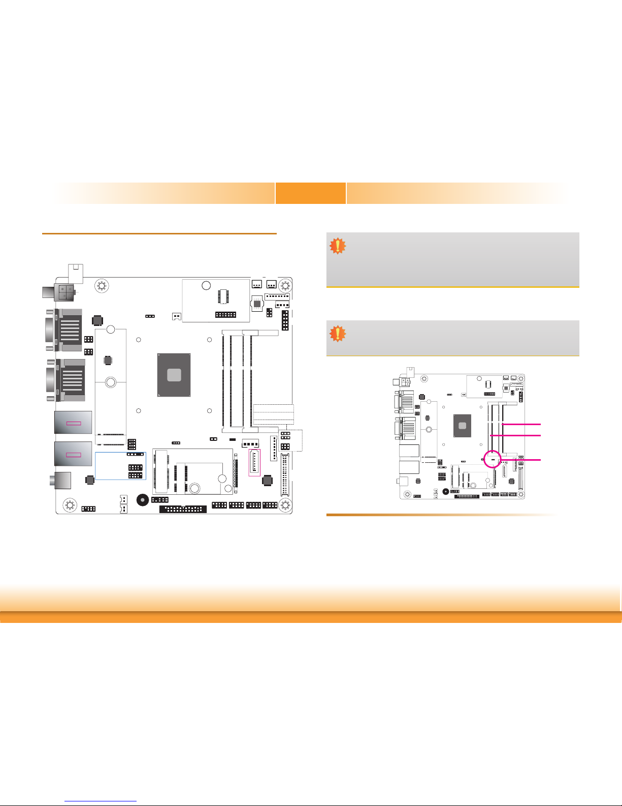
Board Layout.................................................................................................8
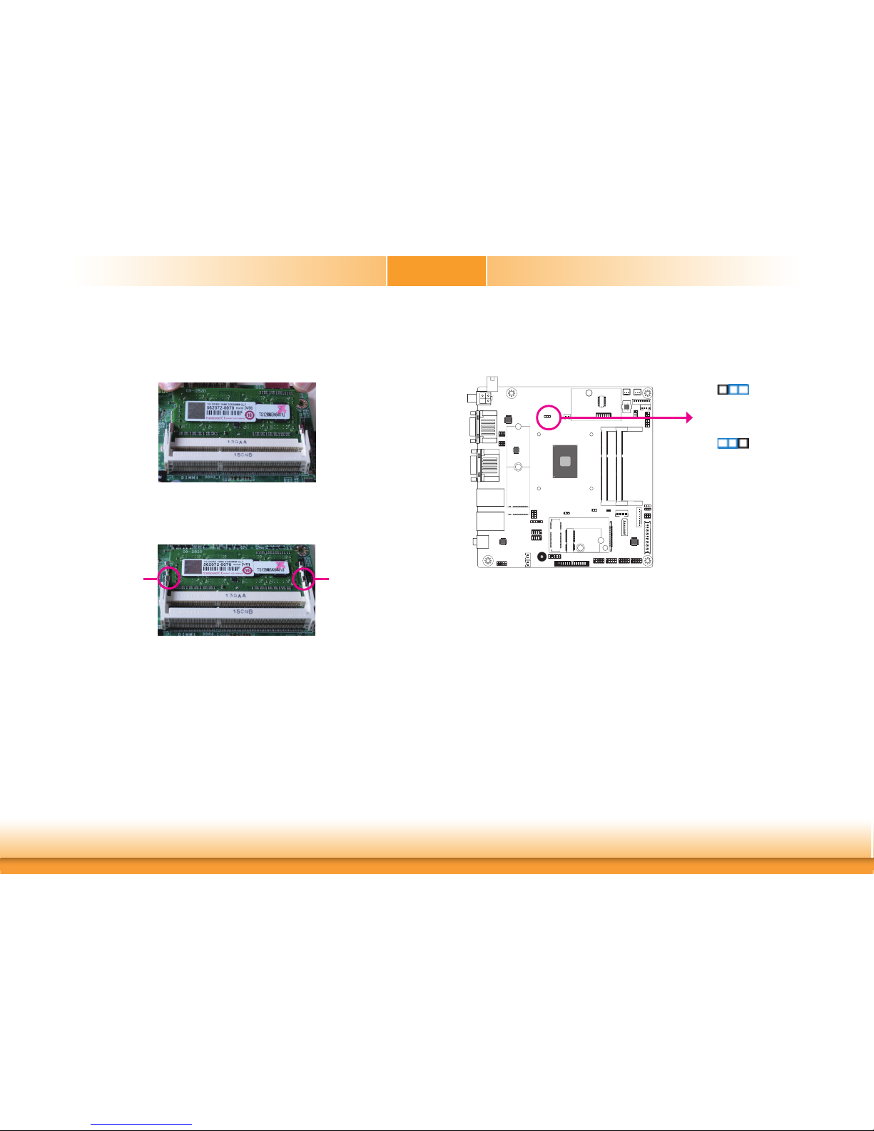
System Memory............................................................................................ 8
Installing the SODIMM Module ...................................................................... 9
Jumper Settings ......................................................................................... 10
Clear CMOS................................................................................................ 10
COM1/COM2 RS232/Power Select................................................................ 11
LCD/Inverter Power Select .......................................................................... 12
Backlight Brightness Select.......................................................................... 12
Panel Power Select ..................................................................................... 13
M.2 M Key PCIe/SATA Signal Select ............................................................. 13
KB/MS Power Select.................................................................................... 14
Rear Panel I/O Ports................................................................................. 15
12V DC-in .................................................................................................. 15
Graphics Interfaces..................................................................................... 16
RJ45 LAN Ports........................................................................................... 16
USB Ports................................................................................................... 17
COM (Serial) Ports...................................................................................... 18
Audio ......................................................................................................... 19
I/O Connectors ........................................................................................... 20
SATA (Serial ATA) Connector ....................................................................... 20
SATA (Serial ATA) Power Connector ............................................................. 20
Speaker Connectors .................................................................................... 21
Digital I/O and Power Connectors................................................................ 21
Cooling Fan Connectors............................................................................... 22
Front Panel Connector ................................................................................ 22
LVDS LCD Panel Connector ......................................................................... 23
LCD/Inverter Power Connector .................................................................... 23
SMBus Connector ....................................................................................... 24
Standby Power LED .................................................................................... 24
Chassis Intrusion Connector ........................................................................ 25
Expansion Slots .......................................................................................... 25
LPC Connector............................................................................................ 26
Connecting the EXT-RS232/RS485 Card to the Motherboard ......................... 26
eDP Connector (optional) ............................................................................ 27
LPT Connector............................................................................................ 28
KB/Ms Connector ........................................................................................ 28
Battery....................................................................................................... 29
Table of Contents

4
Warranty
1. Warranty does not cover damages or failures that arised from misuse of the product,
inability to use the product, unauthorized replacement or alteration of components and
product specifications.
2. The warranty is void if the product has been subjected to physical abuse, improper instal-
lation, modification, accidents or unauthorized repair of the product.
3. Unless otherwise instructed in this user’s manual, the user may not, under any circum-
stances, attempt to perform service, adjustments or repairs on the product, whether in or
out of warranty. It must be returned to the purchase point, factory or authorized service
agency for all such work.
4. We will not be liable for any indirect, special, incidental or consequencial damages to the
product that has been modified or altered.
Static Electricity Precautions
It is quite easy to inadvertently damage your PC, system board, components or devices even
before installing them in your system unit. Static electrical discharge can damage computer
components without causing any signs of physical damage. You must take extra care in han-
dling them to ensure against electrostatic build-up.
1. To prevent electrostatic build-up, leave the system board in its anti-static bag until you are
ready to install it.
2. Wear an antistatic wrist strap.
3. Do all preparation work on a static-free surface.
4. Hold the device only by its edges. Be careful not to touch any of the components, contacts
or connections.
5. Avoid touching the pins or contacts on all modules and connectors. Hold modules or con-
nectors by their ends.
Safety Measures
To avoid damage to the system:
• Use the correct AC input voltage range.
To reduce the risk of electric shock:
• Unplug the power cord before removing the system chassis cover for installation or servic-
ing. After installation or servicing, cover the system chassis before plugging the power
cord.
Important:
Electrostatic discharge (ESD) can damage your processor, disk drive and other com-
ponents. Perform the upgrade instruction procedures described at an ESD worksta-
tion only. If such a station is not available, you can provide some ESD protection by
wearing an antistatic wrist strap and attaching it to a metal part of the system chas-
sis. If a wrist strap is unavailable, establish and maintain contact with the system
chassis throughout any procedures requiring ESD protection.

5
About the Package
The package contains the following items. If any of these items are missing or damaged,
please contact your dealer or sales representative for assistance.
• 1 AL102 motherboard
The board and accessories in the package may not come similar to the information listed
above. This may differ in accordance to the sales region or models in which it was sold. For
more information about the standard package in your region, please contact your dealer or
sales representative.
Before Using the System Board
Before using the system board, prepare basic system components.
If you are installing the system board in a new system, you will need at least the following
internal components.
• Memory module
• Storage devices such as hard disk drive, etc.
You will also need external system peripherals you intend to use which will normally include at
least a keyboard, a mouse and a video display monitor.

6
Chapter 1 - Introduction
Chapter 1
Chapter 1 Introduction www.dfi.com
Specifications
SYSTEM Processor Intel Atom®Processor E3900 Family, BGA 1296
Intel Atom®x7-E3950 Processor, Quad Core, 2M Cache, 1.6GHz (2.0GHz), 12W
Intel Atom®x5-E3940 Processor, Quad Core, 2M Cache, 1.6GHz (1.8GHz), 9.5W
Intel®Pentium®Processor N4200, Quad Core, 2M Cache, 1.1GHz (2.5GHz), 6W
Intel®Celeron®Processor N3350, Dual Core, 2M Cache, 1.1GHz (2.4GHz), 6W
Memory Two 204-pin SODIMM up to 8GB
Dual Channel DDR3L 1867MHz
BIOS Insyde SPI 128Mbit (supports UEFI boot only)
GRAPHICS Controller Intel®HD Graphics GT Series
Feature OpenGL 5.0, DirectX 12, OpenCL 2.1
HW Decode: AVC/H.264, MPEG2, VC1/WMV9, JPEG/MJPEG, HEVC/H.265, VP8, VP9, MVC
HW Encode: AVC/H.264, JPEG/MJPEG, HEVC/H.265, VP8, VP9, MVC
Display 1 x VGA
1 x HDMI
1 x LVDS/eDP (opt.)
VGA: resolution up to 2560x1600 @ 60Hz
HDMI: resolution up to 3840x2160 @ 30Hz
LVDS: dual channel 48-bit, resolution up to 1920x1200 @ 60Hz
eDP: resolution up to 4096x2160 @ 60Hz
Triple
Displays
VGA/HDMI/LVDS
VGA/HDMI/eDP (opt.)
EXPANSION Interface 1 x M.2 M key (support 2242/2280) (PCIe/SATA3.0)
1 x M.2 E key (support 2230) (PCIe/USB2.0)
1 x Full-size Mini PCIe (PCIe2.0/USB2.0) (opt.)
AUDIO Audio
Codec
Realtek ALC269Q
ETHERNET Controller 2 x Realtek RTL8111H-CG
REAR I/O Ethernet 2 x GbE (RJ-45)
USB 4 x USB 3.0
Display 1 x VGA
1 x HDMI
Audio 1 x Line-out (opt.)
Serial 2 x RS-232/422/485 (RS232 w/ power) (RS422/485 opt.) (DB-9)
INTERNAL I/O Serial 4 x RS-232 (2.0mm pitch) (opt.)
USB 4 x USB 2.0 (2.0mm pitch)
1 x USB 2.0 (2.54mm pitch) or 1 x Vertical USB 2.0 Type A (opt.)
Display 1 x LVDS LCD Panel Connector
1 x LCD/Inverter Power
1 x eDP LCD Panel Connector (opt.)
Audio 1 x Audio (Line-out/Mic-in)
SATA 1 x SATA 3.0 (up to 6Gb/s)
1 x SATA power
DIO 1 x 8-bit DIO
LPC 1 x LPC (supports LPC EXT-RS232/RS485 module)
SMBus 1 x SMBus
WATCHDOG
TIMER
Output &
Interval
System Reset, Programmable via Software from 1 to 255 Seconds
SECURITY TPM TPM 2.0 (opt.)
POWER Type Single 12V +/-10% DC
Connector DC-in Jack (opt.)
Right Angle Connector (4-pin) (opt.)
Vertical Type Connector (4-pin)
RTC Battery CR2032 Coin Cell
OS SUPPORT
(UEFI ONLY) Microsoft Windows 10 64-bits (LTSB)
ENVIRONMENT Temperature Operating: 0 to 50°C
Storage: -30 to 60°C
Humidity Operating: 5 to 90% RH
Storage: 5 to 90% RH
MECHANICAL Dimensions Mini-ITX Form Factor
170mm (6.7") x 170mm (6.7")
Height PCB: 1.6mm
Top Side: 40mm, Bottom Side: 3.3mm

7
Chapter 1
Chapter 1 Introduction www.dfi.com
Features
• Watchdog Timer
The Watchdog Timer function allows your application to regularly “clear” the system at the set
time interval. If the system hangs or fails to function, it will reset at the set time interval so
that your system will continue to operate.
• DDR3L
DDR3L requires less voltage (1.35V) than DDR3 (1.5V). DDR3L SDRAM modules support
1867MHz for DDR modules.
• Graphics
The integrated Intel®HD graphics engine delivers an excellent blend of graphics performance
and features to meet business needs. It provides excellent video and 3D graphics with out-
standing graphics responsiveness. These enhancements deliver the performance and compat-
ibility needed for today’s and tomorrow’s business applications. Supports 1 x VGA, 1 x HDMI
and 1 x LVDS/eDP (eDP optional) interfaces for triple display outputs.
• Serial ATA
Serial ATA is a storage interface that is compliant with SATA 1.0a specification. With speed of
up to 6Gb/s (SATA 3.0), it improves hard drive performance faster than the standard parallel
ATA whose data transfer rate is 100MB/s.
• Gigabit LAN
Two Realtek RTL8111H-CG Ethernet controllers support up to 1Gbps data transmission.
• Audio
The Realtek ALC269Q audio codec provides 4-channel High Definition audio output.
• Wake-On-LAN
This feature allows the network to remotely wake up a Soft Power Down (Soft-Off) PC. It is
supported via the onboard LAN port or via a PCI LAN card that uses the PCI PME (Power Man-
agement Event) signal. However, if your system is in the Suspend mode, you can power-on
the system only through an IRQ or DMA interrupt.
• Wake-On-USB
This function allows you to use a USB keyboard or USB mouse to wake up a system from the
S3 (STR - Suspend To RAM) state.
• ACPI STR
The system board is designed to meet the ACPI (Advanced Configuration and Power Interface)
specification. ACPI has energy saving features that enables PCs to implement Power Manage-
ment and Plug-and-Play with operating systems that support OS Direct Power Management.
ACPI when enabled in the Power Management Setup will allow you to use the Suspend to RAM
function.
With the Suspend to RAM function enabled, you can power-off the system at once by pressing
the power button or selecting “Standby” when you shut down Windows®without having to go
through the sometimes tiresome process of closing files, applications and operating system.
This is because the system is capable of storing all programs and data files during the entire
operating session into RAM (Random Access Memory) when it powers-off. The operating ses-
sion will resume exactly where you left off the next time you power-on the system.
• Power Failure Recovery
When power returns after an AC power failure, you may choose to either power-on the system
manually or let the system power-on automatically.
• USB
The system board supports the new USB 3.0. It is capable of running at a maximum transmis-
sion speed of up to 5 Gbit/s (625 MB/s) and is faster than USB 2.0 (480 Mbit/s, or 60 MB/s)
and USB 1.1 (12Mb/s). USB 3.0 reduces the time required for data transmission, reduces
power consumption, and is backward compatible with USB 2.0. It is a marked improvement in
device transfer speeds between your computer and a wide range of simultaneously accessible
external Plug and Play peripherals.

www.dfi.com
8
Chapter 2 Hardware Installation
Chapter 2
Chapter 2 - Hardware Installation
Board Layout
Buzzer
1
eDP (opt.)
40
1
1
COM 6 (opt.)
9
1
911
99
COM 5 (opt.)
COM 4 (opt.)
COM 3 (opt.)
Standby
Power LED
SATA 0
1
SATA 3.0
Mini PCIe (opt.)
5
6
1
2
5
2222
1
10
92
Front Audio
Realtek
ALC269Q
Battery
Clear CMOS (JP6)
1
1
1
12
M.2 M Key PCIe/SATA
Signal Select (JP3) KB/MS Power
Select (JP14)
1 3
3
10
18
3
3
2
3
DDR3L_1 SODIMM
DDR3L_2 SODIMM
1
1
SPI Flash
BIOS
1
1
5
SMBus
2
11
1
COM 1
RS232/Power
Select (JP5)
PTN
3460
PTN3460
Digital
I/O
Power
Digital I/O
System
Fan 1
System
Fan 2
2
4
ASM1442K
PTN
3460
LAN 2
USB 3.0
USB 2/4
LAN 1
USB 3.0
USB 0/1
COM 1
HDMI
COM 2
VGA
1
2
3
3
1
LCD/
Inverter
Power
2
40
1
39
LVDS
LCD
Panel
8
1
Chassis Intrusion
2
Panel Power Select (JP8)
1
102
USB 7/8
USB 2.0
9
1
102
9
1
102
9
1
102
9
USB 9/10
USB 3 or
Vertical USB 3 (opt.)
TPM 2.0 (opt.)
LPC
113
2
14
Intel
M.2 M Key
6
1
2
5
COM 2
RS232/Power
Select (JP2)
Line-out
(opt.)
PTN
3460
PTN3355
Speaker R
(opt.)
Speaker L
(opt.)
1
2
1
2
Front
Panel
Backlight Brightness Select
(JP9)
LCD/Inverter Power Select
(JP10)
14
SATA Power
Atom/
Pentium/
Celeron
KB/MS
19
10 2
1
2
25
LPT
M.2 E Key
4-pin
Vertical
Type
4-pin
Right
Angle
(opt.)
DC-in
(opt.)
1
1
6
5
(JP9)
(JP10)
(JP8)
System Memory
Features
• Two 204-pin SODIMM up to 8GB
• Dual Channel DDR3L 1867MHz
Important:
Electrostatic discharge (ESD) can damage your board, processor, disk drives, add-in
boards, and other components. Perform installation procedures at an ESD workstation
only. If such a station is not available, you can provide some ESD protection by wear-
ing an antistatic wrist strap and attaching it to a metal part of the system chassis. If
a wrist strap is unavailable, establish and maintain contact with the system chassis
throughout any procedures requiring ESD protection.
Important:
When the Standby Power LED lights red, it indicates that there is power on the sys-
tem board. Power-off the PC then unplug the power cord prior to installing any de-
vices. Failure to do so will cause severe damage to the motherboard and components.
PTN
3460
PTN
3460
PTN
3460
DDR3L_1
DDR3L_2
Standby
Power LED

www.dfi.com
9
Chapter 2 Hardware Installation
Chapter 2
The system board supports the following memory interface.
Single Channel (SC)
Data will be accessed in chunks of 64 bits (8B) from the memory channels.
Dual Channel (DC)
Data will be accessed in chunks of 128 bits from the memory channels. Dual channel provides
better system performance because it doubles the data transfer rate.
Installing the SODIMM Module
1. Make sure the PC and all other peripheral devices connected to it has been powered down.
2. Disconnect all power cords and cables.
3. Locate the SODIMM socket on the system board.
4. Note the key on the socket. The key ensures the module can be plugged into the socket in
only one direction.
Note:
The system board used in the following illustrations may not resemble the actual
board. These illustrations are for reference only.

www.dfi.com
10
Chapter 2 Hardware Installation
Chapter 2
6. Push down the module until the clips at each end of the socket lock into position. You will
hear a distinctive “click”, indicating the module is correctly locked into position.
Clip
5. Grasping the module by its edges, align the module into the socket at an approximately 30
degrees angle. Apply firm even pressure to each end of the module until it slips down into
the socket. The contact fingers on the edge of the module will almost completely disappear
inside the socket.
Clip
Jumper Settings
Clear CMOS
If you encounter that CMOS data becomes corrupted, you can reconfigure the system with the
default values stored in the ROM BIOS.
To load the default values stored in the ROM BIOS, please follow the steps below.
1. Power-off the system and unplug the power cord.
2. Set JP6 pins 2 and 3 to On. Wait for a few seconds and set JP6 back to its default setting,
pins 1 and 2 On.
3. Now plug the power cord and power-on the system.
PTN
3460
PTN
3460
PTN
3460
JP6
2-3 On:
Clear CMOS
1-2 On:
Normal (default)
312
312

www.dfi.com
11
Chapter 2 Hardware Installation
Chapter 2
COM1/COM2 RS232/Power Select
JP5 (for COM 1) and JP2 (for COM 2) are used to configure Serial COM ports to pure RS232
or RS232 with power. The pin functions of COM 1 and COM 2 will vary according to JP5’s and
JP2’s setting respectively.
PTN
3460
PTN
3460
PTN
3460
JP2
JP5
COM 1/COM 2
Pin RS232 RS232 with power
1DCD- +12V
2RD RD
3TD TD
4DTR- DTR-
5GND GND
6DSR- DSR-
7RTS- RTS-
8CTS- CTS-
9RI- +5V
JP5 (for COM 1)
1-3 (RI-), 2-4 (DCD-) On:
RS232 (default)
3-5 (+5V), 4-6 (+12V) On:
RS232 with power
JP2 (for COM 2)
1-3 (RI-), 2-4 (DCD-) On:
RS232 (default)
3-5 (+5V), 4-6 (+12V) On:
RS232 with power
135
24
6
135
246
COM 1
COM 2 135
246
135
246
12345
6789

www.dfi.com
12
Chapter 2 Hardware Installation
Chapter 2
Backlight Brightness Select
JP9 is used to select the power level of backlight brightness control: +3.3V (default) or +5V.
1-2 On:
+3.3V (default)
2-3 On:
+5V
PTN
3460
PTN
3460
PTN
3460
JP9
312
312
LCD/Inverter Power Select
PTN
3460
PTN
3460
PTN
3460
1-2 On:
+12V (default)
2-3 On:
+5V
13 2
132
JP10
JP10 is used to select the power level of LVDS/eDP (optional) LCD inverter connector.
Important:
Before powering-on the system, make sure that the power settings of JP9 match the
power specification of backlight control. Selecting the incorrect voltage will seriously
damage the backlight.

www.dfi.com
13
Chapter 2 Hardware Installation
Chapter 2
M.2 M Key PCIe/SATA Signal Select
2-3, 5-6, 8-9, 11-12 On:
SATA (default)
1-2, 4-5, 7-8, 10-11 On:
PCIe
1210
JP3 is used to select the M.2 M Key signal: SATA (default) or PCIe.
PTN
3460
PTN
3460
PTN
3460
JP3 31
1210
Panel Power Select
PTN
3460
PTN
3460
PTN
3460
JP8
1-2 On:
+12V
3-4 On:
+5V
5-6 On:
+3.3V (default)
5
246
13
JP8 is used to select the power supplied with the LCD panel.
Important:
Before powering-on the system, make sure that the power settings of JP8 match the
LCD panel’s specification. Selecting the incorrect voltage will seriously damage the
LCD panel.
5
246
13
5
246
13
31

www.dfi.com
14
Chapter 2 Hardware Installation
Chapter 2
JP14 is used to select the power of the Keyboard/Mouse.
KB/MS Power Select
132
132
PTN
3460
PTN
3460
PTN
3460
JP14
1-2 On:
+5VSB (default)
2-3 On:
+5V

www.dfi.com
15
Chapter 2 Hardware Installation
Chapter 2
Rear Panel I/O Ports
The rear panel I/O ports consist of the following:
• 1 DC-in
• 2 Serial COM ports
• 1 HDMI port
• 1 VGA port
• 2 RJ-45 LAN ports
• 4 USB 3.0 ports
• 1 Line-out jack (optional)
COM 1
HDMI
COM 2 LAN 1 LAN 2
USB 3.0
VGA
Line-out (opt.)
DC-in
12V DC-in
DC-in
PTN
3460
PTN
3460
PTN
3460
This 4-pin vertical type connector is considered a low power solution. Connect a DC power
cord to this connector. Using a voltage more than the recommended range may fail to boot
the system or cause damage to the system board.
The 4-pin vertical type connectoron the system board co-lays with a DC-in jack (optional) or
4-pin right angle connector (optional) as the photo displayed below.
DC-in (optional)
4-pin Vertical Type (default)
4-pin Right Angle
(optional)

www.dfi.com
16
Chapter 2 Hardware Installation
Chapter 2
RJ45 LAN Ports
LAN 1
Features
LAN 2
LAN 2
LAN 1
• Two Realtek RTL8111H-CG Ethernet controllers
The two LAN ports allow the system board to connect to a local area network by means of a
network hub.
BIOS Setting
Configure the onboard LAN ports in the Advanced menu (“ACPI Configuration” submenu) of
the BIOS. Refer to the chapter 3 for more information.
Driver Installation
Install the LAN drivers. Refer to the chapter 4 for more information.
PTN
3460
PTN
3460
PTN
3460
Graphics Interfaces
HDMI Port
The HDMI port which carries both digital audio and video signals is used to connect a LCD
monitor or digital TV that has the HDMI port.
VGA Port
The VGA port is used for connecting a VGA monitor. Connect the monitor’s 15-pin D-shell cable
connector to the VGA port. After you plug the monitor’s cable connector into the VGA port,
gently tighten the cable screws to hold the connector in place.
BIOS Setting
Configure the display devices in the advanced menu (“Video Configuration” submenu) of the
BIOS. Refer to the chapter 3 for more information.
Driver Installation
Install the graphics driver. Refer to the chapter 4 for more information.
The display ports consist of the following:
• 1 HDMI port
• 1 VGA port
VGA
PTN
3460
PTN
3460
PTN
3460
HDMI

www.dfi.com
17
Chapter 2 Hardware Installation
Chapter 2
USB Ports
USB 1
USB 0
USB 2
USB 3.0
PTN
3460
PTN
3460
PTN
3460
10
VCC
-Data
+Data
GND
VCC
-Data
+Data
GND
N.C.
9
1
2
USB 3 or
Vertical USB 3 (opt.)
USB 9-10
USB 4
USB 7-8
The USB device allows data exchange between your computer and a wide range of simultane-
ously accessible external Plug and Play peripherals.
The system board is equipped with 4 onboard USB 3.0 ports (USB 0-1/2-4) at the rear panel
I/O ports. The 10-pin connectors allow you to connect 4 additional USB 2.0 ports (USB 7-8/9-
10). The 5-pin connector allows you to connect 1 additional USB 2.0 port (USB 3).The ad-
ditional USB ports may be mounted on a card-edge bracket. Install the card-edge bracket to
an available slot at the rear of the system chassis and then insert the USB port cables to a
connector.
BIOS Setting
Configure these onboard USB devices in the Advanced menu (“USB Configuration” submenu)
of the BIOS. Refer to the chapter 3 for more information.
Driver Installation
You may need to install the proper drivers in your system operation to use the USB device.
Refer to your operating system’s manual or documentation for more information.
USB 2.0
USB 3.0
Wake-On-USB Keyboard/Mouse
The Wake-On-USB Keyboard/Mouse function allows you to use a USB keyboard or USB mouse
to wake up a system from the S3 (STR - Suspend To RAM) state.
USB 2.0
1
5
GND
-Data
+Data
VCC

www.dfi.com
18
Chapter 2 Hardware Installation
Chapter 2
COM (Serial) Ports
PTN
3460
PTN
3460
PTN
3460
COM 1/2:
RS232/422/485
(422/485 opt.)
COM 1
COM 3/4/5/6 (opt.): RS232
Pin Pin Assignment
1DCD-
2RD
3TD
4DTR-
5GND
6DSR-
7RTS-
8CTS-
9RI-
2
1
9
COM 3/4/5/6 (opt.)
COM 1 and COM 2 can be configured as RS232, RS422 and RS485 (RS422/RS485 opt.) by
BIOS setting. The pin functions are listed at right. The pin functions of COM ports 1/2 will also
vary according to JP5’s and JP2’s settings. JP5 and JP2 are used to configure the Serial COM
ports 1/2 to pure RS232 or RS232 with power. Refer to “COM1/COM2 RS232/Power Select” in
this chapter for more information.
COM 3/4/5/6 (opt.) are fixed at RS232. The pin functions are listed at right.
The serial ports are asynchronous communication ports with 16C550A-compatible UARTs that
can be used with modems, serial printers, remote display terminals, and other serial devices.
Connecting External Serial Ports
Your COM port may come mounted on a card-edge bracket. Install the card-edge bracket to
an available slot at the rear of the system chassis then insert the serial port cable to the COM
connector. Make sure the colored stripe on the ribbon cable is aligned with pin 1 of the COM
connector.
BIOS Setting
Configure the serial COM ports in the Advanced menu (“SIO NUVOTON6112D” submenu) of
the BIOS. Refer to the chapter 3 for more information.
COM 2
12345
6789
Pin RS232 RS422 Full Duplex
(opt.)
RS485
(opt.)
1DCD- RX+ DATA+
2RD RX- DATA-
3TD TX+ N.C.
4DTR- TX- N.C.
5GND GND GND
6DSR- N.C. N.C.
7RTS- N.C. N.C.
8CTS- N.C. N.C.
9RI- N.C. N.C.
COM 1/2

www.dfi.com
19
Chapter 2 Hardware Installation
Chapter 2
Audio
Rear Audio
The system board is equipped with 1 optional audio jack (Line-out). A jack is a one-hole con-
necting interface for inserting a plug.
• Line-out Jack (Lime) (optional)
This jack is used to connect a headphone or external speakers.
Front Audio
The front audio connector allows you to connect to the second line-out and mic-in jacks that
are at the front panel of your system.
BIOS Setting
Configure these onboard Audio devices in the Advanced menu (“Audio Configuration” sub-
menu) of the BIOS. Refer to the chapter 3 for more information.
Driver Installation
Install the audio driver. Refer to the chapter 4 for more information.
Rear Audio
PTN
3460
PTN
3460
PTN
3460
Line-out (optional)
Front Audio
1
Mic2-L
HP-out-R
GND
GND
N.C.
2
10
Mic2-JD
HP-out-JD
9
Mic2-R
HP-out-L

www.dfi.com
20
Chapter 2 Hardware Installation
Chapter 2
SATA (Serial ATA) Connector
• 1 Serial ATA 3.0 port with data transfer rate up to 6Gb/s (SATA 0)
• Integrated Advanced Host Controller Interface (AHCI) controller
The Serial ATA connector is used to connect Serial ATA device. Connect one end of the Serial
ATA data cable to a SATA connector and the other end to your Serial ATA device.
BIOS Setting
Configure the Serial ATA drive in the Advanced menu (“SATA Configuration” submenu) of the
BIOS. Refer to the chapter 3 for more information.
Features
SATA 0
RXN
GND
TXP
TXN
GND
RXP
GND
PTN
3460
PTN
3460
PTN
3460
SATA 3.0 6Gb/s
SATA (Serial ATA) Power Connector
The SATA power connectors supply power to the SATA drive. Connect one end of the provided
power cable to the SATA power connector and the other end to your storage device.
PTN
3460
PTN
3460
PTN
3460
SATA
Power 0
+12V
+5V Ground
1
Ground
4
I/O Connectors
1
7
Other manuals for AL102
2
Table of contents
Other DFI Motherboard manuals