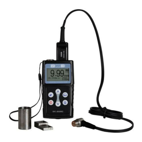
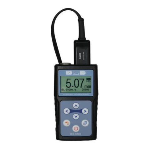
DGC DC-5000 User manual

UTThicknessGauge
DC‐5000
InstructionManual

CONTENTS
1.GENERALDESCRIPTION...............................................................................‐1‐
2.STANDARDDELIVERY..................................................................................‐1‐
3.TECHNICALSPECIFICATIONS........................................................................‐2‐
4.OVERVIEW..................................................................................................‐2‐
5.KEYPADFUNCTIONS....................................................................................‐3‐
6.DISPLAYSCREEN..........................................................................................‐5‐
7.QUICKSTARTUPGUIDE...............................................................................‐8‐
8.MENU.......................................................................................................‐10‐
8.1MEA.(MEASUREMENT)..................................................................................‐10‐
8.1.1T‐EMode:.....................................................................................................‐ 10‐
StandardMeasurement:..................................................................................‐ 11‐
MinimumMeasurement:.................................................................................‐ 11‐
Differencemode:..............................................................................................‐ 12‐
Averagemode:.................................................................................................‐ 13‐
LimitationMode...............................................................................................‐ 14‐
8.1.2E‐EMode......................................................................................................‐ 14‐
8.2SET..............................................................................................................‐15‐
8.2.1Velocityrate.................................................................................................‐ 15‐
Materials..........................................................................................................‐ 16‐
Velocityinput...................................................................................................‐ 17‐
Velocitymeasurement.....................................................................................‐ 18‐
Velocitystorage................................................................................................‐ 19‐
8.2.2Resolution....................................................................................................‐ 19‐
8.2.3ProbeCalibration.........................................................................................‐ 20‐
8.2.4Measurementrate.......................................................................................‐ 21‐
8.2.5Automeasurement......................................................................................‐ 21‐
8.2.6Manualmeasurement..................................................................................‐ 22‐
8.2.7Rectification.................................................................................................‐ 24‐
8.2.8A‐SCANcustomsetting.................................................................................‐ 25‐
8.2.9B‐SCANdisplayrange...................................................................................‐ 26‐
8.3MEM...........................................................................................................‐26‐
8.3.1Setanewfile................................................................................................‐ 27‐
8.3.2MemoryRead...............................................................................................‐ 27‐
8.3.3Deleteafile..................................................................................................‐ 28‐
8.3.4Deleteallfiles...............................................................................................‐ 28‐
8.4FUN.............................................................................................................‐29‐
8.4.1Swichoffmode.............................................................................................‐ 29‐
8.4.2Languages.....................................................................................................‐ 29‐
8.4.3Contrast........................................................................................................‐ 29‐
8.4.4Default..........................................................................................................‐ 30‐
9.MEASURINGTECHNOLOGY........................................................................‐30‐
9.1MEASURINGMETHODS....................................................................................‐30‐
9.2PIPELINEMEASUREMENTMETHOD.....................................................................‐31‐
10.MAINTENANCEANDPRECAUTIONS.........................................................‐31‐
10.1POWERCHECK..............................................................................................‐31‐
10.2PRECAUTIONS..............................................................................................‐31‐
10.2.1Generalprecautions..........................................................................‐ 31‐
10.2.2Precautionduringthemeasuring......................................................‐ 31‐
APPENDIX:SOUNDVELOCITYMEASUREMENTCHART..................................‐32‐

‐1‐
1.GeneralDescription
DC‐5000isavisualA/Bscanultrasonicthicknessgaugewithhighenergy.It
isaMulti‐Modethicknessgaugethathastheabilitytomeasureverythick
compositematerialormaterialthatisveryhardforultrasonictogothrough.
Thisunitcanmeasurethethicknessofmetallicandnon‐metallicmaterials
suchassteel,aluminum,titanium,plastics,ceramics,glassandanyother
goodultrasonicwaveconductor.
DC‐5000comeswithfollowingfeatures:
●LargecolorTFTdisplay
●Automaticproberecognition,
●Automaticprobezerocalibration
●Automaticallylocatesthedetectionpointifthemeasurementisoutofthe
viewabledisplayarea.
●AllowusertoadjusttherangeofGAIN,RANGE,DELAY,GATE,BLANK,
E‐BLANKinmanual‐measurementmode.
●Limitationsetting,alarmwithsoundanddisplay.
●Multi‐language
●Memoryof100filesX100data,transferdatatoPCwithoutsoftware,
availableforanywindowsoperatingsystems.
●Measurementscreenautomaticfrozen,whichmakeiteasytoanalyzethe
dataforusers.
2.StandardDelivery
●MainUnit
●Transit‐Echotransducer(S1025)
●75MLCouplant
●Build‐incalibrationblock(Thickness=4mm,Velocity=5920m/s)
●USBCable
●Carryingcase
●Operatingmanual
●CalibrationCertificate

‐2‐
3.TechnicalSpecifications
4.Overview
1.LCDScreen
2.KeyPad
3.BatteryPack
4.Transducerport
5.StandardTestBlock
6.USBport
MeasurementrangeT‐E:20mm~590mm
Resolution0.01mm(0.001inch),0.1mm(0.01inch)
Velocityrange1000m/s~9999m/s
Measurementrate2/sand10/sinfastmode
Averagemode2to9timesaveragemeasurement
LimitedsettingWithLow‐highindicationandalarm
MeasuringUnitsmm/inch
MemoryMemoryof10,000readingsin100files
DataoutputUSBtoPCwithoutsoftware
Display320×240TFTColorLCD
Battery 2xAABatteries
Operating‐20℃~+50℃
Dimensions133mm(L)×75mm(W)×29mm(H)
Weight0.26kg(includingbatteries)
2
3
4
6
1

‐3‐
5.KeypadFunctions
On&OffKey
Function1ItisusedtopowertheuniteitherONorOFF.
Function2Pressingthiskeytoescapethemenusettingandreturn
backtothemainmeasurementscreen.
MenuKey
Function1Itisusedtoenterthemenuandconfirmtheselection.
Function2ItisasashortcutkeyinA‐scanmode.Afterfinishone
A‐scanmeasurement(keepingtheParametersfieldin
highlight),pressthiskeytostorethecurrentset‐up
parametersintotheCUSTOMSETTING.
F1Key
Function1InA‐scanmanualmode,itisatogglebuttonmainly
usedtosetuptheparametersRANGE,GAIN,DELAY,
GATE,BLANKbyadjustingthekey .
Function2InB‐scanmode,pressthiskeytoclearcurrentgragh
Andreadyfornextmeasurement.
F2Key
Function1Pressthiskeytotogglebetweendisplayviewoptions‐
A‐Scan,B‐SCANandDIGITS.
Function2InA‐scanmode,pressthiskeytosavecurrentcustom
setupthathasbeenmodifiedorcreatedbytheuser.

‐4‐
UPkey
Function1Itisusedtonavigatethemenusandincreasevalues
whilesettingtheparameters.
Function2Inmeasurementmode,pressthiskeytostorethe
currentmeasurementreading.
DOWNkey
Function1Itisusedtonavigatethemenusanddecreasevalues
whilesettingtheparameters.
Function2Inthemeasurementmode,itisusedasthecalibration
Key.Puttheprobeintheair,pressthiskeyto
completethecalibration.
LEFTKey
Function1Itisusedtonavigatethemenusanddecreasevalues
whilesettingtheparameters.
Function2InA‐SCANmode,pressthiskeytoenterCUSTOM
SETTINGscreentoopenasetupthathasbeensaved
before.
Function3InB‐Scanmode,pressthiskeytocontrolthethickness
readingindicator(thesmallyellowtriangle).
RIGHTKey
Function1Itisusedtonavigatethemenusandincreasevalues
whilesettingtheparameters.
Function2InDIGISandA‐SCANmode,thereadoutwillbe
changedbetweenmmtoinchbypressingthiskey.
Function3InB‐Scanmode,pressthiskeytocontrolthethickness
readingindicator(thesmallyellowtriangle).

‐5‐
6.DisplayScreen
A‐SCANMODE
FullwaveHalf+wave
1.Thicknessreading‐Digitalreadoutofthickness.Displaywithwhitecolormeansin
testing,withbluecolormeansfrozen.
2.The1stbackwallindicator‐TheRed▼indicatesthefirstbackwall
3.Gateindicator‐Theredlinecanbeadjustedupordown.
4.Fullwaveform‐Displaywithgreencolormeansintesting,withbluecolormeans
Infrozen)
5.Blankindicator‐ThelengthofRedlinechangeswiththeBLANKnumberadjusted.
6.Delayvalueindicator
7.Parametersfield‐Gain,Delay,Blank,E‐blank,Rangeadjustable
8.Memorylocation‐Files100X100datacanbestored
9.Transducermodel‐Thetransducerautomaticallyrecognizesanddisplay
10.Velocity
11.EndofRangeindicator
12.Powerlife
13.Measuringmode
14.Measuringunit‐millimetersorinches

‐6‐
BIGDIGITSMODE
1.Velocity
2.Transducermodel‐Thetransducerautomaticallyrecognizesanddisplay
3.Measuringmode
4.ThicknessReading‐Digitalreadoutofthickness.Displaywithwhitecolormeans
intesting,withbluecolormeansfrozen.
5.Gainvalue‐Canbeadjustedfrom10‐50
6.Powerlife
7.Measuringunit‐millimetersorinches
8.Memorylocation‐Files100X100datacanbestored
9.Hotmenuindicators‐Pressthecorrespondingbutton,easytoconvertsthe
displayorfunction.

‐7‐
B‐SCANMODE
1.Thicknessreading‐Digitalreadoutofthickness.Displaywithwhitecolormeans
intesting,withbluecolormeansfrozen.
2.Min.valueindicator‐Indicateswheretheminimumislocated.
3.Bscangraphic
4.Thicknessreadingindicator‐Indicateswherethecurrentthicknessreadingis
Located.
5.Gainvalue‐Canbeadjustedfrom10‐50.
6.Velocity
7.Transducermodel‐Thetransducerautomaticallyrecognizesanddisplay.
8.Powerlife
9.Bscandisplayrange‐Displaystherangesetinthemenuandautodividesinto5
equalparts.
10.Min.valuereading‐Displaystheminimumvalueofworkpiece.
11.Hotmenuindicators‐Pressthecorrespondingbutton,easytoconvertsthe
displayorfunction.

‐8‐
7.Quickstartupguide
Stepone:SelectingtheTransducerandProbezero&calibration
Rightnow,thereisprobeS1025availableanditsinformationisasbelow:
TypeFreq.
(MHz)
Dia.
(mm)
Meas.Rang
(mm)
Working
Temp. Application
S102512520~590<60℃Usedinthemeasurementof
compositematerials
Plugintransducer;turnonthemainunitusingthe Key.Thegaugedoes
autocalibrationofthetransducer,thuseliminatingtheneedforanon‐block
zero.Afterturningonthegauge,thescreenflashestheSeriesNo.and
softwareversion,andthen,itcomesintothemeasurementmodedirectly.
Ifusersturningontheunitwithoutthetransducer,screenwillremindto
"Plugintheprobe".Atthismoment,pleaseinsertatransducerintothe
socket,thegaugedirectlycomesintothemeasurementmodeafterAuto
calibration.
Notice:Pleaseusethestandardtransduceroffered.Otherwisetheunitdoes
notworknormallyanddisplaying“Error”.
Ifusersfeelthethicknessreadingisincorrectduringthemeasurement,
pleaseputtheprobeintheair,andpressforzerocalibrationatany
time.
Notice:ForAutocalibration,makesurethetransducerisnotcoupledtothe
testpiecewhenthegaugeisfirstturnedonandthereisnocouplantonthe
endofthetransducer.Thetransducershouldalsobeattheroom
temperature,cleanwithoutanynoticeablewear.
StepTwo:Treatmentofthemeasuredsurface
Whenthesurfacetobemeasuredistooroughorrustyheavily,please
performthetreatmentaccordingtothefollowingmethods:
1.Cleanthemeasuredsurfacebygrinding,polishingorfiling,etc.oruse
couplingagentwithhighviscosityforthat.
2.Usecouplingagentsontheworkpiecesurfacetobemeasured.
3.Takemultiplemeasurementsaroundthesametestingpoint.

‐9‐
StepThree:Settingvelocity
Soundvelocityplaysanimportantroleinmeasurement.Differentmaterialis
ofdifferentsoundvelocity.Whenthesoundvelocityisincorrect,itwillcause
wrongmeasuredresults.Thereare3waystosetthematerial'ssound
velocity,whichare:
1.Directlyselectpresetmaterialvelocity.Pleasereferto8.2.1.2onpage3.
2.Inputthenewvelocitywhichisnotpresetintothemenu.Pleasereferto
8.2.1.3onpage4.
3.Gettheaccuratesoundvelocityoftheworkpiecewhichthethicknessis
known.Pleasereferto8.2.1.4onpage4.
StepFour:Measurement
TheDC‐5000isnowreadytomeasure.Therearefourdifferent
measurementviewoptions,A‐ScanRF+,A‐ScanHALF+,B‐ScanandDIGITS,
eachwithaspecificpurpose.
A‐ScanRF+:Itshowsboththepositiveandthenegativepeaks.
A‐ScanHALF+:Itshowsthepositive.
B‐Scan:Itdisplaysatimebasedcrosssectionviewoftestmaterial.
DIGITS:Itisabasicdigitalthicknessgaugelookandfeel.Thecolorandlarger
digitsmakeitmucheasierfortheoperatortomonitorthethickness
readings.
Usercantogglebetweenthedifferentviewmodeoptionsbypressing .

‐10‐
8.MENU
8.1MEA.(Measurement)
DC‐5000providestwomeasurementmodes,T‐EmodeandE‐Emode.
1)PressthekeytoilluminateMEA.
2)Pressor toselectT‐EorE‐Emode,Press toconfirm.
8.1.1T‐EMode:
WhenT‐Emodeisselected,allprobesareavailable.Andmeasurement
modesofStandard,Minimum,Difference,Averageandlimitationcanbe
selected.

‐11‐
StandardMeasurement:
Withthisfunction,DC‐5000displaysthecurrentmeasurementvalue,
satisfiedwiththenormalmeasuringneeds.
Thefollowingpagesoutlinehowtoenableandsetupthisfeature.
1)PressthekeytoilluminateMEA.
2)Usekeystoscrollthroughthesubmenuitemsuntil
Standardishighlighted.Pressthekeytoconfirm.
3)PressthekeytoexitsettingandDC‐5000isnowreadytoperform
measurements.
MinimumMeasurement:
Whentakingmeasurements,DC‐5000displaysthesmallestthickness
readingitfound.Itissuitablefortestingthecurvaturesurfaceorneedsto
gettheminimumvaluewhichiswidelyusedinthemeasurementof
pipeline.
Notice:itisnotrecommendedtousethisfunctionwhenmeasuringcastiron
oralloymaterials.
Thefollowingpagesoutlinehowtoenableandsetupthisfeature.
1)PressthekeytoilluminateMEA.
2)Usekeystoscrollthroughthesubmenuitemsuntil
Minimumishighlighted.Pressthekeytoconfirm.
3)PressthekeytoexitsettingandDC‐5000isnowreadytoperform
measurements.
S1025

‐12‐
Differencemode:
InthequalityControlenvironment,itissometimesnecessarytoknowthe
differencebetweenanominal(target)thicknessvalueandanactual
thicknessvalue.WiththeDifferencemodeenabled,DC‐5000willdisplay
thepositive(+)ornegative(‐)differencefromanenterednominalvalue.
Thefollowingpagesoutlinehowtoenableandsetupthisfeature.
1)PressthekeytoilluminateMEA.
2)Use keystoscrollthroughthesubmenuitemsuntil
Differenceishighlighted.Pressthekeytoconfirm.TheDisplay
showsasfollows:
3)Presstheor keytomovethecursor,
4)Presstheor keytochangethenumbersandDotposition.The
valuecouldbesetas0.000,00.00and000.00.The1standthelastposition
canbesetnumbers1‐9asacircle.Theotherpositionscanbesetnumbers
1‐9anddotasacircle.Pressthekeytoconfirm.
Note:500.0istheMax.valuecanbeset.IfUsersetsthevalueexceeding
themax.value,theunitwillcorrectitas500.0automatically.
5)PressthekeytoexitandDC‐5000isnowreadytowork.

‐13‐
Averagemode:
Withthisfunction,DC‐5000displaystheaveragevalueof2to9measured
points.Itcanhelpusertocheckthesurfaceplanenessofflatboardand
theirmanufacturingprocess.
Thefollowingpagesoutlinehowtoenableandsetupthisfeature:
1)PressthekeytoilluminateMEA.
2)Usekeystoscrollthroughthesubmenuitemsuntil
Averageishighlighted.Pressthekeytoconfirm.TheDisplay
showsasfollows:
3)Presstheor keytochangethenumbersamong2to9,
4)Pressthekeytoconfirm.
5)PressthekeytoexitsettingandDC‐5000isnowreadytoperform
measurements.

‐14‐
LimitationMode
Thisfunctionallowstheusertosetanaudibleandvisual(Hi/Lo)parameter
whenmeasurements.IfthemeasurementfallsbeloworabovetheHI/LO
limits,setbytheuser,theredHorgreenLwillbedisplayedandthebeeper
sounded.Thisimprovesthespeedandefficiencyoftheinspectionprocessby
eliminatingconstantviewingoftheactualreadingdisplayed.
Thefollowingpagesoutlinehowtoenableandsetupthisfeature:
1)PressthekeyintoMEA.
2)Usekeystoscrollthroughthesubmenuitemsuntil
Limitationishighlighted.Pressthekeytoconfirm.Thedisplay
showsasfollows:
3)Usekeystosetthelow/highlimitation.Thevaluecould
besetas0.000,00.00and000.00.The1standthelastpositioncanbeset
numbers1‐9asacircle.The3rdpositionscanbesetnumbers1‐9anddot
asacircle.Pressthekeytoconfirm.
4)PressthekeytoexitsettingandDC‐5000isnowreadytoperform
measurements.
8.1.2E‐EMode
TheE‐E(echo‐echo)functionisnotavailableowingtosuitableprobeisunder
developingrightnow.

‐15‐
8.2SET.
Thisfunctionallowsusertosetfollowingparametersofmeasurement.
Thefollowingpagesoutlinehowtoenableandsetuptheseparameters.
8.2.1Velocityrate
Soundvelocityplaysanimportantroleinmeasurement.Differenttypesof
materialhavedifferentinherentsoundvelocities.Ifthegaugeisnotsetto
thecorrectsoundvelocity,allofthemeasurementsthegaugemakeswillbe
erroneousbysomefixedpercentage.
Ifthenameorsound‐velocityofthematerialtobemeasuredisknown,the
usercouldselectmaterialnamedirectlyinthemenuMaterials.Orinputthe
knownvelocityinthemenuVelocityInput.
AndtheusercouldmeasurethesoundvelocitybyusingthefunctionVelocity
measurementIfthesound‐velocityofthematerialtobemeasuredis
unknown,buttheexactthicknessofwhichisknow.

‐16‐
Materials
TheDC‐5000presets9commonmaterials'soundvelocity.Theyare:
aluminum,titanium,steel,stainlesssteel,glass,copper,castiron,brass,
polystyrene.
Theusermayopttochoosesuchbasicmaterialtypefromthemenu.It's
importanttonotethatthesevelocitieswillnotalwaysbeanexact
representationofthematerialbeingtested.Usethesevaluesonlyifaclose
approximationisacceptable.
Thefollowingpagesoutlinehowtoenableandsetupthisfeature:
1)PressthekeytoilluminateSET‐Velocityrate‐Materials,
2)Usekeystoscrollthroughthesubmenuitemsuntil
Thetargetmaterialishighlighted.Pressthekeytoconfirm.
3)PressthekeytoexitsettingandDC‐5000isnowreadytoperform
measurements.

‐17‐
Velocityinput
Ifthematerialvelocityisknown,theusermaywishtosimplyenterthe
velocitynumberintotheDC‐5000,ratherthanhavetheDC‐5000calculate
thevelocityvalueonusingaknowthickness.AndDC‐5000alsocanstore4
newvelocitiesascustom.
Thefollowingpagesoutlinehowtoenterthevelocity:
1)PressthekeytoilluminateSET‐Velocityrate,
2)Use keystoscrollthroughthesubmenuitemsuntil
VELOCITYINPUTishighlighted.Pressthekeytoconfirm.
3)Presstheor keytomovethecursor,Pressthe or
Keytochangethenumbers,
4)PressthekeytoconfirmandstoreitintoVelocityStorage,
5)Presstheor keytoIlluminatetheplacewherewanttostore,
Pressthekeytoconfirm.
6)PressthekeytoexitsettingandDC‐5000isnowreadytoperform
measurements.

‐18‐
Velocitymeasurement
Sometimesthesoundvelocityofamaterialisnotknown.Inthiscasea
samplewithaknownthicknesscanbeusedtodeterminethesound
velocity.Itwouldbeveryhandytocarryasetofmechanicalcaliperstouse
inconjunctionwiththeDC‐5000inthefield.
Thefollowingstepsoutlinehowtoenableandsetupthisfeature:
1)Physicallymeasureanexactsampleofthematerialoralocationdirectly
Onthematerialtobemeasuredusingasetofcalipersoradigital
micrometer.
2)Applyadropofcouplantonthetransducerandplacethetransducerin
steadycontactwiththesampleoractualtestmaterial.
3)Thedisplayshouldshowathicknessreading(probablyincorrect).
4)Havingachievedastablereading,removethetransducer.(Ifthe
Displayedthicknesschangesfromthevalueshownwhilethetransducer
Wascoupled,repeatstep3.)
5)PressthekeytoilluminateSET,Use keysto
scrollthroughthesubmenuitemsuntilVelocityMeasurementis
highlighted.Pressthekeytoconfirm.
6)Presstheor keytomovethecursor,pressthe or
keytoadjustthedisplayedvelocityupordown,untilthethicknessvalue
displayedmatchesthethicknessofthesamplepiece.Andnowthe
displayingsoundvelocityvalueisaccurate.
7)PressthekeytoconfirmandstoreitintoVelocityStorage,
8)Presstheor keytoIlluminatethetargetplace,Pressthe
keytoconfirm.
9)PressthekeytoexitsettingandDC‐5000isnowreadytoperform
measurements.
Table of contents
Other DGC Measuring Instrument manuals
Popular Measuring Instrument manuals by other brands

Ambient Weather
Ambient Weather PM2.5IN user manual
Parkside
Parkside PKLL 8 A1 Translation of the original instructions
Raycus
Raycus RFL-C Series user guide
ComsecTR
ComsecTR TOTAL RECALL DESKTOP Installation & Administration Guide
quadient
quadient IS-280 Replacement Part Guide
Endress+Hauser
Endress+Hauser Analytik Jena Biometra TS1 ThermoShaker Short manual
