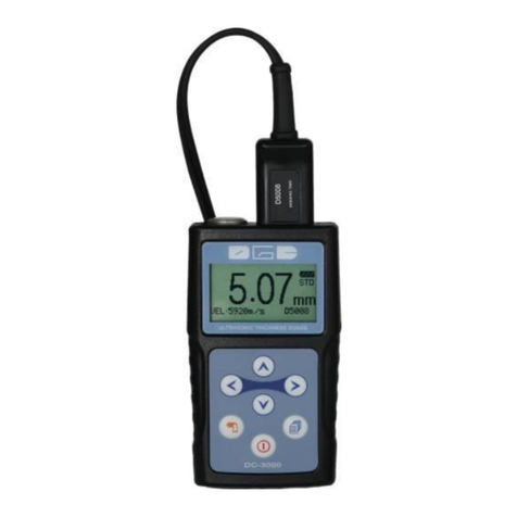
DGC DC-2000C Series User manual

Ultrasonic Thickness Gauge
DC-2000C series
Instruction Manual
V. 7.11

CONTENTS
1. General Description......................................................................................1
2. Technical Specifications................................................................................1
3. Standard Delivery.........................................................................................2
4. Overview the Display Unit...........................................................................2
5. Keypad Functions.........................................................................................3
6. Display Screen...............................................................................................5
7. Preparation before measurement................................................................5
【7.1】Preparation of the instrument............................................................5
【7.2】Selection of the Probe.......................................................................6
【7.3】Treatment of the measured surface ...................................................6
8. Basic Operations…………………………………………………...............7
【8.1】Switch on..........................................................................................7
【8.2】Probe Zero ........................................................................................7
【8.3】Backlight...........................................................................................7
【8.4】Parameters setting.............................................................................8
〖8.4.1〗Measurement .............................................................................8
8.4.1.1 Standard measurement...............................................................8
8.4.1.2 Minimum value measurement ...................................................8
8.4.1.3 Difference measurement (DC-2020C).......................................8
8.4.1.4 Average mode (DC-2020C).......................................................8
8.4.1.5 Limitation setting (DC-2020C) .................................................8
8.4.1.6 Scan (DC-2020C)......................................................................9
〖8.4.2〗Velocity Rate..............................................................................9
8.4.2.1 Materials....................................................................................9
8.4.2.2 Velocity Input ............................................................................9
8.4.2.3 Velocity measurement..............................................................10
8.4.2.4 Velocity storage...................................................................10
〖8.4.3〗Resolution................................................................................11
〖8.4.4〗Probe Calibration.....................................................................11
〖8.4.5〗Memory (DC-2020C) ..............................................................12
8.4.5.1 Memory unit............................................................................12
8.4.5.2 Memory Read..........................................................................13
8.4.5.3 Delete Memory........................................................................13
8.4.5.4 Data Transfer ...........................................................................13
〖8.4.6〗Function...................................................................................13
8.4.6.1 Switch off mode ......................................................................14
8.4.6.2 Gain adjustment.......................................................................14
8.4.6.3 Languages................................................................................15
8.4.6.4 Contrast ...................................................................................15
8.4.6.5 Default.....................................................................................15
8.4.6.6 Information..............................................................................15
9. APPENDIX: SOUND VELOCITY MEASUREMENT CHART............16


DC-2000C SERIES ULTRASONIC THICKNESS GAUGE
1
1. General Description
The DC-2000C / DC-2020C Ultrasonic Thickness Gauge is our new and improved
basic readout unit with automatic probe recognition, automatic zeroing and a larger,
more easily read LCD with backlight. This instrument can measure with very high
resolution (0.01 mm or 0.001 inches) the thickness of metallic and non-metallic
materials such as steel, aluminum, titanium, plastics, ceramics, glass and any other
good ultrasonic wave conductor. The DC-2000C series accurately displays
readings in either inches or millimeters.
2. Technical Specifications
Measurement range
:0.65mm~400.0mm
Resolution
:0.01mm(0.001〞), 0.1mm (0.01〞)
Accuracy
: 0.65mm~9.99mm ±0.04mm
10.00mm~99.99mm ±(0.1%H+0.04) mm
100.0mm~400.0mm ±0.3%H
Zero calibration
:Auto
Velocity range
:1000m/s~9999m/s
Measurement rate
:4 / s and 10 / s in the fast mode
Memory
: 5,200 group (DC-2020C)
Display
:128×64 LCD with backlight
Battery
:2 x AAA Batteries
Operating temp.
:-20℃~+50℃
Measuring temp.
:-20℃~+350℃(according to the probes)
Dimensions
:116mm(L)×64mm(W)×27mm(H)
Weight
:0.22kg (including batteries)

DC-2000C SERIES ULTRASONIC THICKNESS GAUGE
2
3. Standard Delivery
-- Main Unit 1PC
-- Standard 5MHZ probe D5008 1PC
-- Couplant 75ML
--AAA batteries (Do not apply)
-- Build-in calibration block with 4mm
-- Cable (DC-2020C)
-- Carrying case 1PC
-- Operation manual
-- Certificate
4. Overview the Display Unit
1. LCD Screen 2. Key Pad 3. Battery Pack
4. Probe socket 5. Test block with 4mm
Notice: This test Block is not for calibration, just for checking if the
instrument works correctly.
1
2
3
5
4

DC-2000C SERIES ULTRASONIC THICKNESS GAUGE
3
5. Keypad Functions
On/ Off Key
Press this key to switch on or off the instrument.
Esc. Menu
Press this Key to Escape the Menu.
Menu Key
Press This Key to go to the operation Menu.
Confirm Key
Press this Key to confirm the selection.
UpArrow
Achieve switch among the menu options in the
menu operation
Backlight Key
Press this key to switch on or off the backlight.
(Under the measurement)
DownArrow
Achieve switch among the menu options in the
menu operation.
Calibration
Put the probe in the air, press this key to
complete the calibration.(Under the
measurement)
DC-2000C

DC-2000C SERIES ULTRASONIC THICKNESS GAUGE
4
On/ Off Key
Press this key to switch on or off the instrument.
Esc. Menu
Press this Key to Escape the Menu.
Menu Key
Press This Key to go to the operation Menu.
Confirm Key
Press this Key to confirm the selection.
UpArrow
Achieve switch among the menu options in the
menu operation
Backlight Key
Press this key to switch on or off the backlight.
(Under the measurement)
DownArrow
Achieve switch among the menu options in the
menu operation.
Calibration
Put the probe in the air, press this key to complete
the calibration.(Under the measurement)
LeftArrow
Achieve switch among the menu options in the
menu operation.
Storage
Press this key to store the every measurement.
(Under the measurement)
RightArrow
Achieve switch among the menu options in the
menu operation.
Read data
Press this key to read the data stored.(Under the
measurement)
DC-2020C

DC-2000C SERIES ULTRASONIC THICKNESS GAUGE
5
6. Display Screen
7. Preparation before measurement
【7.1】Preparation of the instrument
For the newly purchased instrument, please check the instrument and its
accessories according to the standard delivery table in chapter 3. If user finds it is
not the same as the table listed, please contact the manufacture in time. If the
instrument is damaged, please do not use it and contact the manufacture as soon
as possible.
⑥
②
①
⑤
③
④
⑨
⑦
①Measurement Value
②Battery Life
③Measurement Mode
④Measuring Symbol
⑤Unit
⑥Current Probe model
⑦Current memory location (DC-2020C)
⑧Current Velocity
⑨Current Gain setting
⑧

DC-2000C SERIES ULTRASONIC THICKNESS GAUGE
6
【7.2】Selection of the Probe
Users can select the suitable probe according to the thickness of the workpiece to
be measured.
Type
Freq.
Meas. Rang
Temp.
Application
D5008
5.0MHz
0.8~300mm
<60℃
The probe is used common in
many measurements, for
example when the measuring
surface is flat or with huge
curvature, or the thickness of
the workpiece to be measured
is large than 50mm.
D7006
7.5MHz
0.65~50mm
<60℃
Used in the measurement of
thin wall thickness and small
curvature surface.
D7004
10.0MHz
0.65~20mm
<60℃
Used in the measurement of
thin wall thickness and small
curvature surface.
D2012
2.0MHz
2.0~400mm
<60℃
Used in the measurement of
coarse particles such as cast
iron.
D5113
5.0MHz
2.0~200mm
<350℃
Used in the measurement
when the temperature is less
than 350℃.And High –
Temp. couplant must be
required to use together.
【7.3】Treatment of the measured surface
When the surface to be measured is too rough or rusty heavily, please perform the
treatment according to the following methods:
1. Clean the measured surface by grinding, polishing or filing, etc. or use coupling
agent with high viscosity for that.
2. Use coupling agents on the work piece surface to be measured.
3. Take multiple measurements around the same testing point.

DC-2000C SERIES ULTRASONIC THICKNESS GAUGE
7
8. Basic Operations
【8.1】Switch on
Select the probe and insert it into the probe socket and then press to
switch on the instrument, the screen displays: the Series No. and the version
number.
If you did not insert the probe before switching on the instrument, the screen will
prompt you than “Please insert the probe”, at this moment insert the probe into
the socket and waiting to go to the measuring status.
Notice: Please use the standard probe provided, otherwise the instrument will
does not work normally and displaying “Error”.
【8.2】Probe Zero
The gauge does an automatic zeroing of the probe thus eliminating the need for
an on-block zero. Switch on the instrument, then the gauge came into the
measurement mode directly.
If customer feel the measurement value is incorrect during the measurement,
please put the probe in the air, and preess for zero calibration ay any time.
Notice: Please make sure the probe is not coupled to the test piece when the
gauge is first turned on and that there is no couplant on the end of the probe.
The probe should also be at the room temperature, clean without any noticeable
wear.
【8.3】Backlight
Press to turn on / off the backlight. (Under measurent state)

DC-2000C SERIES ULTRASONIC THICKNESS GAUGE
8
【8.4】Parameters setting
〖8.4.1〗Measurement
There are six measuring modes provided. Users can select different measuring
modes according to their requirements and measuring environments.
-Press into 1. Measurment
-Press or to select desired measurment mode.
-Press to confirm,
- Press to Esc. Menu and into measurment state.
8.4.1.1 Standard measurement:
Display the current value, satisfied with the normal measuring needs.
8.4.1.2 Minimum value measurement:
Among one measurement, display the minimum value of the current measured
point. It is suitable for testing the curvature surface or needs to get the
minimum value which is widely used in the thickness measurement of
pipeline.
Notice: It is not recommended to use this function when measuring cast
iron or alloy materials
8.4.1.3 Difference measurement: (DC-2020C)
Display the accurate differential value between the measured value and
reference value set by the users, suitable for quality check to identifying the
qualified products whose thickness is in the admissive error or not.
8.4.1.4Average mode: (DC-2020C)
Provides the average value of 2 to 9 measured points and display it, suitable
for testing the flat surface.
8.4.1.5 Limitation setting: (DC-2020C)
Set the upper and lower limit, when the measured thickness exceeds the preset

DC-2000C SERIES ULTRASONIC THICKNESS GAUGE
9
limit, it will display and give alarm. This measurement mode is more widely
used than differential mode.
8.4.1.6 Scan: (DC-2020C)
It is available for measuring the thickness of test piece with high temperature
surface. The gauge beeps for each fast measurement. And will display the
average measured thickness upon the measurement finished.
〖8.4.2〗Velocity Rate
Sound velocity plays an important role in measurement. Different material is of
different sound velocity. When the sound velocity is incorrect, it will cause
wrong measured results. There are 3 ways to set the material's sound velocity,
which are:
1. Directly select preset material velocity,
2. Input the new velocity which is not preset into the menu,
3. Get the accurate sound velocity of the workpiece which the thickness is
known.
8.4.2.1 Materials
The Velocity selection gives the sound velocity of 9 different materials which
can be selected by users. The 9 materials are: aluminum, titanium, steel,
stainless steel, glass, copper, cast iron, brass and polystyrene.
- Press into“ ⑴Materials”,
- Select one material by pressing or ,
- Press to confirm.
Notice: Velocities for 9 materials are just theriotic values. If users want
to get accuret measuremnts, please refer to the “Velocity measurement”and
get the more accurate sound velocity.
8.4.2.2 Velocity Input
Sound velocities of 9 materials is not satisfied with the requirements of users,
there is a sound velocity table which give the sound velocity of various

DC-2000C SERIES ULTRASONIC THICKNESS GAUGE
10
materials in the appendix. Take this table to set correct sound velocity for
reference.
- Press into“ ⑵VEL. input”,
- Press to move the “black arrow”, Press to change the value.
- Press to confirm, screen shows 4 locations to store this new velocity,
press to select one, press to confirm.
- Press to Esc. Menu and into the measurment.
This new velocity will be stored. And it can be found from “2. Velocity
rate”- “⑷Vel. Storage”for further use.
8.4.2.3 Velocity measurement
Owing to the workpiece that is made from various materials and even the
same material with different content and processing technology, the sound
velocity changes and this change causes measuring error. If the error is not
enough to influence the measuring accuracy, it can be neglect; otherwise it is
necessary to get the accurate sound velocity of the workpiece to be measured.
Measuring the workpiece which thickness is known (Using any velocity), get
one measurement value,
- Press key into “⑶Vel. measurement”
-Press or to change the velocity value to determine the
thickness as the same as the value of sample that is measured.
-Press key to confirm. Screen shows 4 locations to store this new

DC-2000C SERIES ULTRASONIC THICKNESS GAUGE
11
velocity, press to select one, press to confirm.
- Press to Esc. Menu and into the measurment.
This new velocity will be stored. And it can be found from “2. Velocity
rate”- “⑷Vel. Storage”for further use.
8.4.2.4 Velocity Storage
DC-2000 series provides 4 locations to store new velocities.
〖8.4.3〗Resolution
- Press key into “Resolution”
- Press or to set resolution and unit.
1. 0.1 mm
2. 0.01 mm
3. 0.01 in
4. 0.001 in
- Press key to enter/confirm
〖8.4.4〗Probe Calibration
It will cause error during the primary stage of usage and operating. If this
caused by the probe itself, please use following calibration method:
- Measure the test piece with known thickness.
- Press into”4.Probe calibration”
- Press or into “Calibration”

DC-2000C SERIES ULTRASONIC THICKNESS GAUGE
12
-Adjust the measured value by pressing or and make the test
value equal to the actual thickness of test piece.
- Press to confirm.
The gauge will return to the Measurement mode.
〖8.4.5〗Memory (DC-2020C)
- Press into the menu “5. Memory”
- The screen shows:
1. Memory Unit
2. Delete Memory
3. Data transfer
- Press or into the selected item, press to confirm.
8.4.5.1 Memory unit
The gauge has a memory capacity of 5,200 test results. The memory is
composed by alphabet A-Z + location number. There are maximum 200 test
results in each alphabet. Users could set an Alphabet freely to store the test
result.
- Press into the menu “5. Memory”-“⑴Memory unit”
- Press or to set one alphabet fromA-Z as the current file; then
press to confirm.
- Press to Esc. Menu and into the measurment.
- Press key to store each test result with a location number after take
away the probe from the workpiece each time.

DC-2000C SERIES ULTRASONIC THICKNESS GAUGE
13
Notice: Users cannot set location number; it begins as 0000 and plus
1automatically after users store each test result.
8.4.5.2 Memory Read
- Press (Under the measurement) into the “Memory Read” function,
-Press and to set desired Alphabet, Press and to
select location number. Then the desired test result can be readable.
8.4.5.3 Delete Memory
- Press into the menu “5. Memory”-“⑵Delete Memory”
- Press to confirm,
- Press or to select “Yes”or “No”
- Press to confirm the delete.
8.4.5.4 Data Transfer
- Turn on the main unit and Keep the gauge under measurement interface,
- Then connect PC with a cable in standard delivery. Meanwhile, LCD of
main unit shows “Please keep the gauge and the PC connected”and new disk
is auto identified,
- If it is completed, users double click U disk, then Alphabet shows on the
screen of PC;
- Click each Alphabet, users could check the data stored in the form of .TXT
or copy to Word or Excel for further analysis.
〖8.4.6〗Function
- Press into the menu “6. Function”, screen shows:

DC-2000C SERIES ULTRASONIC THICKNESS GAUGE
14
1. Switch off Mode
2. Gain setting
3. Language
4. Contrast
5. Default
6. Information
-Press or into the selected item, press to confirm.
8.4.6.1 Switch off mode
-Press into the menu “6.Function”-“⑴Switch off mode”
- SelectAuto shut down after 1 Min. 3 Min. 5 Min.
- Press to confirm.
8.4.6.2 Gain setting
In the user's measuring environment, both different materials and the same
material with different status will have different effects on the accurate and
stable measuring. So for different measured objects and different measuring
environment, users should adjust the work status of the instrument to meet more
measurements.
For many materials and measuring conditions, auto gain adjustment can be
used, but for some special measurement, adjusting the instrument's working
status is necessary. There are four different working modes: Auto, Low,
medium and high.
Auto: Match different probe and meet almost all the measuring requirements.
Low: Suitable for high scattering and small attenuation materials
Medium: Suitable for many measurements.
High: Suitable for high attenuation material
- Press into the Menu“6.Function”-“⑵Gain setting”,
screen shows:

DC-2000C SERIES ULTRASONIC THICKNESS GAUGE
15
1. High
2. Medium
3. Low
4. Automatic
- Press or to select desired item
- Press to confirm.
8.4.6.3 Languages
- Press into the Menu “6.Function”- “⑶language”
- Select desired language
- Press to confirm.
8.4.6.4 Contrast
- Press into the Menu “6.Function”- “⑷Contrast”
- Press or to adjust the Contrast from 1-6.
- Press to confirm. The default number is 4.
8.4.6.5 Default
- Press into the Menu “6.Function”- “⑸Default”
- Press to confirm. The gauge will recover the default parameter.
8.4.6.6 Information
- Press into the Menu “6.Function” –“⑹Information”.
- The screen displays the version number and Probe Number.

DC-2000C SERIES ULTRASONIC THICKNESS GAUGE
16
APPENDIX: SOUND VELOCITY MEASUREMENT CHART
Material
Sound Velocity
M/s
Inch/µS
Air
330
0.013
Aluminum
6300
0.250
Alumina Oxide
9900
0.390
Beryllium
12900
0.510
Boron Carbide
11000
0.430
Brass
4300
0.170
Cadmium
2800
0.110
Copper
4700
0.180
Glass(crown)
5300
0.210
Glycerin
1900
0.075
Gold
3200
0.130
Ice
4000
0.160
Inconel
5700
0.220
Iron
5900
0.230
Iron (cast)
4600
0.180
Lead
2200
0.085
Magnesium
5800
0.230
Mercury
1400
0.057
Molybdenum
6300
0.250
Polythylene
1900
0.070
Polystyrene
2400
0.0930
Polyurethane
1900
0.0700
Quartz
5800
0.230
Rubber, Butyl
1800
0.070
Silver
3600
0.140
Steel, Mild
5920
0.233
Steel, Stainless
5800
0.228
Teflon
1400
0.060
Tin
3300
0.130
Titanium
6100
0.240
Tungsten
5200
0.200
Uranium
3400
0.130
Water
1480
0.584
Zinc
4200
0.170

This manual suits for next models
1
Table of contents
Other DGC Measuring Instrument manuals
Popular Measuring Instrument manuals by other brands

Blue-White
Blue-White F-400 quick start guide
Kemper
Kemper 360 99 operating instructions

Rigaku
Rigaku Smartlab SE Getting started guide
Keysight Technologies
Keysight Technologies M9602A Configuration guide
Hanna Instruments
Hanna Instruments HI 83140 instruction manual

Knick
Knick Stratos Eco 2405 Cond quick start

Starrett
Starrett AV300 user manual
Kistler
Kistler 4510B Series instruction manual
Pro-Ject Audio Systems
Pro-Ject Audio Systems Measure it E manual
Major tech
Major tech MT920 instruction manual
Prodigit
Prodigit 2055B Operation manual
PCB Piezotronics
PCB Piezotronics M357B14 Installation and operating manual
