DGP DGP-2 User manual

Document: DGP-2 & DGP-2-V2 Tungsten Grinder Product User Manual | Released: 5/13, Rev. A
DGP-2 AND DGP-2-V2
TUNGSTEN GRINDERS
USER’S MANUAL
2651 Lavery Court • Newbury Park, CA 91320
Tel: 805.498.3837 • Fax: 805.498.9347
www.diamondground.com
since 1992

Document: DGP-2 & DGP-2-V2 Tungsten Grinder Product User Manual | Released: 5/13, Rev. A
Table of ConTenTs
General
General Description 3
General Safety Information 3
Vacuum System Overview 3
Specications 4
Unpacking 4
Warranty Information 4
Operator Information 5
Grinder Maintenance 6
Troubleshooting Chart 6
Mounting the DGP-2 7
Using the Equipment
Equipment Overview 7
Electrode Grinding [Assembly]
The Basics 7
Operating 7
Tips for effective use 8
Recommended grinding times 8
Other Information
Exploded view of the DGP-2 9,11
Parts List 10,12
Accessories and Consumable Parts List 13
Page 2
DGP-2 & DGP-2-V
TUNGSTEN GRINDER
USER MANUAL

Document: DGP-2 & DGP-2-V2 Tungsten Grinder Product User Manual | Released: 5/13, Rev. A
Page 3
Models DGP-2 and DGP-2-V2
1. GENERAL DESCRIPTION
The DGP-2 Tungsten Welding Electrode Grinder is designed specically for the longitudinal grinding of the
conical or tapered points on tungsten welding electrodes from .040’’ (1.0mm) to 3/16’’ (4.8mm) in diameter.
This model also cuts these electrodes to precise lengths using a micrometer. This model also offers a multi-
purpose grinding wheel for other shop uses. The grinder is equipped with a completely enclosed ball bearing
motor and a rotor and shaft assembly that is dynamically balanced for vibration-free rotation. The motor
housing is compact and the unit has ample side clearance on the grinding and aluminum oxide wheels. Wheel
guards are secured to the shaft by threaded nuts and safety eyeshields are also included.
The DGP-2 and DGP-2-V2 Tungsten Electrode Grinders offer precise grinding for your precision welding needs.
The DGP-2 consists of a horizontal axis grinder that can be pedestal mounted, a diamond grinding wheel and
assembly on the right side, and a general purpose aluminum oxide wheel for general shop uses on the left side.
The DGP-2-V2 adds foam-insulated cabinet, vacuum system for dust collection, and a exible spotlight in addition
to the DGP-2 features. The DGP-2 can be upgraded later to a DGP-2-V2.
The diamond grinding wheel on both grinders is on the right side of the machine and the surface rotates toward
the electrode which provides consistent and repeatable points from each grind. The grinding surface faces right
and the right wheel enclosure housing supports the electrode grinding assembly in addition to a Point Flat Dresser
Block. The location of the area of contact between the diamond grinding wheel and the tungsten electrode is
visible to the operator at all times, which allows for excellent control of the grinding operation. After repeated use,
a groove will eventually be worn into the wheel at the contact point. The contact point should then be adjusted
downward slightly to the next unused spot on the diamond grinding wheel. The grinding assembly on the left
side also provides excellent visibility and is easy to operate for general grinding use, but is not recommended
for tungsten because of the inferior nish it produces. Wheel rotation, viewed from the left end of the grinder, is
clockwise. Both wheels have clear Plexiglas safety eyeshields.
VACUUM SYSTEM OVERVIEW
The DGP-2-V2 comes with a tool cabinet and integrated vacuum system for the collection of tungsten dust.
This feature has become very popular due to notications in the past few years about the danger of inhaling dust
from the commonly used 2% Thoriated tungsten, is a known radioactive cancer-causing element. Please contact
your local OSHA ofce if you would like more information about this issue. In addition, we offer free samples
of non-radioactive alternative tungsten, which performs better in most applications. Users of the DGP-2 can
later upgrade their systems to add the vacuum system if later chosen.
It is impossible to contain all of the lightweight dust particles that deect quickly off the wheels from grinding.
The vacuum system offers a way collecting the majority of the dust that is produced while grinding tungsten
electrodes. Each side of the grinder has vacuum holes and hoses to collect dust. To maximize the suction power,
use the valves at the back of the grinder motor to direct the suction to the side you are using. If you are using
both sides at the same time, leave both sides open. However, if you are only using one side, close the valve on
the opposite side you will increase the suction power to the side you are using.
Replacement vacuum lters are in stock at the factory for immediate shipment. Installation instructions come
with replacement lters and is a simple process.

Document: DGP-2 & DGP-2-V2 Tungsten Grinder Product User Manual | Released: 5/13, Rev. A
Page 4
2. SPECIFICATIONS
Motor: 1/3HP, 3450 RPM, 5.0 amps,
115/230 VAC, 50/60 Hz or 220 VAC, 50 Hz
with step-down transformer option
Wheels: Right side:
Nickel Plated Diamond Wheel, 100% concentration, 6’’ diameter, .1535 face, 1.00” bore
Left side:
Diamond Cutting Wheel, 6’’ diameter
Weight: DGP-2: 27.2lbs./12.3kg
DGP-2-V2: 102lbs./46.4kg
3. UNPACKING
Check for shipping damage. Diamond Ground Products takes great pride in producing quality equipment. If for
some reason you nd anything to be defective, please call us at: (805) 498-3837 and we will work with you to
solve the problem. The following accessories are shipped with the DGP-2 and DGP-2-V2 grinders:
1. Pin Vise used to hold tungsten while grinding.
2. Six different Hex Keys, used to make various adjustments, and one Hex Screwdriver, used to secure the
tungsten in the cutting apparatus.
3. Collets (two of your choice) – used to guide the tungsten and hold it at the proper angle while grinding.
4. Scale Setting Rod and Block - used to calibrate the angle positioner from time to time as the wheel
becomes worn.
4. WARRANTY
The DGP-2 & DGP-2-V2 comes with a one-year warranty on parts and labor, excluding wheels that are a
comsumable part that naturally wears over time. This warranty also excludes abuse to the machine, dropping of
the unit or improper handling by the operator.
5. SAFETY
Before any work is done, read the caution below carefully. Working safely prevents accidents.
• When not in use, turn the grinder off for safety purposes and to decrease wear on the machine.
• Wear proper apparel. Do not wear loose clothing, including gloves, neckties, rings, bracelets, or other
jewelry, which may get caught, in moving parts of the machine.
• Wear protective hair covering to contain long hair.
• Wear safety glasses and a facemask.
• Never operate power tools when tired, intoxicated, or when taking medication that may cause drowsiness.
• Work area should have sufcient lighting.
• A proper electrical outlet should be available for the tools. A three-prong plug should be plugged directly into
a three-prong outlet. Extension cord should be the correct gauge.
• Keep visitors at a safe distance from work area.
• Always unplug grinder prior to inspection.
• Read this manual thoroughly for specic adjustments and operating procedures.
• Do not perform “make-shift” repairs. Any part that is damaged should be promptly replaced.
• Only use the grinder for its intended purpose. Do not use it for a job it was not designed for.

Document: DGP-2 & DGP-2-V2 Tungsten Grinder Product User Manual | Released: 5/13, Rev. A
Page 5
Safety (continued)
• Make sure that the grinder is off before plugging it in.
• Do not apply extreme force on the tungsten while grinding. This may cause your grinder to jam or cause pre-
mature grinding wheel wear.
• Never leave the grinder unattended. Turn the grinder off rst and do not leave it until it comes to a complete stop.
• Keep hands away from moving parts.
• Know your grinder; learn its operation, applications, and specic limitations.
• Always unplug grinder prior to inspection.
• Read this manual thoroughly for specic adjustments and operating procedures.
Operator Should Know How To Use The Grinder
• Only use the grinder for its intended purpose. Do not use it for a job it was not designed for. Grinding parts
other than tungsten will severely decrease wheel and equipment life.
• Unplug the grinder when changing accessories, such as collets, wheel, or other replacement parts.
• Avoid accidental start-up. Make sure that the grinder is in the off position before plugging it in.
• Do not force the grinder. It will work most efciently at the rate for which it was designed. Consult the “
Recommended Minimum Cutting and Grinding Time for New Electrodes” sticker on the grinder to determine
optimum rate of speed.
• Use recommended accessories. Use of improper accessories may cause risk of injury of persons or accelerated
wear on the grinder.
• Handle the tungsten and grinder correctly. Consult grinder operation procedures in this manual and handle
tungsten with pin vise whenever possible to protect hands from possible injury.
• Feed tungsten into grinding wheel against the direction of rotation of the wheel.
• Turn the wheel off if it jams. A wheel jams when it digs too deeply into the tungsten (the motor force keeps it
stuck in the tungsten).
• Never leave the grinder unattended. Turn the grinder off rst and do not leave until it comes to a complete
stop.
• Never stand or lean on the grinder. Serious injury could occur if the grinder is tipped or if the cutting tool is
unintentionally contacted.
• Keep hands away from moving parts and cutting surfaces.
Operator Should Be Prepared For The Job:
• Wear proper apparel. Do not wear loose clothing gloves, neckties, bracelets, or other jewelry which may get
caught in moving parts of the machine.
• Wear protective hair covering to contain long hair.
• Wear safety shoes with non-slip soles.
• Wear safety glasses. Prescription glasses have only impact resistant lenses.
• Wear face mask or dust mask.
• Be alert and think clearly. Never operate power tools when tired, intoxicated, or when taking medications that
cause drowsiness.

Document: DGP-2 & DGP-2-V2 Tungsten Grinder Product User Manual | Released: 5/13, Rev. A
Grinder Should Be Maintained Properly
• Always unplug grinder before inspection.
• Keep the grinder clean for safest operation
• Remove adjusting keys and wrenches. Form a habit of checking that keys and adjusting wrenches are removed
before the grinder is turned on.
• Keep all safety guards in place and in good working order.
• Keep all parts in working order. Check to determine that the guard or other parts will operate properly and
perform their intended functions.
• Check for damaged parts and alignment of moving parts, binding of moving parts, breakage of mounting parts
and any other condition that may affect the grinders operation. Consult DGP factory for replacement parts
at: (805) 498-3837.
Work Area Should Be Ready For The Job
• Keep work area clean.
• Do not use power tools in dangerous environments, such as damp or wet locations. Do not expose power tools
to rain.
• Work area should be properly lighted.
• The proper electrical outlet should be available for the tool. For 110V, a three prong plug should be plugged
directly into a three prong outlet and /or extension cord.
• Keep visitors a safe distance from work area and keep children out of work place. Use padlocks, master
switches, and remove starter keys to prevent any unintentional use of power tools.
Troubleshooting Chart
Page 6
SYMPTOMS
Grinder won’t start
Excessive vibration
Grooved wheel
Motor is overheating
POSSIBLE CAUSES(S)
1. Blown line or tripped circuit
breaker
2. Low line voltage
3. Material wedged between
wheel and guard
1. Improper mounting of grinder
or accessories
2. Improper wheel mounting
1. Electrode pushed with
excessive force
2. On steep angled tungesten,
collet touching wheel
1. Motor not turning freely
(without power)
CORRECTIVE ACTION
1. If fuse is blown, replace with fuse of proper
size. If breaker is trpped, reset it.
2. If voltage is less than rated, check size of
wiring from main switch on property. If OK,
contact power company.
3. Remove material wedged between wheel and
guard
1. Remount
2. Remount wheels but rotate one wheel 1/4 turn
with respect to its previous position. Other wheel
would retain its original position.
1. Use recommended grinding times table
2. Use short collets available from Diamond
Ground Products
1. Clean around wheels & shaft.
Then replace bearings

Document: DGP-2 & DGP-2-V2 Tungsten Grinder Product User Manual | Released: 5/13, Rev. A
Mounting the DGP-2
The DGP-2 stand alone grinder (without vacuum system and cabinet) should be mounted to a solid horizontal
surface (mounting hardware is not provided).
If mounted to a metal cabinet or pedestal, align the mounting holes with the corresponding holes in the cabinet
or pedestal. Insert a ¼”-20-1 ¼’’hex head bolt with at washer beneath the head of the grinder. From the bottom
of the cabinet or pedestal, place a ¼’’ at washer and ¼”-20 hex nut onto the bolt extension. Tighten only until
the space between the grinder base and the cabinet or pedestal is 1/8’’. Using a second nut on each bolt, jam
tightens against the rst to prevent loosening by vibration.
If mounted to a wooden bench top, use ¼’’ wood screws that are 1 ¼’’ long with at washer beneath the heads.
Tighten screws until the space between the grinder base and the bench is 1/8’’.
Electrode Grinding Assembly
The Basics
The Electrode Grinding Assembly is attached to the right wheel housing (refer to Figure 1 for the general
arrangement of the assembly). It provides the means to support an electrode in a xed position relative to the
diamond-grinding surface through an electrode guide collet that matches the electrode diameter. The electrode
is brought into gentle contact with the diamond-grinding surface and at the same time is rotated slowly in one
direction between the operator’s thumb and forenger. As an alternative, pin vises are also provided to hold the
tungsten during rotation. Note: all positioning and adjustment should be made before turning on the grinder.
Operation Instructions
Please refer to Figure 1 on the next page for the optimum location of the electrode point contact area with
respect to the grinding surface. In the position shown, the motion of the diamond grinding wheel surface is
parallel to the centerline of the electrode to accomplish longitudinal grinding of the electrode point. When
grinding very steep angles, such as 10°, be careful that the electrode guide collet does not make contact with
the diamond grinding wheel. This can contaminate the wheel and reduce the life of the wheel signicantly. For
these types of angles, you may need to consult the factory to obtain optional short collets that available for
these applications.
Refer to Figure 2 on the next page for use with the following operation instructions:
1. If the tungsten you are using is already at at the end, like new tungsten straight out of the box, proceed to
Step 4.
2. Locate the Point Flat Dresser Block (DGP-F180) attached at the 12 o’clock position of the right side wheel
cover. Find the hole that matches the diameter of your tungsten and turn on the grinder.
3. Select the electrode guide collet with the hole diameter closest to the tungsten electrode diameter and
position it in the electrode guide collet tube. Notice that the collet has been beveled on a 15° angle at the
front or exit end of the collet. With this surface parallel to the grinding wheel surface, tighten the set screw
to hold it in place. The back, or entrance, end of this collet has been milled down to its center line to make it
easy to insert the electrode for grinding.
4. Adjust the angular position of the electrode grinder assembly to the desired included angle of grind for the
electrode point using the angle adjustment handle (Handle A).
Page 7

Document: DGP-2 & DGP-2-V2 Tungsten Grinder Product User Manual | Released: 5/13, Rev. A
Page 8
Electrode Grinding Assembly Cont’d
5. Left to right positioning: Adjust the position
of the electrode grinder assembly using the
horizontal adjustment know (Handle B) to place
beveled surface of the electrode guide collet
approximately 1/64” from the grinding surface.
6. Slip a tungsten electrode into and through the
electrode guide collet to determine where it will
contact the grinding disk surface.
7. Up and down positioning. Adjust the electrode
grinder assembly using the vertical adjustment
knob (Knob C) so that the tungsten electrode will
contact the actual grinding surface.
8. Remove the tungsten electrode from the electrode
guide collet.
9. Put the eyeshield in place and start the grinder.
Slide the tungsten electrode into and through
the electrode guide collet and twirl the electrode
(or the pin vise holding the electrode) slowly in
one direction between thumb and forenger as it
approaches and makes contact with the grinding
surface. To retain maximum symmetry of the
point, try to keep from moving the electrode side
to side within the collet. The best technique for
this is to constantly lean the electrode against
the inside surface of the collet while turning.
Continue grinding until the desired sharpness
is obtained. Make sure to continue rotation as
the electrode is backed off from the wheel or a
spot may occur along the point. Contamination
of the wheels can occur by using the diamond
grinding and cutting wheels as all-purpose shop
wheels. If you grind tools or other metal items,
other than electrodes, there is always the risk of
contaminating the wheels.
In addition to proper positioning and avoiding
contamination, use the recommended grinding
times in Table 1 below to increase the longevity of
the diamond grinding wheels. The wheel can be
used with very limited wear by working according
to these guidelines. Wear of the wheel will double
if the grinding time is reduced by one half using
more applied force and wear will triple if the time is
reduced by one third. Be patient and do not gouge the
wheel!
For users requiring extreme tolerances, a laser cut
tip/at gauge is available from Diamond Ground
Products to accurately measure tip diameter. See
page 13 for the part number. Also note, a microscope
or comparator can be used to verify the angle (taper)
of the grind in a very precise and efcient manner.
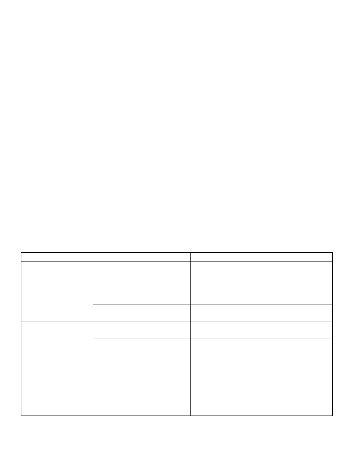
Electrode Diameter Electrode Grinding
(In.) Diameter (mm) Time
.040” 1.0mm 5-8 sec
1/16” 1.6mm 11-15 sec
3/32” 2.4mm 15-20 sec
1/8” 3.2mm 25-35 sec
5/32” 4.0mm 30-40 sec
3/16” 4.8mm 55-65 sec
Table 1: Recommended grinding times for each diameter.
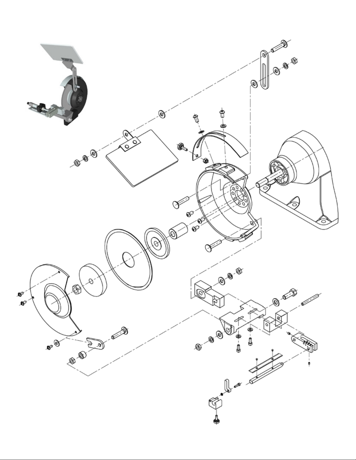
Consult Appendix A from Illustrated Parts
brochure and optional Accessories
Figure 1: Optimal location of electrode point contact area Figure 2: Electrode grinding assembly

Document: DGP-2 & DGP-2-V2 Tungsten Grinder Product User Manual | Released: 5/13, Rev. A
LEFT SIDE OF DGP-2 PRECISION TUNGSTEN GRINDER
Page 9

Document: DGP-2 & DGP-2-V2 Tungsten Grinder Product User Manual | Released: 5/13, Rev. A
Page 10
LEFT SIDE OF DGP-2 PRECISION TUNGSTEN GRINDER
ITEM PART NUMBER DESCRIPTION QTY
1 DGP-F010-A ARBOR SPACER 1
2 DGP-P307 BASE - ELECTRODE - LEFT SIDE - MOD FOR DGP-2 & -3 1
3 DGP-P310 BOLT - HEX HD - 3/8”-16 X 1 SST 2
4 W/GRINDER CARRIAGE BOLT 5/16-18 X 1-1/2 3
5 EYESHIELD BRACKET SET 4
6 EYESHIELD PLEXIGLAS 1
7 DGP-F120 SECONDARY SAFETY STRIP 1
8 DGP-F167-A HUB - INNER FOR DGP-2 AND 3 LEFT SIDE 1
9 DGP-F175-A HUB - OUTER FOR DGP-2 AND 3 LEFT SIDE 1
10 DGP-P460 KNOB - #10 SHEAR-LOC - 5/8 OD - BLACK 1
11 W/GRINDER LEFT WHEEL INSIDE COVER 1
12 W/GRINDER LEFT WHEEL OUTSIDE COVER 1
13 DGP-F232 NUT - HEX - 5/16-18 2
14 DGP-P494 NUT - HEX - LOCKING NYLON INSERT - #10-32 STL 2
15 DGP-F233 NUT - HEX 1/2-12 LH THREAD 1
16 DGP-PG1396 SCREW - BHC - 1/4-20 X 1/2 - ALLOY - BLACK 2
17 W/GRINDER SCREW - FLANGED - 1/4-20 X 1/2 3
18 W/GRINDER SCREW - PAN HEAD - #10-24 X 3/8 3
19 DGP-PG1397 SCREW - SHC - #10-32 X 5/8 SST 1
20 W/GRINDER SPACER - 5/16 ID X 19/32 OD X 3/8 1
21 DGP-F050 SUPPORT ARM - LEFT SIDE 1
22 W/GRINDER UPRIGHT BAR 1
23 W/GRINDER UPRIGHT BAR (CUT IN HALF) 1
24 DGP-P700 WASHER - FLAT - 1/4 ID X 1/2 OD X .05 SST 2
25 DGP-P705 WASHER - FLAT - 1/4 X 5/8 SST 1
26 DGP-P725 WASHER - FLAT - 3/8 1
27 W/GRINDER WASHER - FLAT 5/16 4
28 W/GRINDER WASHER - LOCK 5/16 3
29 W/GRINDER MOTOR SHAFT - LEFT SIDE 1
30 W/GRINDER MOTOR HOUSING - LEFT SIDE 1
31 DGP-P735 WHEEL - CUT-OFF 1
32 DGP-F040 BLOCK - DGP-2 CUT-OFF INDEXER 1
- DGP-F130 CUT-OFF FORK ASSY FOR DGP-2 1
33 - BAR - RULER SUPPORT 1
34 - CUT-OFF FORK 1
35 DGP-F190 PIVOT BLOCK FOR DGP-2 & -3 1
36 DGP-F205 PIVOT SHAFT FOR DGP-2 & -3 1
37 - SCREW - SET - #4-40 X 3/16 SST 1
38 DGP-F150 HANDLE - DGP-2 CUT OFF INDEXER 1
39 DGP-P450 KNURLED KNOB - #8 SHCS - 1/2 OD - BLACK 1
40 DGP-P520 SCALE - DGP-2 - INCH - SST FLEX (STANDARD) 1
DGP-P530 SCALE - DGP-2 - METRIC - SST FLEX (OPTIONAL) 1
41 DGP-P610 SCREW - FHS - #2-56 X 1/8 - SST 2
42 DGP-PG1387 SCREW - SHC - #10-32 X 1/2 - ALLOY - BLACK 2
43 DGP-P570 SCREW - SHC - #6-32 X 1/2 - ALLOY - BLACK 1
44 DGP-P570 SCREW - SHC - #8-32 X 1/2 - ALLOY - BLACK 1
45 DGP-P550 SCREW - SET - #8-32 X 3/16 - CUP POINT - ALLOY - BLACK 1
46 DGP-P723 WASHER - FLAT - #10 X 7/16 OD X .05 THK SST 2
47 DGP-PG1398 WASHER - SPLIT LOCK - #6 SST 1
48 DGP-PG1399 SCREW - SHC - 3/8-16 X 3/4 - ALLOY - BLACK 1
DGP-P662-A

Document: DGP-2 & DGP-2-V2 Tungsten Grinder Product User Manual | Released: 5/13, Rev. A
Page 11
RIGHT SIDE OF DGP-2 PRECISION TUNGSTEN GRINDER

Document: DGP-2 & DGP-2-V2 Tungsten Grinder Product User Manual | Released: 5/13, Rev. A
RIGHT SIDE OF DGP-2 PRECISION TUNGSTEN GRINDER
ITEM PART NUMBER DESCRIPTION QTY
1 DGP-F007 ANGLE POINTER 1
2 DGP-F025 ANGLE SCALE 1
3 DGP-F142 WHEEL ARBOR 1
4 DGP-P177 BOLT - HEX - 3/8” - 16 x 3/4” HEXBOLT HEAD 1
5 DGP-F060 COLLET - .040” (1.0mm)
DGP-F070 COLLET - 1/16” (1.6mm)
DGP-F080 COLLET - 3/32” (2.4mm)
DGP-F090 COLLET - 1/8” (3.2mm)
DGP-F100 COLLET - 5/32” (4.0mm)
DGP-F110 COLLET - 3/16” (4.8mm)
6 DGP-P662-A EYESHIELD BRACKET SET R/S 1
7 DGP-P663-A EYESHIELD PLEXIGLASS R/S 1
8 DGP-P410 HANDLE - ADJUSTABLE CLAMPING 3
9 DGP-P460 KNOB - #10 SHEAR-LOC - BLACK 1
10 DGP-P440 KNOB - #6 SHEAR-LOC - BLACK 1
11 DGP-P310 BOLT - HEX - 3/8” 16 X 1 1
12 DGP-F231 NUT - HEX 1/2”-12 RH THREAD 1
13 DGP-F200 PIVOT BUSHING (GRINDING) 10-32 1
14 DGP-F277 RIGHT WHEEL INSIDE COVER 1
15 DGP-F278 RIGHT WHEEL OUTSIDE COVER 1
16 DGP-F225 SCALE SUPPORT BAR 1
17 DGP-P661 SCREW - BHC - #10-32 X 1” - ALLOY - BLACK 2
18 DGP-P1442 SCREW - BHC - #10-32 X 1/2” - ALLOY - BLACK 4
19 DGP-P660 SCREW - BHC - #10-32 X 1-1/4” - ALLOY - BLACK 1
20 DGP-P541 SCREW - BHC - #6-32 X 1/4” - ALLOY - BLACK 1
21 DGP-P1320 SCREW - BHC - #6-32 X 3/8” - ALLOY - BLACK 1
22 DGP-P570 SCREW - BHC - #8-32 X 1/2” - ALLOY - BLACK 2
23 DGP-PG536 SCREW - FLANGED - 1/4”-20 X 1/2” 3
24 DGP-P178 SCREW - PAN HEAD - #10-24 X 3/8” 3
25 DGP-PG1439 SCREW - SET - 1/4”-20 X 3/8” - ALLOY - BLACK 2
26 DGP-PG1320 SCREW - SHC - #6-32 X 3/8” - ALLOY - BLACK 2
28 DGP-PG1363 SCREW - SHC - #10-32 X 1” - ALLOY - BLACK 1
29 DGP-P542 SCREW BHSCH BLK #8-32 X 1/2” 2
30 DGP-F230 SUPPORT BRACKET 1
31 DGP-F222 UPRIGHT BAR 1
32 DGP-P730 WASHER - FLAT - #10 X 1/2” OD X 3/32” 4
33 DGP-P725 WASHER - FLAT 3/8” 3
34 DGP-P724 WASHER - SPLIT LOCK 3/8” 2
35 DGP-PG1426 WHEEL - DIAMOND - 300 GRIT (STANDARD) 1
DGP-PG1425 WHEEL - DIAMOND - 600 GRIT (OPTIONAL) 1
36 DGP-F242 X-AXIS CLAMP BLOCK 1
37 DGP-F245 X-AXIS GUIDE BAR 1
38 DGP-F255 Y-AXIS CLAMP BLOCK 1
39 DGP-F260 Z-AXIS CLAMP BLOCK 1
40 DGP-F270 Z-AXIS GUIDE BRACKET 1
41 DGP-P400 GRINDER - BENCH 6” SINGLE PHASE 1/3 HP 1
42 DGP-F180-A BLOCK POINT FLAT DRESSER 1
43 DGP-P550 SCREW SET SHC CUP 1
44 DGP-P179 1/4”-20 X 3/8” KNOB 1
45 DGP-PG1334 1/4” WASHER FLAT SS 1
CHOICE
OF 4
Page 12

Document: DGP-2 & DGP-2-V2 Tungsten Grinder Product User Manual | Released: 5/13, Rev. A
Page 13
ACCESSORIES AND CONSUMABLES PARTS LIST
Description Part no.
300 Grit Grinding Wheel - For grinding .040” to 3/32” (1.0mm to 2.4mm) DGP-PG1425
600 Grit Grinding Wheel - For grinding 3/32” to 3/16” (2.4mm to 4.8mm) DGP-PG1426
Diamond Cutting Wheel DGP-P735
Vacuum Filters (Cartridge type for vacuum units only) DGP-M968
Upgrade to Vacuum System (Includes cabinet, vacuum system and exible spotlight) DGP-UPG
Carrying Case (For transporting stand-alone unit to site work.) DGP-P345
Flexible Spotlight (with bulb) DGP-P480
Replacement Bulb for Flexible Spotlight (110V / 220V version) DGP-P490
Tip/Flat Gauge (For measuring the diameter of the tip/at) DGP-F145
Replacement Collets: .040” (1.0mm) DGP-F060
1/16” (1.6mm) DGP-F070
3/32” (2.4mm) DGP-F080
1/8” (3.2mm) DGP-F090
5/32” (4.0mm) DGP-F100
3/16” (4.8mm) DGP-F110
Cabinet Only (no vacuum or exible spotlight) DGP-P330
Replacement Grinder Switch DGP-P667
Pin Vises: Small .040”-1/16” (1.0mm to 1.6mm) DGP-P513
Medium 1/16” to 1/8” (1.6mm to 3.2mm) DGP-P514
Large 1/8” to 3/16” (3.2mm to 4.8mm) DGP-P515
To order your replacement parts, or if we may assist you, please call us:
2651 Lavery Court • Newbury Park, CA 91320
Tel: 805.498.3837 • Fax: 805.498.9347
www.diamondground.com
This manual suits for next models
1
Table of contents
Other DGP Grinder manuals
Popular Grinder manuals by other brands

YATO
YATO YT-82104 instruction manual

Graphite
Graphite 59G110 instruction manual

EFA
EFA 53 Operating and maintenance instructions, Sparepart list

Scantool
Scantool 1220 instruction manual

EINHELL Expert
EINHELL Expert TE-AG 230 DP Original operating instructions

Würth
Würth KNS 150-E Translation of the original operating instructions