DGP 2 User manual

Document: DGP-M2 User Manual Rev: B
0
2/03
/2022
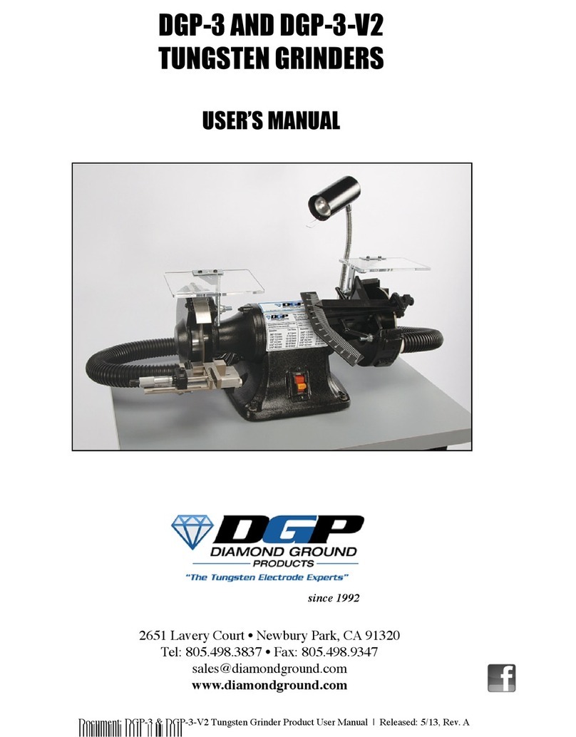
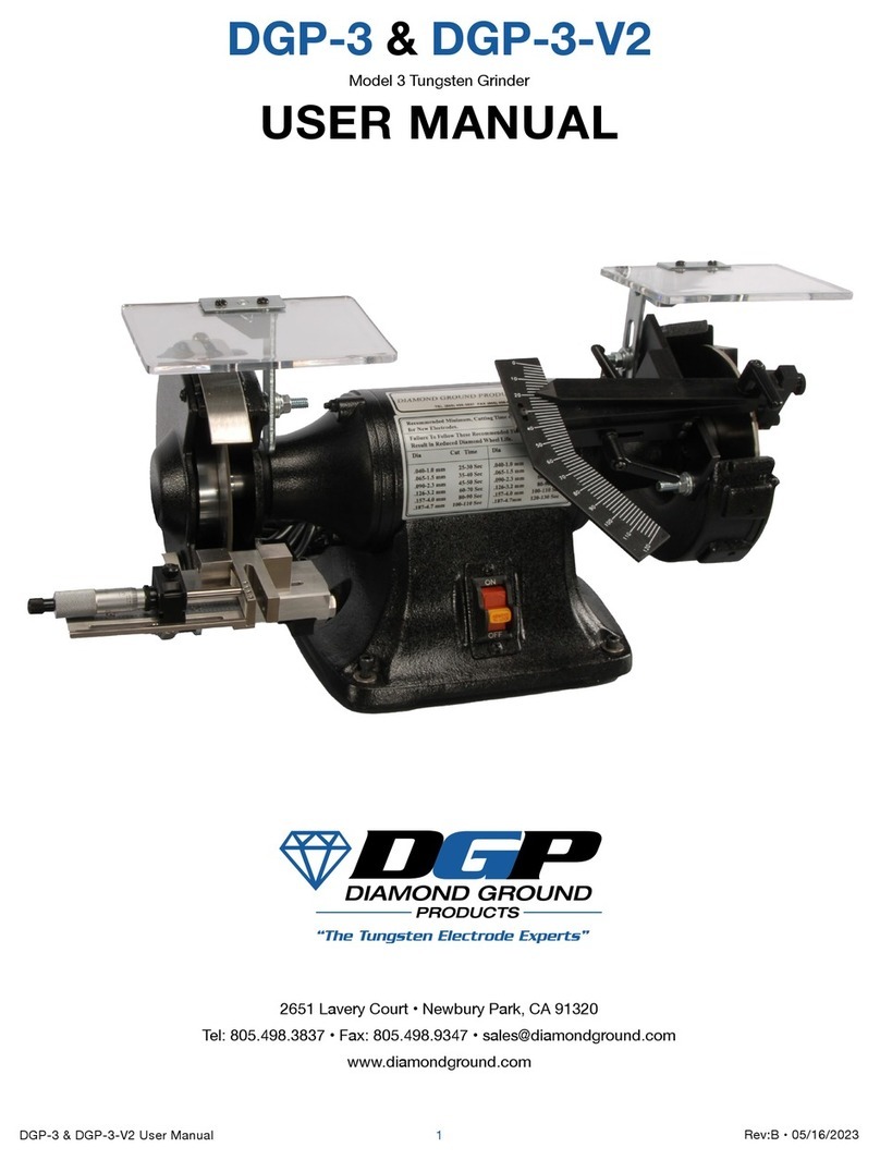
DGP-M2
AND DGP-M2-V2
MODEL 2
TUNGSTEN GRINDER
(Formerly
known as DGP-2)
USER MANUAL


Document: DGP-M2 User Manual Rev: B
0
2
/
03
/2022
TABLE OF CONTENTS
General Page
General Description 3
Vacuum System Overview 3
Specifications 3
Unpacking 4
Warranty Information 4
Safety and Operating Guidelines 4
Maintenance 5
Troubleshooting Chart 5
Mounting the DGP-M2 6
Using the Equipment
Electrode Grinding Assembly 6
The Basics 6
Operating Instructions 6
Recommended grinding times 7
Electrode Cutting Assembly 7
The Basics 7
Operating Instructions 8
Other Information
Exploded Views - Left & Right Sides 9,11
Parts Lists - Left & Right Sides 10,12
Accessories and Consumable Parts List 13
DGP-M2
& DGP-M2-V2
MODEL 2
TUNGSTEN GRINDER
(Formerly known as DGP-2)
USER MANUAL
Page 2

Document: DGP-M2 User Manual Rev: B
0
2/03
/2022
Models DGP-M2
and DGP-M2-V2
1. GENERAL DESCRIPTION
DGP-M2
Tungsten Welding Electrode Grinder is designed specifically for the longitudinal grinding of the conical or
tapered points on tungsten welding electrodes from .040’’ (1.0mm) to 3/16’’ (4.8mm) in diameter.
This model also cuts
these electrodes to
precise lengths using a
precision scale
and
an adjustable indexer block. The grinder is equipped with
a completely enclosed ball bearing motor and a rotor and shaft assembly that is dynamically balanced for vibration-free
rotation.
The
motor
housing
is
compact
and
the
unit
has
ample
side
clearance
on
the
grinding
and
cutting
wheels.
Wheel guards are secured to the shaft by threaded nuts and safety eyeshields are also included.
DGP-M2
and DGP-M2-V2 Tungsten Electrode Grinders offer precise grinding for your precision welding needs. The
DGP-M2
consists of a horizontal axis grinder that can be pedestal mounted, a diamond grinding wheel and assembly on
the
right
side,
and
a
diamond cutting
wheel
for
cutting
an
electrode
to
a
precision
length
on the left side.
The
DGP-M2-V2 adds
a
foam-insulated cabinet,
vacuum system for dust collection,
and a flexible spotlight in addition to
the
DGP-M2
features.
The DGP-M2
can be upgraded later to a DGP-M2-V2.
The
diamond
grinding
wheel
on
both
grinders
is
on
the
right
side
of
the
machine
and
the
surface
rotates
toward
the
electrode
which
provides
consistent
and
repeatable
points
from
each
grind.
The
grinding
surface
faces
right
and
the
right wheel enclosure housing supports the electrode grinding assembly in addition to a Point Flat Dresser
Block. The
location of the area of contact between the diamond grinding wheel and the tungsten electrode is
visible to the operator
at all times, which allows for excellent control of the grinding operation. After repeated use,
a groove will eventually
be
worn
into
the
wheel
at
the
contact
point.
The
contact
point
should
then
be
adjusted
downward
slightly
to
the
next
unused spot on the diamond grinding wheel. The
cutting
assembly on the left
side also provides excellent visibility and
is easy to operate.
Wheel rotation, viewed from the left end of the grinder, is
clockwise.
VACUUM SYSTEM OVERVIEW
The
DGP-M2-V2
comes
with
a
tool
cabinet
and
integrated
vacuum
system
for
the
collection
of
tungsten
dust.
This
feature
has
become
very
popular
due
to
notifications
in
the
past
few
years
about
the
danger
of
inhaling
dust
from
the
commonly
used
2%
Thoriated
tungsten,
which
is
a
known
radioactive
cancer-causing
element.
Please
contact
your
local
OSHA
office
if
you
would
like
more
information
about
this
issue.
In
addition,
we
offer
free
samples
of
non-radioactive
alternative
tungsten,
which
performs
better
in
most
applications.
Users
of
the
DGP-M2
can
later upgrade their systems to add the vacuum system if
c
hosen
later
.
It
is
impossible
to
contain
all
of
the
lightweight
dust
particles
that
deflect
quickly
off
the
wheels
from
grinding.
The vacuum system offers
a
way
of
collecting
the
majority
of
the
dust
that
is
produced
while
grinding
tungsten
electrodes.
Each
side
of the grinder
has
vacuum
holes
and
hoses
to
collect
dust.
To
maximize
the
suction
power,
use
the
valves
at
the
back
of
the
grinder
motor
to
direct
the
suction
to
the
side
you
are
using.
If
you
are
using
both
sides
at
the
same
time,
leave
both
sides
open.
However,
if
you
are
only
using
one
side,
close
the
valve
on
the
opposite
side
and
you will increase the suction power to the side you are using.
Replacement vacuum filters are in
stock
at the factory for immediate shipment.
2. SPECIFICATIONS
Motor:
1 HP 110/120 Volt, 60 Hz Standard OR 220/240 Volt, 50 Hz Optional
Wheels:
Right side:
Nickel Plated Diamond Wheel, 6’’ diameter
Left side:
Diamond Cutting Wheel, 6’’ diameter
Weight: DGP-M2:
42 lbs. / 19.05 kg in box
DGP-M2-V2:
152 lbs. / 68.9 kg on pallet
Page 3

Document: DGP-M2 User Manual Rev: B
0
2/03
/2022
3. UNPACKING
Check for shipping damage. Diamond Ground Products takes great pride in producing quality equipment. If for
some reason you find anything to be defective, please call us at: (805) 498-3837 and we will work with you to
solve the problem. The following accessories are shipped with the DGP-M2
and DGP-M2-V2 grinders:
1.
Pin Vise used to hold tungsten while grinding.
2.
Six different Hex Keys, used to make various adjustments, and one Hex Screwdriver, used to secure the
tungsten in the cutting apparatus.
3.
Collets (four of your choice)
-
used to guide the tungsten and hold it at the proper angle while grinding.
4. WARRANTY
The DGP-M2
& DGP-M2-V2 comes with a one-year warranty on parts and labor, excluding wheels that are a
consumable part that naturally wears over time. This warranty excludes abuse to the machine, dropping of the unit or
improper handling by the operator.
5. SAFETY AND OPERATING GUIDELINES
Before any work is done, read the caution below carefully. Working safely prevents accidents.
• When not in use, turn the grinder off for safety purposes and to decrease wear on the machine.
• Wear proper apparel. Do not wear loose clothing, including gloves, neckties, rings, bracelets, or other
jewelry, which
may get caught, in moving parts of the machine.
• Wear protective hair covering to contain long hair.
• Wear safety glasses and a facemask.
• Never operate power tools when tired, intoxicated, or when taking medication that may cause drowsiness.
• Work area should have sufficient lighting.
• A proper electrical outlet should be available for the tools. A three-prong plug should be plugged directly into
a three-
prong outlet. Extension cord should be the correct gauge.
• Keep visitors at a safe distance from work area.
• Always unplug grinder prior to inspection.
• Read this manual thoroughly for specific adjustments and operating procedures.
• Do not perform “make-shift” repairs. Any part that is damaged should be promptly replaced.
• Only use the
grinder for its intended purpose. Do not use it for a job it was not designed for.
• Make sure that the grinder is off before plugging it in.
• Do not apply extreme force on the tungsten while grinding. This may cause your grinder to jam or cause premature
grinding wheel wear.
• Never leave the grinder unattended. Turn the grinder off first and do not leave it until it comes to a complete stop.
• Know your grinder; learn its operation, applications, and specific limitations.
• Always unplug grinder prior to inspection.
• Read this manual thoroughly for specific adjustments and operating procedures.
• Grinding parts other than tungsten will severely decrease wheel and equipment life.
• Unplug the grinder when changing accessories, such as collets, wheel, or other replacement parts.
• Avoid accidental start-up. Make sure that the grinder is in the off position before plugging it in.
• Do not force the grinder. It will work most efficiently at the rate for which it was designed. Consult the
“Recommended
Minimum Cutting and Grinding Time for New Electrodes” sticker on the grinder to determine
optimum rate of speed.
• Use recommended accessories. Use of improper accessories may cause risk of injury of persons or accelerated wear
on
the grinder.
• Handle the tungsten and grinder correctly. Consult grinder operation procedures in this manual and handle tungsten
with pin vise whenever possible to protect hands from possible injury.
• Feed tungsten into grinding wheel against the direction of rotation of the wheel.
Page 4

Document: DGP-M2 User Manual Rev: B
0
2/03
/2022
SAFETY AND OPERATING GUIDELINES
(continued)
• Turn the wheel off if it jams. A wheel jams when it digs too deeply into the tungsten (the motor force keeps it stuck in
the tungsten).
• Never stand or lean on the grinder. Serious injury could occur if the grinder is tipped or if the cutting tool is
unintentionally contacted.
• Keep hands away from moving parts and cutting surfaces.
6.
MAINTENANCE
• Always unplug grinder before inspection.
• Keep the grinder clean for safest operation
• Remove adjusting keys and wrenches. Form a habit of checking that keys and adjusting wrenches are removed
before the grinder is turned on.
• Keep all safety guards in place and in good working order.
• Keep all parts in working
order. Check to determine that the guard or other parts will operate properly and
perform their intended functions.
• Check for damaged parts and alignment of moving parts, binding of moving parts, breakage of mounting parts
and any other condition that may affect the grinders operation. Consult DGP factory for replacement parts
at: (805) 498-3837
• Do not use power tools in dangerous environments, such as damp or wet locations. Do not expose power tools
to rain.
• Work area should be properly lighted.
• The proper electrical outlet should be available for the tool. For 110V, a three prong plug should be plugged
directly into a three prong outlet and /or extension cord.
• Keep visitors a safe distance from work area and keep children out of work place. Use padlocks or master switches to
prevent any unintentional use of power tools.
TROUBLESHOOTING CHART
SYMPTOMS POSSIBLE CAUSES(S) CORRECTIVE ACTION
Grinder won’t start 1. Blown line or tripped circuit
breaker
1. If fuse is blown, replace with fuse of proper
size. If breaker is tripped, reset it.
2. Low line voltage
2. If voltage is less than rated, check size of
wiring from main switch on property. If OK,
contact power company.
3. Material wedged between
wheel and guard
3. Remove material wedged between wheel
and guard
Excessive vibration 1. Improper mounting of grinder 1. Remount
or accessories
2. Improper wheel mounting
2. Remove both wheels then remount wheels
but rotate one wheel 1/4 turn with respect to its
previous position. The other wheel would
retain its original position.
Grooved wheel 1. Electrode pushed with 1. Use recommended grinding times table
excessive force
2. On steep angled tungsten,
collet touching wheel
2. Use short collets available from Diamond
Ground Products
Motor is overheating 1. Motor not turning freely
(without power)
1. Clean around wheels & shaft. Then replace
bearings.
Page 5

Document: DGP-M2 User Manual Rev: B
0
2/03
/2022
MOUNTING THE DGP-M2
The DGP-M2 stand alone grinder (without vacuum system and cabinet) should be mounted to a solid horizontal surface
(mounting hardware is not provided).
If mounted to a metal cabinet or pedestal, align the mounting holes with the corresponding holes in the cabinet or
pedestal. Insert a 1/4”-20 X 1 1/4’’ hex head bolt with flat washer beneath the head of the grinder. From the bottom of
the cabinet or pedestal, place a 1/4’’ flat washer and 1/4”-20 hex nut onto the bolt extension. Tighten only until the
space between the grinder base and the cabinet or pedestal is 1/8’’. Using a second nut on each bolt, tighten against the
first to prevent loosening by vibration.
If mounted to a wooden bench top, use 1/4’’ wood screws that are 1-1/4’’ long with flat washer beneath the heads.
Tighten screws until the space between the grinder base and the bench is 1/8’’.
Electrode Grinding Assembly
The Basics
The Electrode Grinding Assembly is attached to the right wheel housing (refer to Figure 1 on the next page for the
general arrangement of the assembly). It provides the means to support an electrode in a fixed position relative to the
diamond-grinding surface through an electrode guide collet that matches the electrode diameter. The electrode is
brought into gentle contact with the diamond-grinding surface and at the same time is rotated slowly in one direction
between the operator’s thumb and forefinger. As an alternative, pin vises are also provided to hold the tungsten during
rotation.
Operating Instructions
Note: all positioning and adjustment should be made before turning on the grinder.
Refer to Figure 2 on the next page for use with the following operation instructions:
1. If the tungsten you are using is already flat at the end, like new tungsten straight out of the box, proceed to Step 4.
2. Locate the Point Flat Dresser Block (DGP-PG1477) attached at the 6 o’clock position of the right side wheel cover.
Find the hole that matches the diameter of your tungsten and turn on the grinder. Slowly push the tip against the wheel
until the point is removed. Once again, be patient and do not gouge the wheel. A burr can form if too much pressure is
exerted on the tungsten.
3. Select the electrode guide collet with the hole diameter closest to the tungsten electrode diameter and position it in
the electrode guide collet tube. Notice that the collet has been beveled on a 15° angle at the front or exit end of the
collet. With this surface parallel to the grinding wheel surface, tighten the set screw to hold it in place. The back, or
entrance, end of this collet has been milled down to its center line to make it easy to insert the electrode for grinding.
4. Adjust the angular position of the electrode grinder assembly to the desired included angle of grind for the electrode
point using the angle adjustment handle (Handle A).
5. Left to right positioning: Adjust the position of the electrode grinder assembly using the horizontal adjustment knob
(Handle B) to place beveled surface of the electrode guide collet approximately 1/64” from the grinding surface.
6. Slip a tungsten electrode into and through the electrode guide collet to determine where it will contact the grinding
disk surface.
7. Up and down positioning: Adjust the electrode grinder assembly using the vertical adjustment knob (Knob C) so that
the tungsten electrode will contact the actual grinding surface.
Page 6

Document: DGP-M2 User Manual Rev: B
0
2/03
/2022
ELECTRODE GRINDING ASSEMBLY (continued)
8. Remove the tungsten electrode from the electrode
guide collet.
9. Put the eyeshield in place and start the grinder.
Slide the tungsten electrode into and through the
electrode guide collet and twirl the electrode (or the
pin vise holding the electrode) slowly in one direction
between thumb and forefinger as it approaches and
makes contact with the grinding surface. To retain
maximum symmetry of the point, try to keep from
moving the electrode side to side within the collet. The
best technique for this is to constantly lean the
electrode against the inside surface of the collet while
turning. Continue grinding until the desired sharpness
is obtained. Make sure to continue rotation as the
electrode is backed off from the wheel or a flat spot
may occur along the point. Contamination of the
wheels can occur by using the diamond grinding and
cutting wheels as all-purpose shop wheels. If you
grind tools or other metal items, other than electrodes,
there is always the risk of contaminating the wheels.
Table 1: Recommended grinding times for each diameter.
Electrode Cutting Assembly
The Basics
The left side of the DGP-M2 is an Electrode Cutting Assembly which includes a Diamond Cutting Wheel and cutting
apparatus consisting of a
measuring ruler on a cut-off arm
, a cut-off fork, and an adjustable indexer for cutting the
electrodes to various lengths quickly and accurately. Holes are provided for several different diameters of electrodes in
the cut-off fork. The cutting assembly rotates from a level position up towards and past the edge of the cutting wheel to
accomplish the cut. Please refer to Figures 3 and 4 on Page 8 in conjunction with the following instructions.
Electrode Diameter
(in.)
Electrode Diameter
(mm)
Grinding Time
(sec)
.040” 1.0mm 5-8 sec
1/16” 1.6mm 11-15 sec
3/32” 2.4mm 15-20 sec
1/8” 3.2mm 25-35 sec
5/32” 4.0mm 30-40 sec
3/16” 4.8mm 55-65 sec
Page 7

Document: DGP-M2 User Manual Rev: B
02/03
/2022
ELECTRODE CUTTING ASSEMBLY (continued)
Operating Instructions
1. Locate the adjustable Cutoff Indexer Block (A), which is the black anodized block mounted on the Ruler Support
Bar (C). Make sure the Cutoff Indexer Handle (F) is positioned so that it is in contact with the steel Ruler (G).
2. The exciting feature of the Cutoff Indexer System is the ability to change between different lengths quickly and
accurately. To locate the Cutoff Indexer Block (A), loosen Thumb Screw (B) and position the Cutoff Indexer Block
(A) to achieve the required length then finger tighten the Thumb Screw (B).
3. With your length chosen and the power off, insert the electrode tip first, into and through (right to left) the
appropriate sized hole on the Cut-Off Fork (D) until tip gently touches the right side of the Cutoff Indexer Handle (F).
4. Tighten the associated setscrew (E) on the Cut-Off Fork (D) with the provided hex screwdriver to hold the electrode
securely. Then turn on the power.
5. Pivot the cutting assembly up and towards the diamond cutting wheel and gently push the electrode shaft into the
cutting wheel. For larger electrode sizes, please be especially patient.
6. Return the cutting assembly to the level position before removing the electrode.
Figure 3: Electrode Cutting Assembly Figure 4: Electrode Cutting Assembly
Viewed from the left Viewed from the right
Consult Illustrated Parts Lists on the following pages
and
See Page 13 for optional Accessories and Consumables Parts List
Page 8

23 26
28
27
12
14
15
16
17
18
19
20
21
24 25
30
31
32
33
29
7
6
5
3
8
5
9
10
4
2
11
13
1
22
DGP
-
M
2 PRECISION TUNGSTEN GRINDER
LEFT SIDE
Page 9
Document: DGP-
M2
User Manual Rev: B
02/03
/202
2

DG
M
GGD
D
02/03/
2
Pe
e
Document DGP-
M
e nu
P DSP
DGP-P-
DGP-P-
GD- P - SDD
GD- P - P
DGP-P- SD PGSS D
DGP-
-A
SD D
DGP-P GD D
DGP-P
-A
SP S
DGP-
F
-
-
DGP-P DD G
DGP-- -
DGP- D
DGP- SD D
DGP-PG S SSS - P
DGP-- SS SD
DGP-P S SSS SS - P P
DGP-P S S
DGP-P
DGP-P
S- SDD
SS P
DGP-- SPP
DGP-PG S
-
SS
3/8"
DGP- D D
DGP-P S SP SS
DGP- D
DGP-P S S - -
DGP-P S D -
DGP-
-A
SPP
DGP-P S
DGP-P S D
DGP-P S - S
DGP-P S S - P -
DGP-P S D SS
DGP-- S D
DGP-P S
3/8"
DGP-P S
-
S D
1
DGP- P
DGP- P S

1
2
3 4 6 8 9 10 11 1275
13
5
14
15
16
17
19
18
20
21
30
28
26
32
33
31
34
35
36
37
24
33
44
33
39
38
32
40
25
23
22
41
42
43
29
27
32
DGP-
M2
PRECISION TUNGSTEN GRINDER
RIGHT SIDE
Page 11
Document: DGP-
M2
User Manual
Rev: B
02/03/2022

DGP-
M2
PRECISION TUNGSTEN GRINDER
RIGHT SIDE
Document: DGP-
M2
User Manual Rev: B
02/03/2022
ITEM PART NUMBER DESCRIPTION QTY
DGP-P400-A BENCH GRINDER-MOTOR 7” 1HP 120V - STANDARD
1
DGP-P400-B BENCH GRINDER-MOTOR 7” 1 HP 220V - OPTIONAL 1
2
DGP-P605-A
DGP-P609-A
ON-OFF SWITCH
(STANDARD)
110V
ON-OFF SWITCH
(OPTIONAL)
220V
1
3 DGP-F277-A RIGHT WHEEL INSIDE COVER W/HARDWARE 1
4 DGP-P602-A WHEEL GUARD W/HARDWARE 1
5 DGP-P67
3
-A ARBOR SPACER W/WASHER 1
6 DGP-PG1439 SCREW – SHSS ¼”- 20 x 3/8” CUP PT BLK 1
7 DGP-F155-A ARBOR 1
DGP-PG1425 WHEEL – DIAMOND 300 GRIT (STANDARD)
8
DGP-PG1426 WHEEL – DIAMOND 600 GRIT (OPTIONAL) 1
9 DGP-PG1442 SCREW – BHSCS #10-32 x ½” BLK 4
10 DGP-PG1349 SCREW – BHSCS #6-32 x ¼” BLK 4
11 DGP-F278-A RIGHT WHEEL OUTSIDE COVER W/HARDWA
R
E 1
12 DGP-PG1477 BLOCK - FLATTING 1
13 DGP-F231 NUT – ½” 12 HEX-RH THREAD 1
14 DGP-P660 SCREW – BHSCS #10-32 x1 ¼” BLK 2
15 DGP-P730 WASHER – BLK FLAT #10 x ½” OD x 3/32” THK 5
16 DGP-F220-A INSIDE DUST SHIELD 1
17 DGP-PG1458 PLUG FINISHING ½” SNAP BLK 1
18 DGP-P672 SCREW – SHC #10-32 x 5/8” BLK 1
19 DGP-F230-A SUPPORT BRACKET 1
20 DGP-P725 WASHER - FLAT 3/8” 1
21 DGP-P310 BOLT – HEX HEAD 3/8” 16 x 1 1
22 DGP-F255-A Y AXIS CLAMP BLOCK 1
23 DGP-P660 SCREW – BHSCS #10-32 x 1 ¼” BLK 2
24 DGP-P661 SCREW – BHSCS #10-32 x 1 BLK 2
25 DGP-F049 COLLET - .020”
DGP-F060 COLLET - .040”
RIGHT DGP-F070 COLLET – 1/16”
HAND DGP-F080 COLLET – 3/32”
DGP-F090 COLLET – 1/8”
DGP-F100 COLLET – 5/32” ID ¼” OD
DGP-F110 COLLET – 3/16”
CHOICE
OF 4
TOTAL
26 DGP-P440 KNOB - #6 BLK 1
27 DGP-PG1320 SCREW
–
BHSCS #6-32 x 3/8” BLK 1
28 DGP-P460 KNOB - #10 BLK 1
29 DGP-PG1363 SCREW – SHCS #10-32 x 1” BLK 1
30 DGP-F260 Z AXIS CLAMP BLOCK 1
31 DGP-F007-A ANGLE POINTER 1
32 DGP-P730 WASHER
–
FLAT #
1
0 x ½” OD x 3/32” 4
33 DGP-P410 HANDLE – ADJUSTABLE THREADED HOLE - BLK 3
34 DGP-P541 SCREW – BHSCS #6-32 x 3/8” BLK 1
35 DGP-F025-A ANGLE SCALE – RT HAND 1
36 DGP-P571 SCREW – BHC #8-32 x ½” BLK 2
37 DGP-F225-A SCALE SUPPORT BAR 1
38 DGP-
F
242-A X AXIS CLAMP BLOCK 1
39 DGP-F245-A X AXIS GUIDE BAR 1
40 DGP-P542 SCREW – BHSCH #8-32 x ½” BLK 2
41 DGP-P177 BOLT – HEX 3/8” 16 x ¾” ZINC 1
42 DGP-P604 WASHER – FLAT 5/16” x 1/8” - STEEL 1
43 DGP-P733 WASHER – LOCK 5/16” 1
44 DGP-P663-R EYE SHIELD – PLEXIGLASS W/HARDWARE 1
Page 12

Document: DGP-M2 User Manual Rev: B
0
2/03
/2022
ACCESSORIES AND CONSUMABLES PARTS LIST
Description Part No.
300 Grit Grinding Wheel - For grinding .040” to 3/32” (1.0mm to 2.4mm) DGP-PG1425
600 Grit Grinding Wheel - For grinding 3/32” to 3/16” (2.4mm to 4.8mm) DGP-PG1426
Cutting Wheel DGP-P735
Vacuum Filters (Cartridge type for vacuum units only) DGP-M968
Upgrade to Vacuum System (Includes cabinet, vacuum system and flexible spotlight) DGP-UPG
Flexible Spotlight (No bulb) DGP-P490
Replacement Bulb for Flexible Spotlight (110V / 220V version) DGP-P480
Tip/Flat Gauge (For measuring the diameter of the tip/flat) DGP-F145
Replacement Collets .040” (1.0mm) DGP-F060
1/16” (1.6mm) DGP-F070
3/32” (2.4mm) DGP-F080
1/8” (3.2mm) DGP-F090
5/32” (4.0mm) DGP-F100
3/16” (4.8mm) DGP-F110
Cabinet Only (no vacuum or flexible spotlight) DGP-P685
110 V (Standard) DGP-P605-A
Replacement Grinder Switch
220 V (Optional) DGP-P609-A
Small .040”-1/16” (1.0mm to 1.6mm) DGP-P513
Medium 1/16” to 1/8” (1.6mm to 3.2mm) DGP-P514
Pin Vises
Large 1/8” to 3/16” (3.2mm to 4.8mm) DGP-P515
To order your replacement parts, or if we may assist you, please call us:
2651 Lavery Court • Newbury Park, CA 91320
Tel: 805.498.3837 • Fax: 805.498.9347
www.diamondground.com
Page 13

2651 Lavery Court Newbury Park, CA 91320
Phone: (805) 498-3837 Fax: (805) 498-9347
E-mail: [email protected] Website: www.diamondground.com
TRI-MIX- WS2
Non-Radioactive – Color Code: Cream / Turquoise
Tri-Mix™ tungsten is non-radioactive tungsten with the similar performance to 2% Thoriated
tungsten. Three Oxides scientifically balanced promote migration and evaporation rates that
result in extended tungsten life. This tungsten offers stability and consistency not seen on most
other tungsten. Results commonly received in some applications include an increase in the
quality of welds, a dramatic increase in service life as well as, an increase in arc starts before
resharpening and fewer misfires saving the customer money and time.
CRYO-T
Radioactive – Color Code: Pink
Cryogenically treated thoriated tungsten which provides a more dense structure of the thoriated
blend. Easier starting as compared to 2% Thoriated. Performance includes easier arc starts as
well as extended tungsten life.
2% THORIATED & 4% THORIATED
Radioactive element – Color Code: Red / Orange
2% Thoriated material is the primary tungsten used in the United States. Used primarily for
DC Welding, it has a low work function and provides high load and amperage capability.
Vapors, grinding dust and disposal of thorium dioxide raise health, safety and environmental
concerns.
1.5% LANTHANATED & 2% LANTHANATED
Non-Radioactive – Color Code: Gold / Blue
The most commonly used, non-radioactive tungsten used as an alternative to 2% Thoriated
tungsten. 2% Lanthanated offers a long electrode life under heavy or pulsing amperage loads.
Common results include, improved and stable arc starts at any amperage level, good resistance
to contamination and long service life. Because of its high ability to resist thermal shock, the
user receives excellent ignition with a lower burn-off rate.
2% CERIATED
Non-Radioactive – Color Code: Grey / Formerly Orange
Recommended for short welding cycles on low-amp, DC orbital tube, pipe, thin sheet, and
small part applications. Provides low current capacity and arc ignition with good arc stability.
Ceriated tungsten is not recommended for higher applications, because the oxides contained in
ceriated material tend to migrate very quickly to the heat at the tip of the electrode.
ZIRCONIATED
Non-Radioactive – Color Code: Brown / White
Recommended for use in radiographic-quality welding, where tungsten contamination must be
minimized. Zirconiated material tends to ball-up easily in AC applications. Performance
includes good arc starting and current capacity. Not recommended for DC Welding.
PURE TUNGSTEN
Non-Radioactive – Color Code: Green
Non-Radioactive with a low current capacity. Recommended for use in AC welding of
aluminum.

This manual suits for next models
2
Table of contents
Other DGP Grinder manuals

