Dhollandia DH-VO Series User manual

Doc: USE_VO_VB_VX_US_EN_2020_rev0 Rev: 0Date: JANUARY 1, 2020
Manufacturer:
DHOLLANDIA US, L.L.C.
270 Southridge Parkway
Bessemer City North Carolina, 28016
website : www.dhollandia.com
DH-VO, VB, VX multi-deck liftgates
OPERATION MANUAL
Read the manual in its entirety before operating the liftgate
Keep this manual in the vehicle cab, as reference for the driver and liftgate operator

1
DHOLLANDIA
TABLE OF CONTENTS
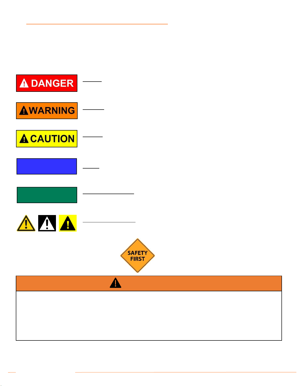
1UNDERSTANDING SAFETY AND WARNING SIGNS........................................................................................................................ 3
2CONTACT INFORMATION AND DISCLAIMERS................................................................................................................................ 4
3GENERAL INTRODUCTION ............................................................................................................................................................... 5
4INTENDED USE .................................................................................................................................................................................. 5
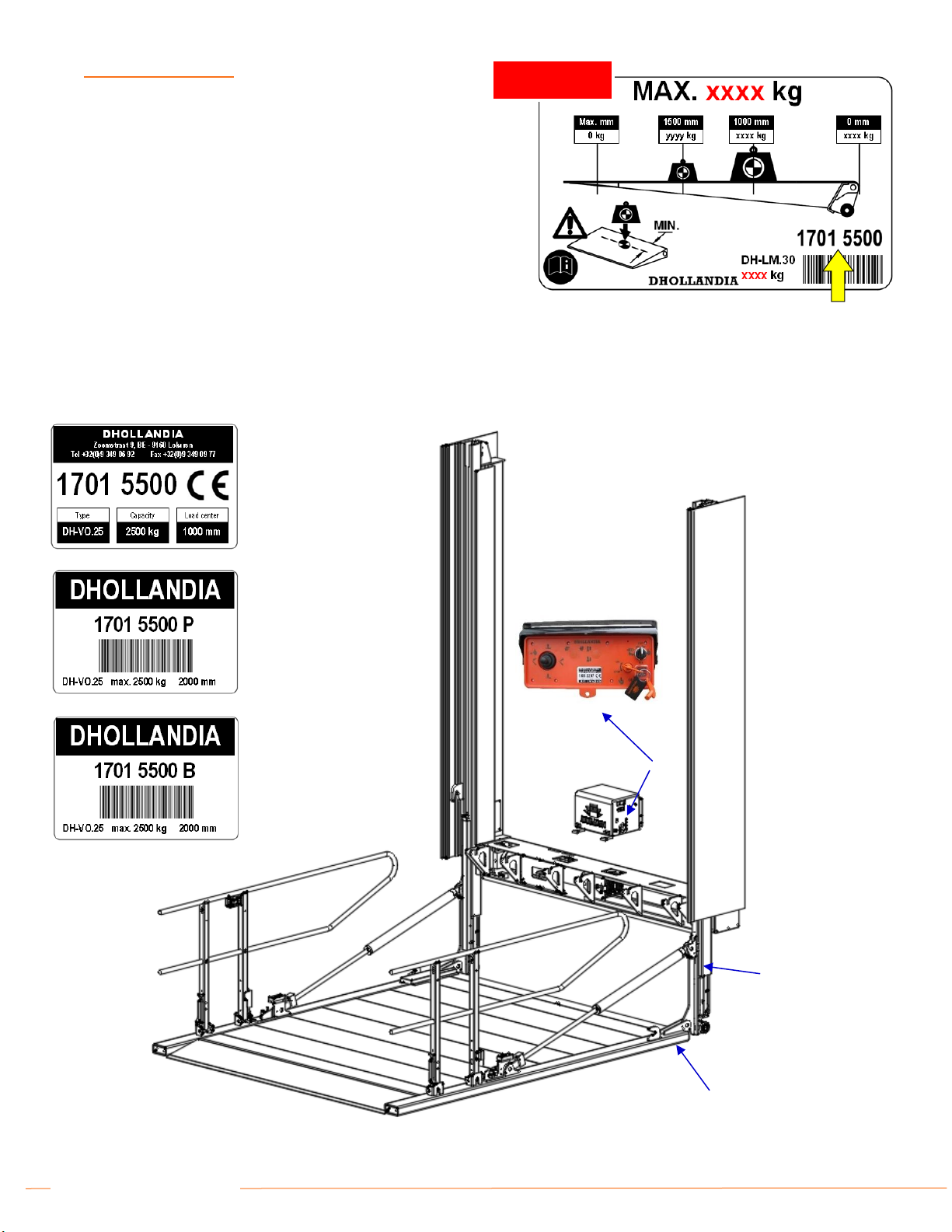
5IDENTIFICATION ................................................................................................................................................................................ 6
6DESCRIPTION AND LIFTGATE TERMINOLOGY .............................................................................................................................. 7
6.1 General ....................................................................................................................................................................................... 7
7SAFETY INSTRUCTIONS FOR USING THE LIFTGATE.................................................................................................................. 18
7.1 DO NOT use liftgate without adequate safety and operator training......................................................................................... 18
7.2 General safety instructions........................................................................................................................................................ 18
7.3 Danger zones, risk of crush and shear injury............................................................................................................................ 23
7.4 Additional risks of lifting above the vehicle floor level................................................................................................................ 26
7.4.1 Risk of falling ........................................................................................................................................................................ 26
7.4.2 Risk of other persons standing under the platform ............................................................................................................... 27
7.4.3 Risk of crushing and shearing............................................................................................................................................... 28
7.4.4 At the vehicle roof................................................................................................................................................................. 30
7.4.5 Special attention for overhead cross tube between the lift runners ...................................................................................... 30
7.5 Safe operator position ............................................................................................................................................................... 31
7.6 Instructions for working at loading docks .................................................................................................................................. 34
7.7 Recommended daily pre-trip inspection.................................................................................................................................... 37
7.8 Importance of preventative maintenance .................................................................................................................................. 39
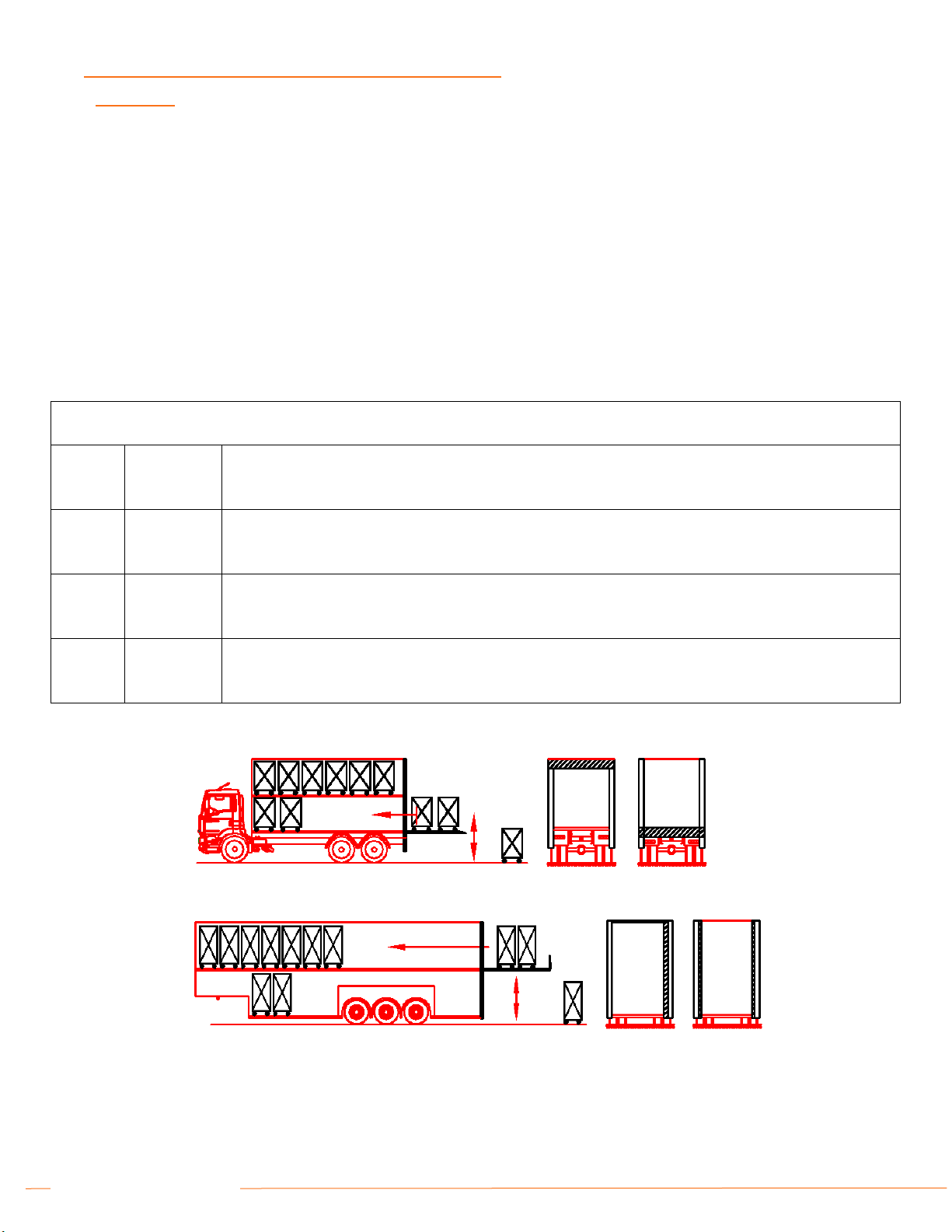
8LOAD CHARTS AND CORRECT LOADING PROCEDURES........................................................................................................... 40
9OPERATING INSTRUCTIONS –PRINCIPLES AND PROCEDURES.............................................................................................. 43
9.1 Platform ride.............................................................................................................................................................................. 43
9.2 Main external control boxes ...................................................................................................................................................... 44
9.3 Auxiliary controls....................................................................................................................................................................... 47
9.4 Switching the main power ON / OFF......................................................................................................................................... 49
9.5 Operation of the standard multi-deck column lift with hydraulic closure.................................................................................... 50
9.6 Operation of the internal column lift without tilt cylinders........................................................................................................... 53
9.7 Operation of the DH-VOH.D4 removal lift ................................................................................................................................. 56
9.8 The use of stabilizing legs......................................................................................................................................................... 61
9.9The use of cart stops................................................................................................................................................................. 62
10 DECALS............................................................................................................................................................................................. 65
10.1 Regular decals .......................................................................................................................................................................... 65
10.2 Use of the ‘WARNING. LIFTGATE OUT OF SERVICE. DO NOT ATTEMPT TO OPERATE’ sign .......................................... 69
11 MEANING OF SAFETY AND WARNING SIGNS .............................................................................................................................. 70
12 END NOTE ........................................................................................................................................................................................ 72

2
DHOLLANDIA

3
DHOLLANDIA
1UNDERSTANDING SAFETY AND WARNING SIGNS
Many safety signs and symbols used in this manual are based on international standards, others refer to specific situations or actions.
Consult section 11 for an overview of signs and symbols used in DHOLLANDIA manuals and their meanings.
Please take special notice of the following signs used in the manual. They indicate the likelihood and severity of a potential injury if a
person fails to follow the instructions presented on the safety sign.
WARNING
Failure to understand and follow the instructions in this manual can put the operator and any bystanders at great risk of serious
bodily injury and death.
Prior to operating the liftgate, make sure you understand the safety and warning signs used, and read them in conjunction with
the instructions in this manual.
If in doubt, DO NOT operate the liftgate. Contact your national DHOLLANDIA distributor. See page 4 for contact info.
NOTICE
DANGER: indicates an imminently hazardous situation which, if not avoided, will result in death or
serious injury. [white letters on red background]
WARNING: indicates a potentially hazardous situation which, if not avoided, could result in death
or serious injury. [black letters on orange background]
CAUTION: indicates a potentially hazardous situation which, if not avoided, could result in minor
or moderate injury. [black letters on yellow background]
NOTICE: is used to address practices not related to physical injury. [white letters on blue
background]
SAFETY INSTRUCTIONS: indicate general instructions relative to safe work practices, reminders
of proper safety procedures, or the location of safety equipment. [white letters on green
background]
SAFETY
INSTRUCTIONS
SAFETY ALERT SYMBOL: is used to alert the user to potential hazards. All safety messages that
accompany this sign shall be obeyed to avoid possible harm. [free-standing, or on back-ground
colours red, orange, yellow or black]

4
DHOLLANDIA
2CONTACT INFORMATION AND DISCLAIMERS
DHOLLANDIA liftgates are regularly being adapted to new vehicle and chassis developments and specialized customer requirements.
Therefore, DHOLLANDIA reserves the right to alter product specifications without prior notice; and potentially modifications or new
developments might not have been taken into account at the time of printing.
NOTICE
Please confirm you have reviewed the most up-to-date version of this manual prior to operation of the associated DHOLLANDIA liftgate.
See below for instructions to download the latest version of the manual.
Contact your national DHOLLANDIA distributor if you have any questions regarding the installation, operation, repair and maintenance
of DHOLLANDIA liftgates, to obtain replacement copies of manuals or decals, or to learn about available equipment options for
DHOLLANDIA liftgates.
Take notice of following important disclaimers:
DISCLAIMERS
DHOLLANDIA disclaims liability for any personal injury, death, or property damage that results from operating a liftgate that has
been modified from the original design, without explicit written approval from the manufacturer.
DHOLLANDIA disclaims liability for any personal injury, death, or property damage that results from use of aftermarket or non-
OEM replacement parts for service or repair of the liftgate.
DHOLLANDIA disclaims liability for any personal injury, death, or property damage that results from improper use of the liftgate.
DHOLLANDIA disclaims liability for any personal injury, death, or property damage that results from overloading or improperly
loading the platform, disregard of the maximum rated lift capacity and the applicable load charts.
There are no warranties, express or implied, including the warranty of merchantability or a warranty of fitness for a particular
purpose extending beyond that set forth in this manual.
The latest version of all manuals can also be downloaded from the DHOLLANDIA website
www.dhollandia.com → Downloads → User’s manuals → … select required manual
DHOLLANDIA US, LLC
United States - East
200 Hilton Street West
Easton PA 18042
Tel: 855-894-1188
Sales.USA@dhollandia.com
DHOLLANDIA CANADA, Inc.
Canada
2105 Boulevard des Entreprises
Terrebonne Quebec J6Y1W9
Tel: 888-750-5438
Sales.CANADA@dhollandia.com
DHOLLANDIA MEXICO, Inc.
Mexico
Fraccionamiento Industrial
Dinamo del Norte,
Calle Tierra 103-105
C.P. 65500, Salinas Victoria,
Monterrey- Nuevo Leon
Tel: +52 81 13340968
Sales.MEXICO@dhollandia.com
DHOLLANDIA US, LLC
United States - West
12968 Santa Ana Avenue
Fontana CA 92337
Tel: 855-856-8225
Sales.USA@dhollandia.com

5
DHOLLANDIA
3GENERAL INTRODUCTION
This OPERATION MANUAL explains how the DHOLLANDIA liftgate is manufactured, what safety devices are incorporated in its
design; and how to use the liftgate in a correct manner, that preserves the integrity of the machine over the intended lifetime and helps
maximize the safety of the operator and any bystanders.
The MAINTENANCE AND REPAIR MANUAL (separate) explains how to maintain and service the liftgate in the appropriate manner,
maximizing the safety of the operator and any bystanders, and ensuring the reliability of the liftgate over the intended lifetime.
The CE IDENTIFICATION AND INSPECTION BOOK (separate) contains the serial number identification, the CE Declaration of
Conformity, the Fitting Declaration to be filled out by the installer of the liftgate, and an overview of the owner’s legal obligations in
terms of periodic testing and certification.
The manuals must be kept with the liftgate at all times, as a reference book for the operators and technical service
4INTENDED USE
DHOLLANDIA liftgates are designed to be fitted to commercial vehicles (commercial trucks, trailers and semi-trailers), and shall be used
exclusively to load and unload the goods transported on the vehicle it is fitted to, within the limits of the load chart, in compliance with the
operator instructions and safety instructions described in this manual.
WARNING
Improper use of the liftgate will put the operator and other parties at great risk of serious bodily injury and death. Therefore, the use
of the liftgate is restricted to skilled operators only; who have been properly trained, and who know and understand the full contents
of this manual.
Unauthorized modifications to the liftgate can put the operator and other parties at great risk of serious bodily injury and death.
Therefore, it is strictly forbidden to modify the liftgate and its safety devices in any way.
Use of aftermarket or non-OEM replacement parts to repair or maintain the liftgate is strictly prohibited and may result in serious
bodily injury or death to the operator or any bystanders.
WARNING
Improper use of the liftgate will put the operator and bystanders at great risk of serious bodily injury and death. Therefore, it is
strictly forbidden to use the liftgate in a different way, or for different purposes than described in the operation manual.
The liftgate must NEVER be used as an elevated work platform, to push loads, or to carry people.
The liftgate must NEVER be used as a wheelchair lift.
DHOLLANDIA disclaims liability for any personal injury and / or property damage that results from improper use.

6
DHOLLANDIA
5IDENTIFICATION
Every DHOLLANDIA liftgate is identified by and labelled with a
unique 8-digit serial number (with or without a space between the
first and last 4 digits). Use this number for any inquiry on a particular
liftgate, or when ordering replacement parts.
In addition to the liftgate type and serial number, the various serial
number labels provide additional information, such as: the maximum
rated lift capacity and load chart, the bumper certification number,
the date of manufacture, etc...
These labels are usually affixed to the vehicle body and various
liftgate components, and can be found in following locations (the
yellow arrows point to the serial numbers):
❶
❷
❸
EXAMPL
E
Affixed to the side of the vehicle body, or on the platform
❶
❷
❸
Image shows model DH-VO

7
DHOLLANDIA
6DESCRIPTION AND LIFTGATE TERMINOLOGY
6.1 GENERAL
DHOLLANDIA liftgates are developed and manufactured using state-of-the-art technology, high quality materials and components,
and highly skilled workmanship. They comply with the European CE safety regulations mentioned in the Declaration of Conformity
issued with each lift (unless agreed otherwise for liftgates exported outside of CE region).
The range of multi-deck column lifts DH-V* comprises of a wide variety of constructions with different lifting mechanisms, but share
main components such as the platform and its safety features, cart-stop and ramp options, safety devices etc.
These column lifts are designed for a wide variety of trucks, trailers and semi-trailers, and offer lift capacities of 1650lb to 8800lb.
When considering the drive mechanism of the various lifts, the following types can be distinguished between:
Fig. nr
Type
Description
1
DH-VB*
Overhead beam lift: operated by a single lift cylinder mounted in a beam at the vehicle roof level and a set
of steel ropes and pulleys
2
DH-VO*
Lower beam lift: operated by a single lift cylinder mounted in a beam at, or below the vehicle floor level and
a set of steel ropes and pulleys, or heavy-duty chains and chain wheels
3
DH-VX*
Operated by a single lift cylinder mounted in vertically positioned cylinder beam integrated in the right side
column, and a set of steel cables and pulleys
4
DH-VH*
Operated by 2 hydraulic lift cylinders mounted in the left and right side columns. No cables or chains
involved.

8
DHOLLANDIA
When considering where the platform operates, the following types can be distinguished between:
Fig. nr
Type
Description
5
External lift
In its travel position, the platform is stowed vertically behind the vehicle body. Before use, the platform
is lowered approx. 10 cm, then tilted open 90 degrees from the vertical travel position, to a horizontal
work position.
The external lift has the 4 functions: OPEN - LOWER - LIFT - CLOSE
Usually the opening and closing of the platform is driven by 2 hydraulic tilt cylinders. But depending on
options chose, manual closing or hydraulic closure by 1 hydraulic tilt cylinder (without adjustable platform
orientation) are also available.
6
Internal lift
Lifting platform or “moving deck” travelling UP - DOWN between 2 or more decks inside the vehicle
body.
Usually the internal lift has no tilt cylinders, no adjustable platform orientation.
Main details and terminology: see next pages
NOTICE
The range of multi-deck column lifts DH-V* comprises of a wide variety of lifts with an even wider variety of options, which cannot
all be covered within the scope of this generic operation manual.
The images in the next pages are therefore only examples of popular execution, but might differ from the column lift actually
delivered to you.
Even if details in the execution of your lift are not reflected in this manual, the general safety precautions and operation instructions
apply, and must be observed prior to and during operation.
WARNING
If in doubt on any liftgate related issue, ALWAYS contact your local DHOLLANDIA distributor for help or advice, prior to continuing.
❺
❺
❻

9
DHOLLANDIA
DH-VO/VB/VX CABLE OR CHAIN DRIVEN LIFT ● HYDRAULIC CLOSURE ● LIFTGATE TERMINOLOGY
See figure below for parts corresponding to the numbers in this table
#
Description
1
Lift columns L+R: set of 2 columns mounted in a fixed position against the vehicle body. They form the rails in which the lift
runners carrying the platform travel up and down.
2
Cylinder beam: horizontal or vertical beam mounted at various positions. Check the difference between DH-VO, VB and VX
above . This beam contains the lift cylinder, the drive system consisting of steel ropes and pulleys.
1+2
Lift frame: the lift columns + cylinder beam together form the lift frame.
3
Lift cylinder: usually 1 hydraulic cylinder used to LOWER / LIFT the lift runners, the platform and its load.
4
Drive system: set of steel ropes and pulleys, or chains and chain wheels, used to transfer the movement induced by the lift
cylinder to the lift runners and the platform. The drive system usually contains multiple tiers, so that the stroke of the cylinder
can result in a multiplied vertical travel of the lift runners and the platform.
5
Platform: carries the load during lifting and lowering. Usually manufactured from a steel frame with aluminium infill profiles with
a non-slip working surface, although full aluminium or feel steel platforms are also available. In standard execution, the platform
is equipped with a fixed leading edge. Optional cart-stops or a retention ramp at the outboard platform edge, are available as
an option.
6
Lift runners L+R: set of 2 slides carrying the platform, travelling up and down in the lift columns. They are lifted and lowered
by the lift cylinder and the drive system.
7
Stow lock L+R: set of hooks mounted on the left and right side of the platform, keeping it in its travel position while not being
used, and pressing it against the sealing rubbers (if so equipped) to form the rear closure of the vehicle body.
8
Guard rails L+R: rails to protect the operator against falling from heights, and incurring serious personal injuries. They should
be used on all exposed platform sides. The liftgate standard EN1756-1 makes them compulsory for all lifting heights above 2m.
9
Auxiliary controls: LIFT / LOWER controls integrated in one of the guard rails
10
Toe-guard flap: hinged flap + detection switch stopping the LIFT function when a person steps on it, or load stands on it. It
aims at protecting the toes and feet of the operator in the dangerous crushing zone between the moving platform and the
loading floors of the vehicle.
11
Tilt cylinders L+R: usually 2 hydraulic cylinders used on external lifts to OPEN / CLOSE the platform, or to change its angle
when opened in work position. Depending on options chose, manual closing or hydraulic closure by 1 hydraulic tilt cylinder
(without adjustable platform orientation) are also available.
12
Side shrouds and seals L+R: set of panels and sealing rubbers mounted on the left and right side columns of external lifts,
used to seal the platform against the columns, and protect the cargo from rain. The shrouds can be original DHOLLANDIA
parts, or be designed and manufactured by the body builder.
13
Hydraulic pump unit: contains the electric motor driving the hydraulic pump, the oil tank, and the control valves. The unit is
mounted separately on the vehicle chassis.

10
DHOLLANDIA
14
Main external control box: mounted in a fixed position at the side of the vehicle or under the body. It contains the switches to
OPEN - LOWER - LIFT - CLOSE the platform.
DH-VO LOWER BEAM COLUMN LIFT ● HYDRAULIC CLOSURE
INBOARD platform edge
EXAMPL
E
1,
12
2
3
4
5
6
7
7
14
10
1
12
4
4
6
8
8
9
11
11
13
7

11
DHOLLANDIA
DH-VB OVERHEAD BEAM COLUMN LIFT ● HYDRAULIC CLOSURE
INBOARD platform edge
OUTBOARD platform edge
1, 12
2
3
4
5
6
7
7
14
10
1
12
4
4
6
8
8
9
11
11
13
7
EXAMPL
E

12
DHOLLANDIA
DH-VX SIDE BEAM COLUMN LIFT ● HYDRAULIC CLOSURE
1, 12
2, 3
4
5
6
7
7
14
10
1
12
4
4
6
8
8
9
11
11
13
7

13
DHOLLANDIA
DH-VH FULLY HYDRAULIC EXTERNAL COLUMN LIFT ● HYDRAULIC CLOSURE ● LIFTGATE TERMINOLOGY
See figure below for parts corresponding to the numbers in this table
#
Description
1
Lift columns L+R: set of 2 columns mounted in a fixed position against the vehicle body. They form the rails in which the lift
runners carrying the platform travel up and down.
2a
Overhead cross member: cross member of the lift frame located just below the vehicle roof.
2b
Floor cross member: cross member of the lift frame located just below the vehicle roof level.
1+2
Lift frame: the lift columns + overhead and floor cross members together form the lift frame.
3
Lift cylinders L+R: 2 hydraulic cylinders mounted in the lift columns, used to LOWER / LIFT the lift runners, the platform and
its load.
4
Platform: carries the load during lifting and lowering. Usually manufactured from a steel frame with aluminium infill profiles with
a non-slip working surface. In standard execution, the platform is equipped with a fixed leading edge. Optional cart-stops or a
retention ramp at the outboard platform edge, are available as an option.
5
Lift runners L+R: set of 2 slides carrying the platform, travelling up and down in the lift columns. They are lifted and lowered
by the 2 lift cylinders mounted in the lift columns.
6
Stow lock L+R: set of hooks mounted on the left and right side of the platform, keeping it in its travel position while not being
used, and pressing it against the sealing rubbers (if so equipped) to form the rear closure of the vehicle body.
7
Hydraulic retention ramp: optional full-width load restraint flap, operated by a hydraulic cylinder in the platform and the electric
controls of the lift (9 or 13). When travelling up and down, the ramp can be raised in vertical position to prevent carts and
wheeled objects from accidentally falling off the platform. At the ground, the ramp can be deployed as an access ramp to drive
cargo on and off the platform.
8
Guard rails L+R: rails to protect the operator against falling from heights, and incurring serious personal injuries. They should
be used on all exposed platform sides. The liftgate standard EN1756-1 makes them compulsory for all lifting heights above 2m.
9
Auxiliary controls: LIFT / LOWER controls integrated in one of the guard rails. If an optional hydraulic ramp is mounted (see
n° 7), additional controls are mounted on the guard rails to RAMP UP / RAMP DOWN.
10
NOTICE
Although the side loading ramps can be blocked in vertical position as guard rails for the operator on the platform, they are
NOT designed to function as heavy-duty load-restraints and to sustain frequent, hard impact by means of carts or pallets
run into them.
Side loading ramps: optional combination of guard rails and side loading ramps. In travel position, these ramps are folded
down on the platform surface. When raised and blocked in vertical position, they function as guard rails (see n°8). When opened
up to the side, they function as side ramp for loading or unloading cargo to the kerb.
11
Tilt cylinders L+R: usually 2 hydraulic cylinders used on external lifts to OPEN / CLOSE the platform, or to change its angle
when opened in work position.

14
DHOLLANDIA
DH-VH FULLY HYDRAULIC EXTERNAL COLUMN LIFT ● HYDRAULIC CLOSURE
12
Hydraulic pump unit: contains the electric motor driving the hydraulic pump, the oil tank, and the control valves. The unit is
mounted separately on the vehicle chassis.
13
Main external control box: mounted in a fixed position at the side of the vehicle or under the body. It contains the switches to
OPEN - LOWER - LIFT - CLOSE the platform. In case an optional hydraulic retention ramp is mounted, the control box also
incorporates the functions RAMP UP / RAMP DOWN.
INBOARD platform edge
OUTBOARD platform edge
1
2a
4
6
7
13
10
1
5
8
8
9
11
11
12
3
2b
3
5
6
9
10

15
DHOLLANDIA
DH-VH FULLY HYDRAULIC EXTERNAL COLUMN LIFT + INTERNAL PLATFORM ● HYDRAULIC CLOSURE
See figure below for parts corresponding to the numbers in this table
#
Description
1
Lift columns L+R: set of 2 columns mounted in a fixed position against the vehicle body. They form the rails in which the lift
runners carrying the platform travel up and down.
2a
Overhead cross member: cross member of the lift frame located just below the vehicle roof.
2b
Floor cross member: cross member of the lift frame located just below the vehicle roof level.
1+2
Lift frame: the lift columns + overhead and floor cross members together form the lift frame.
3
Lift cylinders L+R: 2 hydraulic cylinders mounted in the lift columns, used to LOWER / LIFT the lift runners, the platform and
its load.
4a
External platform: raised and lowered by the L+R lift cylinders and carries the load during lifting and lowering. Usually
manufactured from a steel frame with aluminium infill profiles with a non-slip working surface. In standard execution, the platform
is equipped with a fixed leading edge. Optional cart-stops or a retention ramp at the outboard platform edge, are available as
an option.
4b
Internal “slave” platform: internally mounted section of the platform that can also carry load during lifting and lowering. It is
called “slave” platform, because it has no own lift system to travel up and down independently from the external platform: it can
travel up / down when linked to the external platform, or stay parked at the upper or lower deck when disconnected from it. The
locking device used to park the internal platform at the second deck is provided by the vehicle manufacturer.
5
Lift runners L+R: set of 2 slides carrying the platform, travelling up and down in the lift columns. They are lifted and lowered
by the 2 lift cylinders mounted in the lift columns.
6
Stow lock L+R: often, rear swing doors behind the external platform are used to form the rear closure of vehicle body. Hence,
depending on execution, this type of external platform might not be equipped with stow locks as shown in item 6 on previous
page.
7
Hydraulic retention ramp: optional full-width load restraint flap, operated by a hydraulic cylinder in the platform and the electric
controls of the lift (9 or 13). When travelling up and down, the ramp can be raised in vertical position to prevent carts and
wheeled objects from accidentally falling off the platform. At the ground, the ramp can be deployed as an access ramp to drive
cargo on and off the platform.
8
Guard rails L+R: rails to protect the operator against falling from heights, and incurring serious personal injuries. They should
be used on all exposed platform sides. The liftgate standard EN1756-1 makes them compulsory for all lifting heights above 2m.
9
Auxiliary controls: LIFT / LOWER controls integrated in one of the guard rails. If an optional hydraulic ramp is mounted (see
n° 7), additional controls are mounted on the guard rails to RAMP UP / RAMP DOWN.
10
Tilt cylinders L+R: usually 2 hydraulic cylinders used on external lifts to OPEN / CLOSE the platform, or to change its angle
when opened in work position.
11
Hydraulic pump unit: contains the electric motor driving the hydraulic pump, the oil tank, and the control valves. The unit is
mounted separately on the vehicle chassis.

16
DHOLLANDIA
12
Main external control box: mounted in a fixed position at the side of the vehicle or under the body. It contains the switches to
OPEN - LOWER - LIFT - CLOSE the platform. In case an optional hydraulic retention ramp is mounted, the control box also
incorporates the functions RAMP UP / RAMP DOWN.
DH-VH FULLY HYDRAULIC EXTERNAL COLUMN LIFT + INTERNAL PLATFORM ● HYDRAULIC CLOSURE
OUTBOARD platform edge
INBOARD platform edge
1
2a
4a
7
12
1
8
8
10
11
3,
5
2b
3,5
9
4b
10

17
DHOLLANDIA
LOAD RESTRAINTS ● LIFTGATE TERMINOLOGY
See figure below page for parts corresponding to numbers in this table
#
Description
1
Platform: carries the load during lifting and lowering. Manufactured from steel or light-weight aluminium and with a non-slip
working surface. In standard execution, the platform is equipped with a fixed leading edge. Optional cart-stops in the platform
surface, or a retention ramp at the outboard platform edge, are available as an option.
2
Cart-stops: usually 2 load restraint flaps mounted in or just in front of the fixed leading edge of the platform. Depending on
options chosen, the cart-stops feature a manual or an automatic operation (see also §9.9 from page 65 onwards) and are actuated
by springs.
3
Rear or outboard retention ramps : 1 full-width or 2 partial width load restraints ramps mounted at the outboard platform edge.
In travel position, the ramps lie folded back on the platform surface. When travelling up and down, the ramps can be raised and
blocked in vertical position to prevent rolling cargo on the platform from falling off. At the ground, the ramps can be deployed as
an access ramp to drive cargo on and off the platform. (See also 9.9 from page 61 onwards).
4
Side retention ramps : 2 load restraints ramps mounted at the side edges of the platform. In travel position, the ramps lie folded
back on the platform surface. When travelling up and down, the ramps can be raised and blocked in vertical position to prevent
rolling cargo on the platform from falling off. At the ground, the ramps can be deployed as an access ramp to drive cargo on and
off the platform. (See also 9.9 from page 61 onwards)
See previous page for the optional hydraulic retention ramp (n° 7).
1
2
1
3
4
4

18
DHOLLANDIA
7SAFETY INSTRUCTIONS FOR USING THE LIFTGATE
7.1 DO NOT USE LIFTGATE WITHOUT ADEQUATE SAFETY AND OPERATOR TRAINING
DHOLLANDIA liftgates shall be exclusively used to load and unload the goods transported on the carrying vehicle, within the limits of
the applicable load chart, in compliance with the operator instructions and safety instructions in this manual.
The operator should follow all other policies and procedures applicable to the job situation including health & safety regulations, road
and traffic regulations, as well as company procedures. The operator should not use the liftgate if he/she cannot use it in accordance
with all applicable regulations and instructions.
The operator must be at least 18 years of age.
7.2 GENERAL SAFETY INSTRUCTIONS
WARNING
Improper use of the liftgate will put the operator and other parties at great risk of serious bodily injury and death.
To reduce the risk of serious bodily injury to the operator and any bystanders, the use of the liftgate is restricted to skilled operators,
who have been properly trained, and who know and understand the full contents of this manual.
To reduce the risk of serious bodily injury or death, THE OPERATOR MUST COMPLY WITH ALL SAFETY INSTRUCTIONS AND
WARNING LABELS IN THIS SECTION AND THE ENTIRE MANUAL before and while operating the liftgate.
WARNING
To avoid serious bodily injury or death, the operator must use appropriate work clothes. NEVER wear loose-fitting clothes that
may be trapped in the moving parts of the liftgate. ALWAYS wear professional safety-toe shoes, protective gloves, and eye
protection. Use of hardhat is recommended.
Slipping (and falling) can result in serious bodily injury and death. To prevent injury by slipping:
oALWAYS wear professional safety-toe shoes with a good non-slip sole.
oDO NOT use the liftgate if it is covered with snow, mud, dirt, debris, liquids or other substances.
oDO NOT run on the platform.
Tripping (and falling) can result in serious bodily injury and death. To prevent injury by tripping:
oDO NOT use liftgate platform as a step. NEVER leave the liftgate unattended in partially deployed position.
oPay attention to protruding items on the platform surface at all times (ex. platform lights, cart-stops and their
levers, foreign objects, etc…).
oDO NOT run on the platform.
Falling from the platform can result in serious bodily injury and death. To prevent injury by falling:
oMake sure your footing is solid and you maintain 3 points of contact. See 7.5 on page 30.
oUse safety rails where available. See 7.5 on page 30.
oNEVER move the vehicle while a person is standing on the platform or inside the vehicle body.
oNEVER use the platform as an elevated working platform.

19
DHOLLANDIA
WARNING
Prior to operating the liftgate, the vehicle must be safely parked on level and solid ground, the parking brake applied, and the
engine must be switched off. Lock open the rear doors and secure all other moving parts of the vehicle body. Failure to abide by
these instructions can result in serious bodily injury or death to the operator or bystanders.
Ensure that the vehicle cannot tip-over when putting heavy weight on the platform. If the vehicle or the liftgate are equipped with
mechanical or hydraulic stabilizing legs, deploy these before opening the platform. Ensure that the stabilizing legs are positioned
on solid even ground. In case of soft terrain (sand, gravel,…), solid support blocks must be used under the stabilizing legs. Failure
to abide by these instructions can result in serious bodily injury or death to the operator or bystanders.
To reduce the risk of serious bodily injury or death which may
result from other vehicles when parked, ALWAYS make sure a
safety distance of 16 ft. or 5 m. is kept between the back of the
truck and the following vehicle.
To reduce the risk of serious bodily injury or death, ALWAYS
make sure the platform is clearly visible to other persons from
all approach directions. DHOLLANDIA recommends the use of
4 warning cones, placed around the work area of the platform.
[See notice below].
To reduce the risk of serious bodily injury or death, make sure
the working zone is sufficiently lighted.
NOTICE
DHOLLANDIA offers optional platform mounted flashing lights and flags to make the platform more visible to other people. Please visit
www.dhollandia.com or contact the national DHOLLANDIA distributor for more information. See page 4 for contact info.
Other manuals for DH-VO Series
1
This manual suits for next models
2
Table of contents
Other Dhollandia Automobile Accessories manuals