Dhollandia DH-RK 33 User manual

Order ref : xxx Doc: FIT_US installation manual RK_US EN_2023 Rev: 0Date: APRIL 12, 2023
DH-RK 33 / 44 / 55
INSTALLATION MANUAL
Read the manual in its entirety before operating the liftgate
Keep this manual in the vehicle cab, as reference for the driver and liftgate operator
Manufacturer:
DHOLLANDIA US, L.L.C.
270 Southridge Parkway
Bessemer City North Carolina, 28016
website : www.dhollandia.com

1
DHOLLANDIA
TABLE OF CONTENTS
1UNDERSTANDING SAFETY AND WARNING SIGNS...................................................................................................................... 3
2INTRODUCTION, CONTACT INFO AND DISCLAIMERS................................................................................................................. 4
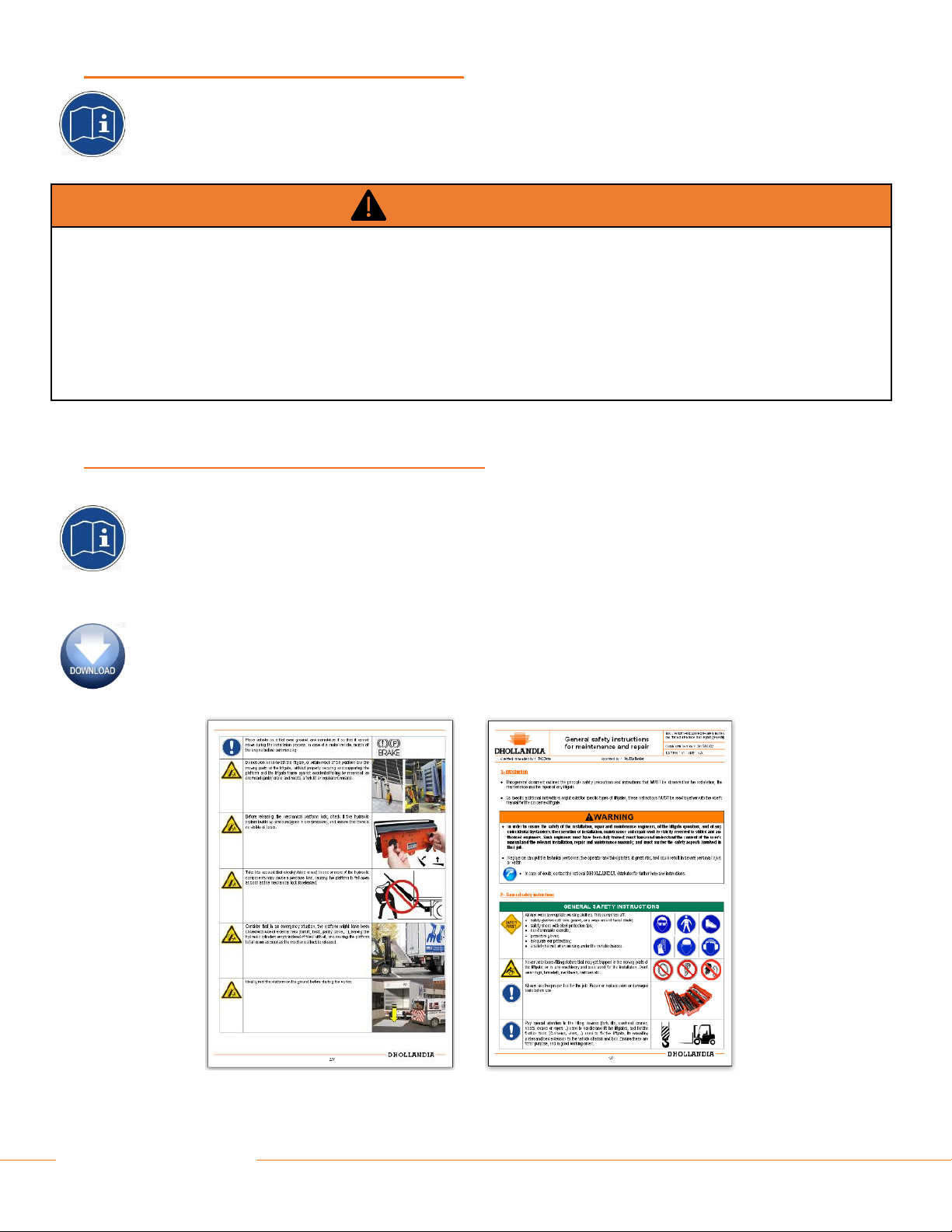
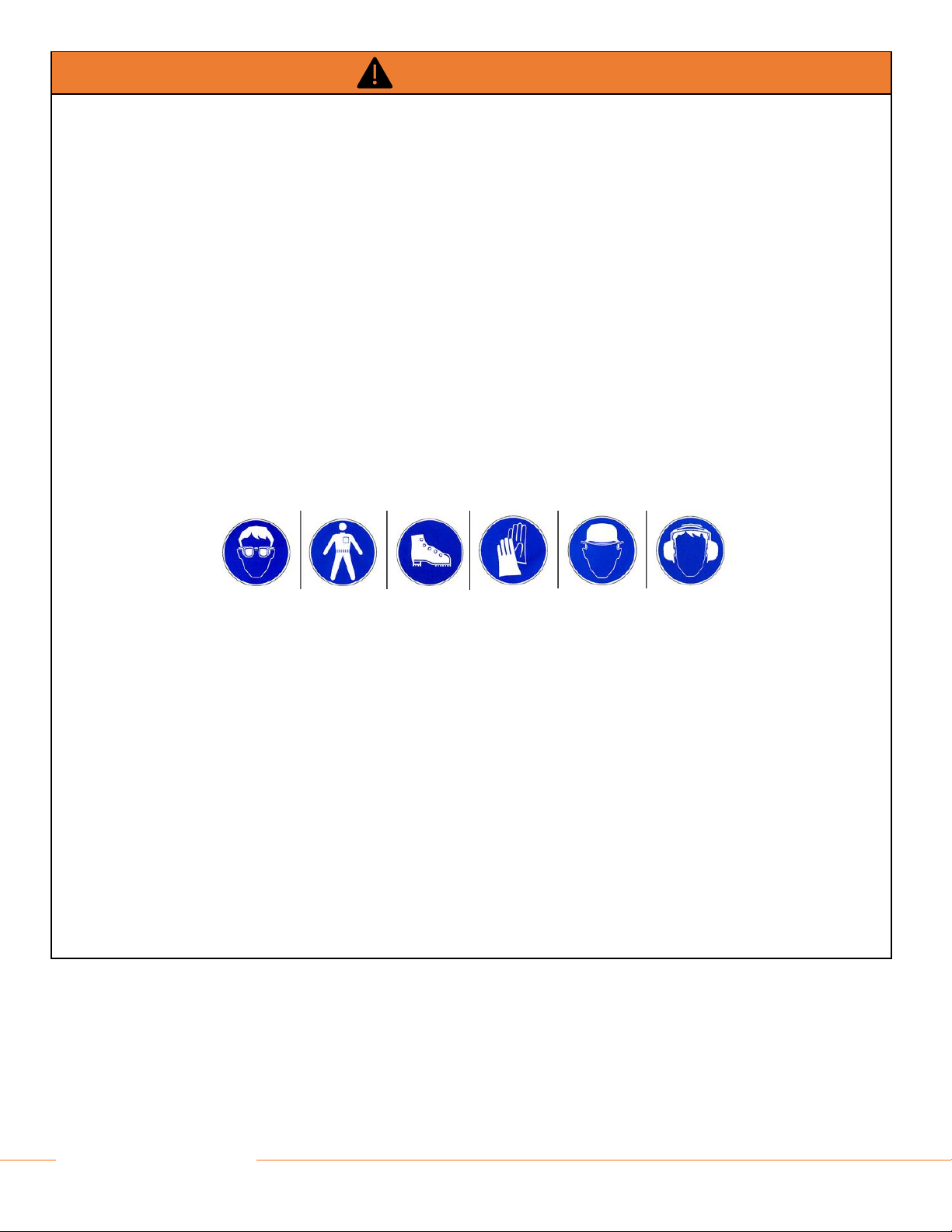
3SAFETY PRECAUTIONS FOR OPERATION ................................................................................................................................... 6
4SAFETY PRECAUTIONS FOR INSTALLATION............................................................................................................................... 6
5LIFTGATE TERMINOLOGY .............................................................................................................................................................. 8
5.1 DH-RPL liftgate terminology...................................................................................................................................................... 8
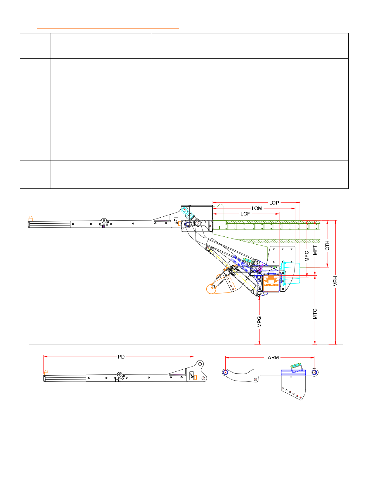
5.2 Installation parameters terminology .......................................................................................................................................... 9
5.3 Getting started......................................................................................................................................................................... 11
6INSTALLATION DIMENSIONS AND GUIDELINES ........................................................................................................................ 12
6.1 Installation dimensions............................................................................................................................................................ 12
6.2 Installation resources .............................................................................................................................................................. 13
7BED EXTENSION AND CHASSIS CUT .......................................................................................................................................... 14
7.1 Rear sill cut ............................................................................................................................................................................. 15
8MOUNTING OF THE BED EXTENSION ......................................................................................................................................... 16
9MOUNTING OF THE LIFT FRAME (PREMOUNTED PLATFORM)................................................................................................ 18
10 FIXATION OF THE MOUNT PLATES ............................................................................................................................................. 22
10.1 Fixation of the mount plates OAM010..................................................................................................................................... 22
10.2 General remarks...................................................................................................................................................................... 25
11 INSTALLATION OF ELECTRICAL CONTROLS ............................................................................................................................. 26
11.1 Installation of the control switch (OAE015.PR –E0832.B)...................................................................................................... 26
11.2 Installation of the cabin switch (OAE510.15 –E0393.S.15).................................................................................................... 28
11.3 Installation of extra controls –2 button remote control (OAE001 –E0787.2.H)...................................................................... 29
12 ELECTRICAL INSTALLATION ........................................................................................................................................................ 31
12.1 Installation of the (+) battery cable and (-) ground cable......................................................................................................... 31
13 PUTTING THE LIFTGATE INTO SERVICE..................................................................................................................................... 34
14 PLATFORM ORIENTATION............................................................................................................................................................ 37
15 MOUNTING OF THE SIDE STEPS................................................................................................................................................. 39
15.1 Mounting the sides steps......................................................................................................................................................... 39
16 LUBRICATION INSTRUCTIONS..................................................................................................................................................... 41
17 QUALITY CONTROL AND PDI ....................................................................................................................................................... 42
18 DECALS .......................................................................................................................................................................................... 44
18.1 Use of the ‘WARNING. LIFTGATE OUT OF SERVICE. DO NOT ATTEMPT TO OPERATE’ sign ........................................ 46
19 APPENDIX....................................................................................................................................................................................... 47
19.1 Meaning of the safety and warning signs ................................................................................................................................ 47
19.2 Prescribed torque values for bolts and nuts ............................................................................................................................ 49
19.3 Electric and hydraulic requirements ........................................................................................................................................ 50
19.4 Safe operator position on the platform .................................................................................................................................... 52
19.5 End note.................................................................................................................................................................................. 53

2
DHOLLANDIA
19.6 Basic wiring diagrams ............................................................................................................................................................. 53
19.7 Checklist for preventative maintenance and repair ................................................................................................................. 53

3
DHOLLANDIA
1UNDERSTANDING SAFETYAND WARNING SIGNS
•Many safety signs and symbols used in this manual are based on international standards, others refer to specific situations or actions.
•Consult appendix 19.1 on page 47 for an overview of signs and symbols used in DHOLLANDIA manuals, and their meaning. Make
sure you understand these signs and symbols prior to starting the installation.
•Please take special notice of the following signs used in the manual. They indicate the likelihood and severity of a potential injury if
a person fails to follow the instructions presented on the safety sign.
DANGER: indicates an imminently hazardous situation which, if not avoided, will result in death or
serious injury. [white letters on red background]
WARNING: indicates a potentially hazardous situation which, if not avoided, could result in death or
serious injury. [black letters on orange background]
CAUTION: indicates a potentially hazardous situation which, if not avoided, could result in minor or
moderate injury. [black letters on yellow background]
NOTICE: is used to address practices not related to physical injury. [white letters on blue background]
SAFETY INSTRUCTIONS: indicate general instructions relative to safe work practices, reminders of
proper safety procedures, or the location of safety equipment. [white letters on green background]
SAFETY ALERT SYMBOL: is used to alert the user to potential hazards. All safety messages that
accompany this sign shall be obeyed to avoid harm. [free-standing, or on back-ground colors red,
orange, yellow or black]
WARNING
•Failure to understand and to follow the instructions in this manual can put the operator and any bystanders at great risk of serious
bodily injury and death.
•Prior to operating the liftgate, make sure you understand the safety and warning signs used, and read them in conjunction with
the instructions in this manual.
•If in doubt, DO NOT operate the liftgate. Contact your national DHOLLANDIA distributor. See page 4 for contact info.
NOTICE
SAFETY
INSTRUCTIONS

4
DHOLLANDIA
2INTRODUCTION, CONTACT INFO AND DISCLAIMERS
•This manual provides you with the information necessary for the installation of the 3300 –5500 lbs capacity DH-RK* fold away lifts.
•It contains general instructions applicable to the most common types of trucks and trailers. Possibly, specific issues particular to your
case are not adequately covered by this manual. If in doubt, contact your national DHOLLANDIA distributor for further assistance
prior to continuing.
•DHOLLANDIA liftgates are regularly adapted to new vehicle and chassis developments and specialized customer requirements.
Therefore, DHOLLANDIA reserves the right to alter product specifications without prior notice. Such modifications might not have
been included at the time this manual was printed.
NOTICE
•Please confirm you have reviewed the most up-to-date version of this manual prior to operation of the associated DHOLLANDIA
liftgate. See below for instructions to download the latest version of the manual.
•It is the sole responsibility of the installer(s) to follow best workshop practices for safety and craftsmanship and to use good
common sense.
•Contact your national DHOLLANDIA distributor if you have any questions regarding the installation, operation, repair and
maintenance of DHOLLANDIA liftgates, or to obtain replacement copies of manuals or decals:
DHOLLANDIA US, LLC
DHOLLANDIA CANADA, Inc.
270 Southridge Parkway
Bessemer City NC 28016
2105 Boulevard des Enterprises
Terrebonne Quebec J6Y1W9
855-856-8225
(company line)
514-360-6125 ext.3
(parts and service)
Parts.US@dhollandia.com
Warranty.US@dhollandia.com
Technical.US@dhollandia.com
Sales.USA@dhollandia.com
Parts.Canada@dhollandia.com
Sales.Canada@dhollandia.com
The latest version of all manuals can also be downloaded from the DHOLLANDIA website:
www.dhollandia.com → Country & language selection → Downloads → … select required manual
WARNING
•Improper installation can cause damage to the liftgate, can reduce its durability and reliability, and can put the operator and
bystanders at great risk of serious bodily injury and death in many ways.
•It is therefore essential that the liftgates are installed with proper care, in compliance with the installation instructions of this manual
and the fitting and body building instructions of the vehicle manufacturer.
•In case of doubt, ALWAYS contact your national DHOLLANDIA distributor for further advice, prior to continuing.

5
DHOLLANDIA
•Take notice of the following important disclaimers:
DISCLAIMERS
•DHOLLANDIA disclaims liability for any personal injury, death, or property damage that results from operating a liftgate that has
been modified from the original design, without written approval from the manufacturer.
•DHOLLANDIA disclaims liability for any personal injury, death, or property damage that results from improper use of the liftgate
or negligence to apply the precautions and instructions of the operation manual.
•DHOLLANDIA disclaims liability for any personal injury, death, or property damage that results from incorrect of negligent
installation.
•There are no warranties, express or implied, including the warranty of merchantability or a warranty of fitness for a particular
purpose extending beyond that set forth in this manual.

6
DHOLLANDIA
3SAFETY PRECAUTIONS FOR OPERATION
•It is essential that the installers understand and apply the safety instructions and precautions contained in the
OPERATION MANUAL issued with the liftgate.
•Therefore, make sure you consult the OPERATION MANUAL prior to installing or operating the liftgate.
4SAFETY PRECAUTIONS FOR INSTALLATION
•It is essential that the personnel involved in installing, servicing and repairing hydraulic liftgates knows, understands
and applies the safety instructions and precautions contained in the GENERAL SAFETY INSTRUCTIONS FOR
INSTALLATION, MAINTENANCE AND REPAIR manual.
•Make sure you consult these instructions prior to installing the hydraulic liftgate.
•Safety instructions are a matter of progressive insight. The basics are listed in this manual, but contact the national
DHOLLANDIA distributor for a copy of the latest set of instructions [see contact info on page 4], or download the
latest edition from the DHOLLANDIA website:
www.dhollandia.com → Country & language selection → Downloads → Operation manuals →
General information →… select required manual
WARNING
•Improper use of the liftgate will put the operator and other parties at great risk of serious bodily injury and death.
•To reduce the risk of serious bodily injury to the operator and any bystanders, the use of the liftgate is restricted to skilled operators,
who have been properly trained, and who know and understand the full content of the operation manual.
•To reduce the risk of serious bodily injury or death, the operator must ALWAYS comply with all safety instructions and warning
labels in the operation manual before and while operating the liftgate.
•Please confirm you have reviewed the most up-to-date version of this manual prior to installation and operation of the associated
liftgate.

7
DHOLLANDIA
WARNING
•The installers are exposed to various dangers. Improper use of the liftgate, ignorance and neglect during installation, will put them
at great risk of bodily injury and death.
•Once the liftgate is in service, improper installation can cause damage to the liftgate, can reduce its durability and reliability.
Further, it can also put the operator and bystanders at great risk of serious bodily injury and death.
•Therefore installation works MUST carried out by skilled technicians, who have been professionally trained, and have mastered
the contents of all manuals:
1. OPERATION MANUAL
2. INSTALLATION MANUAL
3. GENERAL SAFETY INSTRUCTIONS FOR INSTALLATION, MAINTENANCE AND REPAIR
•ALWAYS confirm you have reviewed the most up-to-date version of these manuals prior to installation and operation of the
associated DHOLLANDIA liftgate.
•In case of doubt, ALWAYS contact the national DHOLLANDIA distributor for further advice, prior to continuing.
•ALWAYS wear appropriate Personal Protective Equipment. This includes but may not be limited to: safety glasses with side
guards or a wrap-around face shield; steel toe safety shoes; fire-resistant overalls; protective gloves; adequate ear protection; a
safety helmet when working under the vehicle chassis.
•NEVER wear loose-fitting clothes that may get trapped in the moving parts of the liftgate, or in any machinery and tools used for
the installation. Don’t wear rings, bracelets, necklaces, watches etc…
•ALWAYS use the proper tool for the job. Replace worn or damaged tools before use.
•Pay special attention to the lifting devices (forklifts with slings, overhead cranes, hoists, etc.) used to handle the liftgates, and for
the clamping tools used to clamp the liftgate, its platform, mount plates and various other components to the vehicle chassis and
/ or body. Ensure these tools are appropriate for the job, and in good working order.
•Place the vehicle on a flat even ground and chock the wheels so that it cannot move during the installation. In case of a motor
vehicle, make sure the engine is off and the parking brake is engaged.
•Do not work underneath the liftgate or within reach of the platform and the moving parts, without properly securing and supporting
the platform and the lift frame against an accidental fall. Use an overhead crane and hoists, a forklift with slings or equivalent
means to secure the heavy components.
•NEVER modify DHOLLANDIA liftgates or their mount plates, NEVER deviate from the described installation procedures without
prior written consent by the manufacturer.

8
DHOLLANDIA
NOTICE
•Make sure the main battery power is disconnected while installing the liftgate. Connect the battery power to the liftgate only when
the installation is completed, or as required in the installation instructions.
•DHOLLANDIA liftgates are designed as a bolt-on system, and don’t require any welding. See appendix 19.2 on page 49
for prescribed torque values.
•If for any reason, troubleshooting and / or repair might be needed during the installation process, consult and follow
the guidelines and safety instructions of the MAINTENANCE MANUAL.
•If for any reason, welding would be required, please take note of the following precautions:
5LIFTGATE TERMINOLOGY
5.1 DH-RPL LIFTGATE TERMINOLOGY
•Refer to the OPERATION MANUAL for an overview of the most important terminology used in DHOLLANDIA manuals.
CAUTION
Welding on galvanized parts can produce hazardous fumes. To avoid intoxication:
•ALWAYS wear a suitable respirator.
•ALWAYS provide good ventilation.
•ALWAYS grind off the galvanization from the areas to weld.
•Most liftgates are equipped with thermoplastic hoses that can be damaged by hot metal chips, welding sparks and
slag. Damage to a hose can lead to sudden loss of hydraulic pressure and an accidental drop of the platform.
•The penetration of welding sparks and slag can also cause a flash fire.
•Both types of incidents can put the welder or installer and any bystanders at great risk of personal injury or death.
To avoid these risks:
→ALWAYS protect and cover thermoplastic hoses with a welding blanket, prior to grinding, drilling and welding.
→ALWAYS inspect the hydraulic hoses at the end of the installation process. Make sure all hoses are
undamaged, replace them if required.
Welding can cause severe damage to the electronic components of the vehicle and liftgate. To prevent damage:
•ALWAYS follow the instructions and precautions of the vehicle manufacturer.
•DO NOT weld if this is not authorized by the vehicle manufacturer.
•ALWAYS disconnect the positive and negative battery terminals.
•ALWAYS connect the ground directly to the component being welded, as close to the weld as possible.
Welding should be done by skilled and qualified installers only.

9
DHOLLANDIA
5.2 INSTALLATION PARAMETERS TERMINOLOGY
larm
Lift ARM length
Length of the lift arms
vfh max
Vehicle Floor Height max
Max. vehicle floor height (UNLOADED), applicable for the given arm length
vfh
Vehicle Floor Height
Actual vehicle floor height (UNLOADED)
vfh min
Vehicle Floor Height min
Min. vehicle floor height (FULLY LOADED)
cth max
Chassis Total Height max
Max. height from underside of chassis to top of the vehicle floor, applicable for
the given arm length
cth
Chassis Total Height
Actual height from underside of chassis to top of the vehicle floor
mfc
Mounting height Floor to Center of lift
arm
Mounting height of lift frame under the vehicle: measured from the top of vehicle
floor to the center of the lift arm
mft
Mounting height Floor to top of lift frame
Tube
Mounting height of lift frame above the ground: measured from the floor of the
vehicle to the top of the lift frame tube
mpg
Mounting clearance Plates to Ground
Ground clearance under liftgate
pd
Platform Depth
Overall platform depth

10
DHOLLANDIA
lof
Lift Overhang to Frame
Required overhang to end of lift frame
lom
Lift Overhang to Mount plates
Required overhang to the back side of the mount plates
lop
Lift Overhang to Power pack
Required overhang to end of the premounted power pack
lac
Lift Arm Center
Center width of the lift arm
chw
CHassis Width
Chassis width of the vehicle
bwo min
Body Width Outside min
Min. body width with power pack in premounted position

11
DHOLLANDIA
5.3 GETTING STARTED
•Many vehicle manufacturers issue important instructions on various aspects of the liftgate installation, specific to the brand and type
of chassis. Examples:
→welding instructions or the prohibition to weld
→instructions on chassis drilling and bolt-on connections to the chassis
→recommendations on the use of hydraulic stabilizing legs
→guidelines on fuses, electrical interfaces, and the connection of battery and ground cables, etc.
NOTICE
•ALWAYS verify and ensure compatibility between the liftgate and the vehicle.
•ALWAYS ensure compliance with the fitting and body building instructions issued by the vehicle manufacturer.
•Make sure planned modifications to the vehicle chassis and body will not adversely affect the strength and integrity of the vehicle.
•If the instructions of vehicle manufacturer conflict with the installation instructions issued by DHOLLANDIA (e.g. on fuse ratings,
etc.), contact your national DHOLLANDIA distributor for further advice. See contact info on page 4.
•Place vehicle on a flat even ground and chock the wheels so that it cannot move during the installation process. In case of a motor
vehicle, switch off the engine and engage the parking brake before starting.
•Verify if the installation kit is complete and that all parts needed to install the liftgate are present.
•Compare the voltage of the batteries with the voltage of the hydraulic power pack of the liftgate.
•Compare the actual vehicle dimensions with the maximum installation parameters indicated in the INSTALLATION DRAWING or
technical documentation. If the actual dimensions go outside of the maximum installation parameters, DON’T continue and contact
your national DHOLLANDIA distributor for further advice.
•Verify and make sure that the vehicle chassis and body are strong enough to support the forces induced by the liftgate at its maximum
rated capacity. Refer to the instructions of the vehicle manufacturer for calculation and construction guidelines.
•Execute the required stability and weight distribution calculations.
•Make sure that the body is accurately fitted to the vehicle chassis.
•Remove all objects that impede the installation of the liftgate (bumper bar, spare wheel carrier, pallet racks, toolboxes, etc.). If
necessary, consult with the vehicle manufacturer for replacement solutions (e.g. special spare wheel carriers, exhaust pipe
modifications, etc.).
•Finish the liftgate in accordance with the road legislation of the state where the vehicle will be registered.
•When connecting hydraulic couplings, make sure that the connections are clean. Don’t contaminate the hydraulic oil.
•Grease all bearings and pins before putting the liftgate into service. Preferably, put grease in the bearings before mounting the
corresponding articulation pin.
•After installation, work through the checklist of the Pre-Delivery Inspection (PDI) test. Make sure the final inspection is signed off by
an inspector who is not part of the installation team.
•Do not pressurize any liftgate functions (LIFT / LOWER) before the installation is fully finished.
•During installation and testing, verify and make sure that the liftgate and its moving parts don’t interfere with any of the vehicle
systems (e.g. the suspension, braking system, hydraulic and electrical circuits, etc.), or cause damage to them.

12
DHOLLANDIA
6INSTALLATION DIMENSIONSAND GUIDELINES
6.1 INSTALLATION DIMENSIONS
RK* –bed heights 46” –51”
RK* –bed heights 50” –55”

13
DHOLLANDIA
NOTICE
•The MAX vehicle floor height vfh is measured on an UNLOADED vehicle. In case of a higher vfh, the risk exists that the platform
will not reach the ground.
•The LADEN vehicle floor height vfh is measured on a FULLY LOADED vehicle. In case of a lower vfh, the risk exists that the
platform will not fold / unfold under the bed extension.
6.2 INSTALLATION RESOURCES
•If in doubt on any installation parameters given, please reach out to your local DHOLLANDIA distributor. See contact info on page 4.

14
DHOLLANDIA
7BED EXTENSION AND CHASSIS CUT
•Before installation, verify the vehicle rear sill will support the required loads.
•Remove all objects that are mounted in the overhang / mounting space required by the liftgate (ICC, spare tire carrier, pallet racks,
toolboxes, walk ramps etc…).
•The installation can be a standard mount whereby the bed extension is added behind the rear sill of the vehicle body. Or it can be a
flush mount [Contact DHOLLANDIA for guidance], whereby the bed extension is integrated into the vehicle floor.
•For standard mounts, remove dock bumpers, steps, or any protrusions that would prevent the bed extension from being mounted
flush against the rear door sill.
•Follow the chassis cut dimensions given below. Trim the chassis beams, long sills, rear sill to the indicated dimensions.
•It is possible to mount the lift at a higher ground clearance mpg; or at a lower ground clearance (e.g. to fit within a shorter mounting
space). Ask DHOLLANDIA to confirm the required chassis cut dimensions, as these might change in relation to the new ground
clearance mpg. See contact information on page 4.
RK* –bed heights 46” –51”
RK* –bed heights 50” –55”
NOTICE
•The chassis cut above is given for the recommended mounting dimensions, and standard bed extension size of ~14”, given in
section 6.1 on page 12.
•Deviation from the recommended mounting height will cause a change in the chassis cut needed.
•Be sure to consider these factors when performing the chassis cut for the installation of your liftgate.
•Contact DHOLLANDIA if you have questions. Please see contact info on page 4.
•Where chassis beams, longs sills, the rear sill and other steel chassis or body components have been cut, grinded, drilled, etc…,
the installer should apply adequate anti-corrosive coating to protect the vehicle and body against corrosion. Check, and make
sure you comply with the instructions of the OEM vehicle manufacturer.

15
DHOLLANDIA
7.1 REAR SILL CUT
•Check the illustrations below to verify if a rear sill cut will be needed.
•The standard 14” bed extension (option OAM067) will have cut outs to accommodate any rear sill cut required.
RK* –bed heights 46” –51”
RK* –bed heights 50” –55”
•Default mount height given in 6.1 on page 12 will accommodate a 6” rear sill height.
•Please contact your national DHOLLANDIA dealer in the event of questions. See contact info on page 4.
NOTICE
•The notching angle required for the rear sill is subject to change depending on the depth of the rear sill on the vehicle. Forsee a
suitable depth and angle for this cut to allow the lift to stow properly in the closed position.
•Where chassis beams, longs sills, the rear sill and other steel chassis or body components have been cut, grinded, drilled, etc…,
the installer should apply adequate anti-corrosive coating to protect the vehicle and body against corrosion. Check, and make
sure you comply with the instructions of the OEM vehicle manufacturer.

16
DHOLLANDIA
8MOUNTING OF THE BED EXTENSION
•The bed extension is supplied in galvanized finish and is intended to be bolted to the rear sill of the body. It is allowed to weld the
bed extension to the rear sill, in addition to bolting, if desired.
•Measure and mark the centerline of the body and sill.
•Measure and mark the centerline of the bed extension.
•Before drilling, verify the actual holes in the bed extension supplied with the drawing below.
•Measure, mark, and drill the 11 holes 5
8” dia. (16 mm) required for mounting the bed extension, then coat the holes to protect against
corrosion.
•Position the floor extension up to the rear sill using a forklift or hoist.
•Align the centerline of the bed extension to the centerline of the
rear sill. Make sure it is level with vehicle floor. If not level, vary
the mating surfaces between the bed extension and rear sill,
remove any obstructions, or adjust as needed.
•Bolt the bed extension to the rear sill, using 13 bolts M14 and
locking nuts supplied with the liftgate.
•Mount all bolts and locking nuts and fasten them hand tight.
•Ensure the bed extension is level with the vehicle floor, and
flush with the top surface of the rear sill.
•Then tighten the bolts to the prescribed torque. Work from the
center outward. See 19.2 on page 49 for prescribed torques.
WARNING
•The bed extension is very heavy! When falling on a person, it can cause serious personal injury or death.
•Therefore, handle the plate with care. Use lifting aids such as a forklift, gantry crane, hoists etc… to secure the plate, and prevent
it from falling.

17
DHOLLANDIA
•The bed extension may also be welded to the rear sill as shown below.
•Tack weld the bed extension, working from the center outward, making leveling adjustments as needed.
•Finish with 14 welds of 3
16” (5 mm), 2” (50 mm) long on the top and bottom.
•DO NOT weld in the areas left and right, where the steps and dock bumpers will be bolted on.
CAUTION
•Before welding, note that welding on galvanized parts releases hazardous fumes. Provide adequate ventilation,
and wear an appropriate toxic fume rated welding respirator.
•It is strongly recommended to first grind off the galvanizing in areas where welding is to be done.

18
DHOLLANDIA
9MOUNTING OF THE LIFT FRAME (PREMOUNTED PLATFORM)
•Bring the shipping skid with the liftgate to the rear of the vehicle.
•Manually unfold the foldable platform with its 2 platform sections to check for a level platform. Then unfold the flip-over point.
NOTICE
•When manipulating the liftgate with a forklift or hoists etc… be very careful, and make sure you don’t damage the cylinder safety
valves, hydraulic pipes, and other damageable components.
•To begin moving and manipulating
the liftgate, the platform can be
supported from the underside by a
pair of forklift forks. This should
allow the platform to easily clamp /
affix to the forks.
•(1) Use protection between the
platform and the forks to avoid
causing damage to the liftgate.
•(2) Flip the combined main and flip
over section out.
•(3) Then flip the flip over section out
on to the forks.
WARNING
•The platform and attached lift frame are very heavy! In the current mounting position, the platform open-assist springs are not
helpful. When falling on a person, they can cause serious personal injury or death.
•Therefore, handle the platform and attached lift frame with care. Use lifting aids such as a forklift, gantry crane, hoists and clamps
etc… to assist you through the unfolding movements.
•If the platform does not appear level to the lift
frame tube after unfolding, it may be
necessary to adjust the bolts used to level the
platform.
•Remove the pins and safety bolts located at
the pitch linkage.
•Loosen the locking ring (1) on the pitch pins.
•Rotate the pitch pin heads (2) CCW to lower
the pitch of the platform, or CW to raise the
pitch of the platform.

19
DHOLLANDIA
•Mount the mount plates on the lift frame and tighten the bolts by hand.
•Each mount plate is bolted to the lift frame as depicted below.
•Fit the mount plates over the frame.
•The mount plates have two settings to align them with varying
chassis widths chw.
•The configuration illustrated below is replicated on both L / R
sides of the lift frame.
•It is best to get these bolts hand-tightened at this phase, then
torque them properly prior to welding / bolting to the vehicle
chassis.
•Note: a small bag contained in the parts sack will have the
required hardware to complete this step, along with a small
graphic showing assembly.
•The DH-RK* can accommodate two different chassis widths
chw. The mount plates can both be bolted towards the inside
of the lift frame to accommodate a ~34” chw.
•They may also be bolted towards the outside of the lift frame
to accommodate a ~36” chw. Both models are depicted
below.
This manual suits for next models
2
Table of contents
Other Dhollandia Farm Equipment manuals