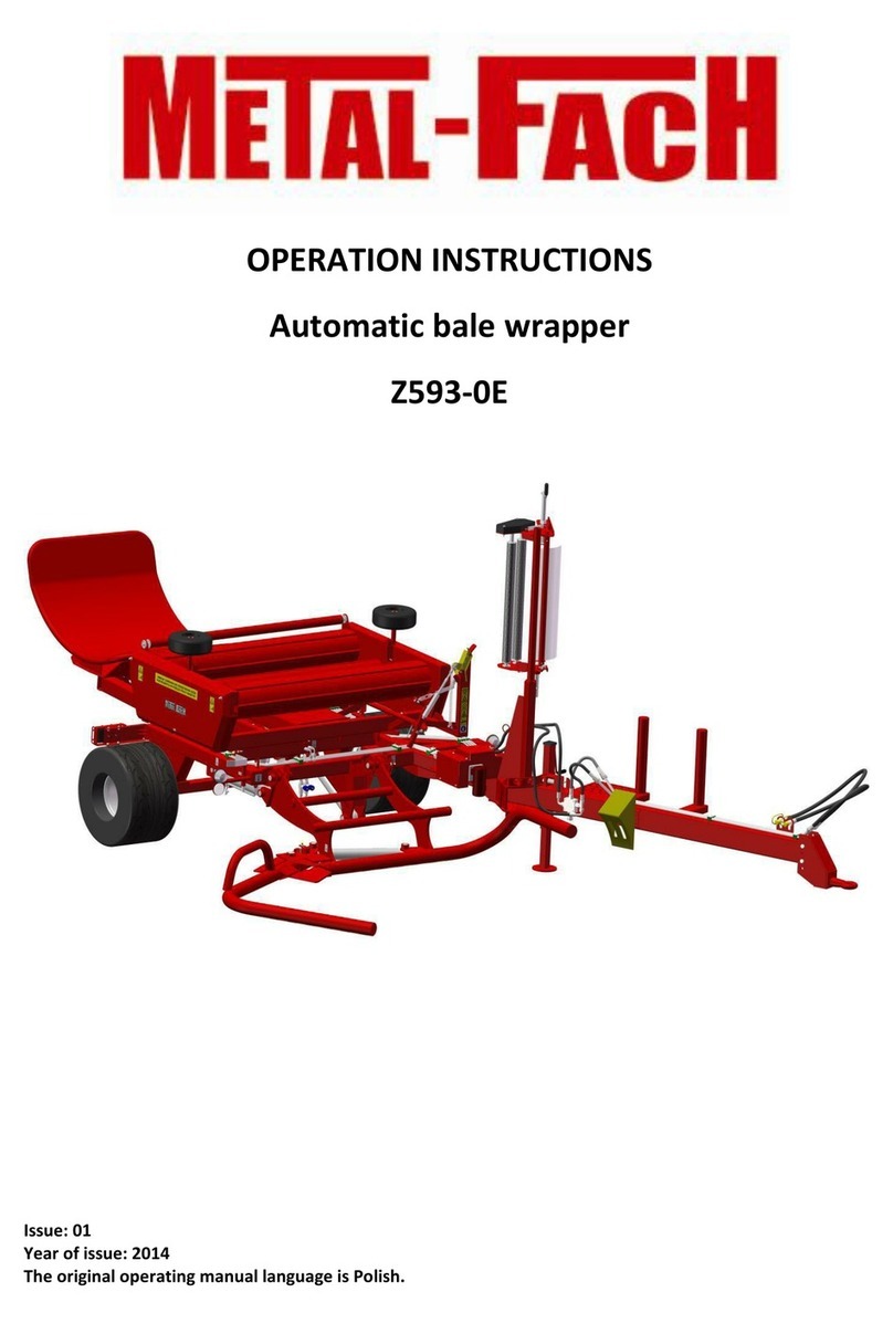
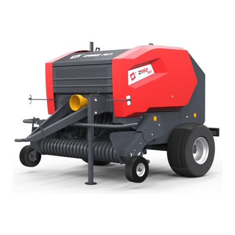
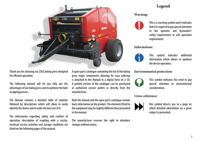
Metal-Fach Z562 User manual

BALER
Z562
INSTRUCTIONS MANUAL –PART I
TRANSLATION OF THE ORIGINAL INSTRUCTIONS MANUAL,
REV. IV
JULY 2018
Instructions manual No. Z562-04-167/2013


INSTRUCTION MANUAL –BALER Z562 3
WARNING
The symbols used in these instructions.
Hazard-warning symbol. This indicates the presence of a serious-hazard
condition, which, if not avoided, can result in death or serious injury. The
symbol warns against the most-dangerous situations.
The symbol pointing to especially important information and
recommendations. Non-compliance with the described
recommendations poses a serious threat of damage to the machine due
to its incorrect operation.
The symbol indicating the possibility of the presence of a hazard which,
if not avoided, can result in death or serious injury. This symbol indicates
a lower level of risk of injury than the symbol including the word
“DANGER”.
The symbol indicating useful information.
The symbol indicating service operations which should be performed
periodically.
DANGER
WARNING

4INSTRUCTION MANUAL –BALER Z562
TABLE OF CONTENTS
PART I
1 General Information..................................................................................................11
1.1 Introduction ...................................................................................................11
1.2 Baler Identification ......................................................................................... 11
1.3 Baler Intended Use........................................................................................13
1.4 Baler Design .................................................................................................. 14
1.5 The Technical Specifications Of The Baler.................................................... 15
1.6 General Safety Principles ..............................................................................16
1.6.1 Safety Signs...................................................................................................24
1.6.2 Warning Signs................................................................................................ 24
1.7 Baler Transport..............................................................................................31
1.7.1 Load Transport............................................................................................... 31
1.7.2 Road Traffic Participant .................................................................................33
1.8 Baler Cleaning ............................................................................................... 34
1.9 Baler Storage.................................................................................................35
1.10 Risk................................................................................................................35
1.10.1 Residual-Risk Description..............................................................................35
1.11 Residual-Risk Assessment ............................................................................ 36
1.12 Dismantling And Disposal.............................................................................. 36
1.13 Accessories.................................................................................................... 36
2 The First Start-Up......................................................................................................37
2.1 The First Start-Up Of The Baler..................................................................... 37
3 Using The Machine ..................................................................................................40
3.1 Foreword........................................................................................................40
3.2 Attaching The Baler To A Tractor ..................................................................40
3.2.1 Connecting With The Lower Tractor Transport Hitch.......................................40
3.2.2 Coupling The Baler With The Rear PTOFF Shaft.......................................... 42
3.2.3 Hydraulic System Installation......................................................................... 43
3.2.4 Lighting Connection.......................................................................................43
3.2.5 Connecting The Control System....................................................................44

INSTRUCTION MANUAL –BALER Z562 5
3.2.6 The Braking System.......................................................................................44
3.2.7 Drive Disconnection.......................................................................................46
3.3 Operational Check.........................................................................................47
3.4 Preparing The Machine For Operation ..........................................................47
3.4.1 Mounting And Operating The Twine-Binding Unit.......................................... 47
3.4.2 Mounting And Operating The Net-Binding Unit.............................................. 48
3.4.3 The Ensilage Applicator.................................................................................50
NAME AND ABBREVIATION INDICES ....................................................................53
ALPHABETICAL INDEX............................................................................................54

6INSTRUCTION MANUAL –BALER Z562
Part II
3.5 Control-Panel Operation...................................................................................8
3.5.1 Switching on the panel..................................................................................9
3.5.2 Switching Off The Panel..............................................................................10
3.5.3 Selecting The Bale-Binding Option .............................................................10
3.5.4 Delay-Time Change ....................................................................................10
3.5.5 Resetting.....................................................................................................10
3.5.6 Zeroing The Workday Counter....................................................................11
3.6 Hydraulic Installation.......................................................................................11
3.6.1 The Standard Hydraulic System..................................................................12
3.6.2 The Optional Hydraulic System...................................................................14
3.7 The Electrical System.....................................................................................15
3.8 Windrow Collection.........................................................................................16
3.8.1 The Principles Of Operation........................................................................16
3.8.2 Operations Description................................................................................16
3.8.3 Straw Collection ..........................................................................................18
3.9 Removing The Accumulated Material.............................................................18
3.9.1 Removing the Accumulated Material...........................................................19
3.9.2 Removing the Accumulated Material on The Rotor.....................................19
3.10 Ending Operations.......................................................................................19
4Maintenance and Adjustment.................................................................................20
4.5 Pick-Up-Wheels Adjustment...........................................................................22
4.6 Adjusting The Drive-Chain Tensioning (Every 10 Hrs Of Work).....................22
4.6.1. Adjusting The Pick-Up Chain Tension Of The Baler To The Feeding Roller
23
4.7 Pick-Up Cam Adjustment................................................................................24
4.8 Replacing The Locking Bolt In The Pick-Up ...................................................26
4.9 Replacing The Locking Bolt In The Supplying Unit.........................................27
4.10 Adjusting The Degree Of Compaction...........................................................28
4.11 Adjusting The Twine-Binding Device.............................................................30
4.11.1 Sharpening The Twine Blades....................................................................30
4.12 Adjusting The Net-Binding Device...............................................................30
4.13 Adjusting The Cover Stop Valve .................................................................31
4.14 Adjusting The Lock......................................................................................32
4.15 Sharpening The Blades...............................................................................33
4.16 Transmission-Fluid Exchange (Once A Year).............................................35
4.17 Lubrication...................................................................................................36

INSTRUCTION MANUAL –BALER Z562 7
4.17.1 Lubricating The Pick-Up..............................................................................38
4.17.2 The Automatic Lubrication System For Chains..........................................40
4.17.3 Lubricating the Bearings.............................................................................42
4.18 Tyres Inspection (Every 30 Days Of Work)................................................42
5Possible Faults.......................................................................................................43
NAME AND ABBREVIATION INDICES .................................................................46
ALPHABETICAL INDEX.........................................................................................47
NOTES...................................................................................................................50

8INSTRUCTION MANUAL –BALER Z562
3.5 Control-Panel Operation
The control panel is fixed in the tractor cab by means of magnetic components. It allows
access to various features of the baler, described below.
The control panel has features suitable for the version of the machine and the market
on which it was purchased. The control panel of the baler comes with the options of twine or
net-binding. It facilitates configuring the applicator and the hydraulic manifold functioning. The
signalling fields of the counter indicate any overloading of the chamber and opening of the
chamber, as well as applicator action, work of the net-binding unit, and hydraulic manifold
action.
Figure 19. Control panel
WARNING!
Pressing the touch screen keys with your nails or sharp or hard objects
is forbidden. Risk of permanent damage to the keyboard.
WARNING

INSTRUCTION MANUAL –BALER Z562 9
Description of control-panel push buttons
Switch –press and hold to activate the counter. Press once again to switch the
counter off.
Applicator –switch on/off the applicator. Press the key to switch the
applicator on. Press once again to switch the applicator off. The green
indicator lamp means that the applicator is running.
Binding –switch on/off the binding. Press and hold the key to activate
the unit. Release the key to switch the bale-binding unit off. The green
indicator lamp means that the bale-binding unit is running.
Hydraulic manifold –press the key to switch on the hydraulic
manifold. After the pre-set delay time, the manifold is activated
automatically. Press the key again before the pre-set delay time has
passed to deactivate the manifold action. The green indicator lamp
means that the hydraulic manifold is running.
Deleting –press and hold the key to delete the workday counter data.
Description of the signalling fields
The red indicator lamp means that the chamber is overloaded.
The yellow indicator lamp means that the chamber has been opened.
3.5.1 Switching on the panel
Connect the counter mounted in the operator's cab to the baling press by means of the
D-SUB 9-pin coupling. Do not use excessive force to plug in. Secure the correctly connected
plug from accidental disconnection by tightening the retaining bolts located on both sides of
the plug. Correct connection is confirmed by a flashing red dot on the display. After the “On/Off”
switch (“Włącznik”) key has been pressed, the control panel does a display test and checks
the supply voltage. The counter display shows “8.8.8.8.”, all the indicator lamps light up, and
the acoustic signal can be heard. Then, the message “U12.2” is displayed which gives the
voltage of the counter-supply system (it means the voltage of 12.2V).

10 INSTRUCTION MANUAL –BALER Z562
Any other figure shown by the counter means that it is faulty. Too low a voltage is
indicated by the counter displaying “Err1” alternately with the voltage value, e.g. “U8.5”
(it means a voltage of 8.5V). The counter indicates an unacceptably high voltage with an
“Err2” message, displayed alternately with the voltage value “U18.5”(it means a voltage of 18.5V).
3.5.2 Switching Off The Panel
Switch the counter by pressing the “On/Off” switch (Włącznik). The display shows a
flashing red dot “8.8.8.8.” After this message, you can disconnect the counter supply.
To disconnect the plug, loosen the locking bolts (on both sides of the plug) and pull the
plug (not the cord) to disconnect.
3.5.3 Selecting The Bale-Binding Option
The option of baler operation (twine or net-binding) is selected after you have
disconnected the counter, when the display shows a flashing red dot “8.8.8.8.” (Section 3.5 2).
Next, simultaneously press and hold the “Binding” and “On/Off” keys. The following operational
options are displayed.
•“OP-1” – twine-binding (the “Binding” key is disabled). The counter generates an
intermittent acoustic signal, and the “Binding” button green indicator lamp is on.
•“OP-2” - net-binding. Press and hold “Binding” to start the work of the net-binding unit.
Release the key to stop the work of the unit. The control panel displays “0”, or the latest
message.
Press “Applicator” or “Manifold” to select the option. Hit “Binding” to confirm the
selection.The control panel enters the selected work mode in the disabled condition (the red
dot is flashing “8.8.8.8.”).
3.5.4 Delay-Time Change
Set the delay time after the counter is switched off, when the red flashing dot “8.8.8.8.”
is lit continuously. Simultaneously, press and hold the “Hydraulic manifold” and “On/Off” keys.
The display shows a message about the delay time for the hydraulic manifold, e.g. “t1.30”,
which means the delay time T1 is 30 seconds. The range of the delay time of the hydraulic
manifold is between 5 and 99 seconds. Press “Applicator” (-) or “Manifold” (+) to change the
delay time. Press “Binding” to confirm. The control panel enters the selected work mode in the
disabled condition (the red dot is flashing “8.8.8.8.”).
3.5.5 Resetting
Reset the option of the baler operation after the counter is off, when the display shows

INSTRUCTION MANUAL –BALER Z562 11
a flashing red dot “8.8.8.8.” Simultaneously, press and hold “Deleting” (red flashing dots
“8.8.8.8.” are displayed) and “On/Off” keys. The following message is displayed “dEFA”. After
releasing the keys, the control panel is reset, it enters the work mode in the disabled condition,
and the display shows a flashing red dot “8.8.8.8.”
3.5.6 Zeroing The Workday Counter
Press and hold “Deleting” to zero the workday counter.
The key must be kept held down until the “0” digit is displayed.
3.6 Hydraulic Installation
WARNING!
Ensure the fluid purity in the tractor-power hydraulic system. The purity
of the fluid must be compliant with condition 20/18/15 of ISO 4406-1996.
WARNING
WARNING!
Ensure the full working order of the hydraulic system. The fluid which
works under high pressure heats up to a temperature which poses a
threat to health.
WARNING
WARNING!
For replacements it is recommended to use original spare parts that will
assure maintaining the baler in full efficiency for a long time of its
operation.
WARNING
WARNING!
Worn or defective hoses in the power hydraulics must be replaced with
new ones.
WARNING

12 INSTRUCTION MANUAL –BALER Z562
3.6.1 The Standard Hydraulic System
Figure 20. Diagram of the standard hydraulic system
The baling-press hydraulic system is supplied from the hydraulic system of the tractor.
Connect the opening/closing of the rear cover and the raising/lowering of the pick-up to the
tractor power hydraulic system by means of a connection line supplying the three-way valve
and, further, the chamber opening actuators and the lowering and lifting pick-up actuators, as
shown in Figure 21.
Pick-up lifting-cylinder
assembly
Three-way electrically
operated valve
Blade-lifting cylinder assembly
Chamber-opening
cylinder assembly

INSTRUCTION MANUAL –BALER Z562 13
Connect the lifting/lowering of the cutter unit blades (optional accessory) to the power
hydraulic system by means of the connection lines, as shown in Figure 21. A dual-section
external hydraulic system of the tractor is required for this system to work.
Figure 21. Control lever
Figure 22. Cutter unit
Pick-up and hatch
control
Lifting
Lowering
Blade control

14 INSTRUCTION MANUAL –BALER Z562
3.6.2 The Optional Hydraulic System
The baling press hydraulic system is supplied from the single-circuit power hydraulic
system of the tractor.
Connect the opening/closing of the rear cover and the raising/lowering of the pick-up to
the tractor power hydraulic system by means of the connection line. Controlling the actuators
of raising and lowering the pick-up is effected by the hydraulic control system located in the
tractor cab. Install the control lever for the baler hydraulics in the cab next to the operator's
seat.
Set the control lever for the baler hydraulics in the position of the baler pick-up/rear
cove control to carry out the check of the hydraulic system. After setting the baler hydraulics-
control lever in the chosen position of the tractor hydraulics control lever, check the operation
functions (lifting and lowering) of the pick-up and cover of the rear rolling press.
Figure 23. Controlling the baler hydraulics
Lifting
Lowering
Pick-up
Chamber

INSTRUCTION MANUAL –BALER Z562 15
3.7 The Electrical System
The baling-press electrical system is supplied from the electrical system of the tractor.
Connect the baler to the tractor electrical system circuit by means of the 7-pin connection cord,
as shown in Figure 24.
Figure 24. Wiring diagram (1 - Connection plug, 2 - Front lamp, 3 - Rear lamp, 4 –Registration-plate lamp)
WARNING!
Check the functioning of the electrical system and lighting each time
before you drive the baler on public roads.
WARNING

16 INSTRUCTION MANUAL –BALER Z562
3.8 Windrow Collection
3.8.1 The Principles Of Operation
The baler collects the material from the fields by means of a hydraulically raised pick-
up. The picked-up material is pressed and rolled into cylindrical rolls, and then it is bound with
twine or net, and finally tossed out of the rolling chamber, as shown in the Figure below.
Figure 25. Forming bales
3.8.2 Operations Description
The picked-up material is fed into the rolling chamber, where the rolling rollers move to
compact and roll it into a pressed roll. The ending of the rolling action is signalled by the
compaction-degree indicator A (Section 4.6.) reaching the lower position of the yellow field and
generating the acoustic signal.
When the acoustic signal is off, the bale is bound with a twine (twine-binding is
automatic. Net binding requires control-panel use). At that moment you must stop the tractor
(do not switch the engine off) without pausing the PTOff operation. The end of the twine is
gripped between the revolving bale and the revolving press roller. The bale twine-binding
indicator B moves towards the belt wheel (sequence 1 in Figure 26), and then it moves to the
end position on the opposite side (sequence 2) and it returns to the original position (sequence
3).
Figure 26. The bale twine-binding indicator

INSTRUCTION MANUAL –BALER Z562 17
Throughout that time, the engine maintains the press devices in motion through the
rear PTOff. After the indicator B has returned to the home position, open the rolling chamber.
The control panel indicates the press cover opening by lighting the pictogram of the press
cover’s lifting. The rolled bale rolls out to the ground along the collector and facilitates the
cover’s closing and resuming the crop collection and swathe rolling.
After approximately four seconds from the closing of the chamber cover, release the
control lever of the tractor’s hydraulic manifold to allow the correct clamping of the mechanical
locks protecting the chamber from unauthorised opening.
Prior to harvesting, the material must be properly prepared by raking. Subsequently,
form the windrows into strips not wider than 1.1 m in width. Collect the shaped windrow strips
as shown in the following diagram. Adjust the length of the straight sections to the particular
conditions. To prevent clogging the baler, the width and height of the windrows should be equal
throughout their lengths. Slow down at wider windrow sections.
Figure 27. Windrow collection
Mow grass and other papilionaceae intended for ensilaging and wrapping in the first
phase of earing (preferably in the afternoon). Next day, after a few hours of drying, gather the
mowed material with the use of balers. Keep the highest-possible bale-compaction degree.
The recommended driving speed for the tractor is up to 10 km/h.

18 INSTRUCTION MANUAL –BALER Z562
3.8.3 Straw Collection
Figure 28. Straw collection - machine preparation
Prepare the machine for straw collection by doing the following.
•Run the cord through holes 4 or 5 of the lever (Figure 38)
•The manufacture’s recommended maximum cord tension should be 20 mm, as
shown in Figure 28
•Install the drawbar by means of adjusting hole No. 2 (Section 3.2.1.); as standard,
hole No. 3 is used
•Dismantle the clamp, unit 14 (Figure 4).
3.9 Removing The Accumulated Material
During material pick-up, it is possible that it will accumulate on the pick-up and rotor or
collector. Clogging is the result of improperly adjusting the speed to the harvest conditions,
and improperly formed windrow.
DANGER!
Removing accumulated material during the machine operation is
forbidden.
DANGER
DANGER!
Use special care during the removal of the accumulated material, as the
rotor zone is dangerous due to sharp blades.
DANGER

INSTRUCTION MANUAL –BALER Z562 19
3.9.1 Removing the Accumulated Material
To remove the material accumulated on the pick-up, carry out the following.
•Switch off the control panel
•Stop the tractor, remove the ignition keys, and wait until all the moving components of
the machine come to a complete stop
•Remove the clamp for the cut material, located over the pick-up and collector, to
remove the material in the front section
•Manually remove the accumulated material
•Reinstall the clamp for the cut material.
3.9.2 Removing the Accumulated Material on The Rotor
To remove the material accumulated on the rotor, carry out the following.
•Stop the tractor, remove the ignition keys and wait until all the moving components of
the machine come to a complete stop
•Check the bolt protections on the rotor, as per Section 4.5
•Remove the clamp for the cut material, located over the pick-up, to remove the
material in the front section
•Manually remove the accumulated material
•Reinstall the clamp for the cut material.
3.10 Ending Operations
Always after you finish work, carry out the following.
•Disable the counter and protect it from moisture
•Store the baler on flat, level, and paved surface
•Disconnect the hydraulic system and electric-circuit supplies
•Prop up the baler with the use of the support foot
•Disconnect the machine drawbar from the transport hitch of the tractor
•Disable the PTO shaft and leave it on the support. Install the caps on the PTOff and PTOn terminals
•Disconnecting the baler from the tractor with the bale in the rolling chamber is forbidden.
•Ensure the machine is cleaned and thoroughly inspected, paying attention to the
quality of the protective paint coating, and repairing it as required.
•Protect the rubber components, such as hydraulic hoses and baler tyres, from
exposure to sunlight.
During longer stoppage periods, the manufacturer recommends storing the baler in a
dry room or under roofing, which protects the baler from the effects of weather conditions.

20 INSTRUCTION MANUAL –BALER Z562
4 Maintenance and Adjustment
Before you commence any maintenance work, follow the safety rules set out in
Section 1.6 “General safety principles”.
If the baler is connected to the tractor, apply the manual brake, disable the engine, and
remove the ignition key. Remember to switch off the control panel too.
During maintenance work, when the chamber is open, use the locks to secure the
actuators.
Figure 29. Locks for securing the actuators
Secure the raised baler cover in its upper position, as shown in Figure 29. On both
sides of the baler, use clamps (2) fixed to the upper pins of the hydraulic cylinders (1) to secure
them. Move the clamps (2) fully upwards so that they engage with the stretched cylinder rods.
Lock them with locking pins (4) against unauthorised cover closing. Unlock the clamps of the
cover after completing the planned activities.
DANGER!
All activities related to maintenance and adjustment must be carried out
during machine stoppage and when all the moving parts of the machine
have stopped.
DANGER
WARNING!
Use original spare parts only.
WARNING
Other manuals for Z562
2
Table of contents
Other Metal-Fach Farm Equipment manuals
Popular Farm Equipment manuals by other brands
LEMKEN
LEMKEN Zirkon 10 KA operating instructions
sitrex
sitrex DM/6 ASSEMBLY, USE AND MAINTENANCE SPARE PARTS LIST

MK Martin
MK Martin land plane Operator's manual
Kverneland
Kverneland a-drill operating manual

AKO-Agrartechnik
AKO-Agrartechnik BA-1199 instruction manual
Dingsheng Tiangong
Dingsheng Tiangong PY180H operating manual
