manuals.online logo
Brands
  1. Home
  2. •
  3. Brands
  4. •
  5. WIL-RICH
  6. •
  7. Farm Equipment
  8. •
  9. WIL-RICH 11 XL2 Series User manual

WIL-RICH 11 XL2 Series User manual

ASSEMBLY MANUAL
3-BAR COIL TINE HARROW
WITH BASKET
(INCLUDES HYDRAULIC OPTION)
Printed in USA 74389 10/20
Coil Tine Harrow with Basket
74389
Table of Contents
3
COIL TINE HARROW WITH HYDRAULIC BASKET
1. Introduction
Introduction ..........................................................................................................5
2. Harrow Basket Assembly
Harrow Basket Assembly .....................................................................................8
3. Harrow Layouts
11 XL2 Harrow Bracket Bolt Hole Locations........................................................10
11 XL2 19-20’ Coil Tine Harrow with Basket Layout............................................11
11 XL2 25’ Coil Tine Harrow with Basket Layout.................................................12
11 XL2 25-27’ Coil Tine Harrow with Basket Layout............................................13
11 XL2 30-32’ Coil Tine Harrow with Basket Layout............................................14
11 XL2 30-39’ Coil Tine Harrow with Basket Layout............................................15
13 XL2/QX2 32’ Coil Tine Harrow with Basket Layout.........................................16
13 XL2/QX2 32-42’ Coil Tine Harrow with Basket Layout ...................................17
13 XL2/QX2 32-45’ Coil Tine Harrow with Basket Layout ...................................18
13 XL2/QX2 37’ Coil Tine Harrow with Basket Layout.........................................19
13 XL2/QX2 37-50’ Coil Tine Harrow with Basket Layout ...................................20
13 XL2/QX2 46-50’ Coil Tine Harrow with Basket Layout ...................................21
13 XL2/QX2 55’ Coil Tine Harrow with Basket Layout.........................................22
13 XL2/QX2 55-60’ Coil Tine Harrow with Basket Layout ...................................23
4. Hydraulic Lift Kit Assembly
Hydraulic Lift Kit Assembly..................................................................................24
5. Hydraulic Layout
13 XL2/QX2 32’ Basket Hydraulics.....................................................................26
13 XL2/QX2 32-42’ Basket Hydraulics................................................................28
13 XL2/QX2 32-45’ Basket Hydraulics................................................................30
13 XL2/QX2 37’ Basket Hydraulic.......................................................................32
13 XL2/QX2 37-50’ Basket Hydraulics................................................................34
13 XL2/QX2 45-50’ Basket Hydraulics................................................................36
13 XL2/QX2 55’ Basket Hydraulics.....................................................................38
13 XL2/QX2 55-60’ Basket Hydraulics................................................................40
Table of Contents
Coil Tine Harrow with Basket
74389 4
Coil Tine Harrow with Basket
74389
1. Introduction
5
Introduction - 3-Bar Coil Tine Harrow with Basket Assembly Instructions
These instructions apply to the following models.
Model Serial number
3-Bar Coil Tine Harrow with Basket All
Your model number may not be listed if these instructions were published before your machine was
manufactured.
Shipping damage and missing parts
Inspect the machine and parts carefully for possible damage that occurred during shipping. Contact the
shipping company immediately if damage is found..
Illustrations
The illustrations used will not always be identical to your specific model or configuration. However, the
procedure shown is the same unless otherwise noted.
Direction references
Right and left, as used in these installation instructions, are determined by facing the direction the machine
will travel when in use.
Bolt torques
Always replace hardware with the same grade or class. Tighten all hardware according to torque values
listed in the machine service manual unless otherwise specified in these instructions.
1. Introduction
Coil Tine Harrow with Basket
74389
6
Important safety information
This is the safety alert symbol. It means ATTENTION! BECOME ALERT! YOUR SAFETY IS
INVOLVED! It will direct your attention to information that concerns your safety.
Read and understand all safety information in the machine operator's manual before
continuing with these instructions.
Most personal injuries are the result of failure to observe basic safety rules and precautions. In most cases,
an injury can be avoided by recognizing hazardous situations before an injury occurs and taking appropriate
action to remove or avoid the hazard.
The person installing this kit must have the necessary training, skills, and tools.
WARNING:
To avoid personal injury and/or machine damage, do the following before starting to
install this kit:
• Use personal safety equipment appropriate to the task such as:
Protective eye wear
Gloves
Steel-toed shoes
Hearing protection
• Park the machine on a solid level surface.
• Disengage the power take-off (PTO), if equipped.
• Put the transmission in the parking position and apply the park brake.
• Turn off the control console.
• Stop the engine and take the key with you.
• Look and Listen! Make sure all moving parts have stopped.
• Put blocks in front of and behind the machine wheels before working on or under the machine.
• Remove or relieve all sources of stored energy such as:
Disconnect the battery
Relieve hydraulic or fuel pressure
Relieve air pressure
Relieve or block mechanical spring pressure
Properly block or lock pivoting joints
• Clean oil, dirt, and crop material from the area on the machine where the work is to be done.
Coil Tine Harrow with Basket
74389
1. Introduction
7
Prepare for assembly
WARNING:
Components can be heavy. Severe injury can result from improper lifting technique. Use
appropriate lifting equipment for heavy components.
Read this section carefully before assembly. Refer to the Parts Catalog for additional component
illustrations while assembling the machine.
Part numbers are shown on labels on the parts.
Hardware numbers are shown on labels on the hardware or on the container the hardware is in.
Carefully remove all the parts and hardware included. Make sure nothing was damaged or missing.
Tighten all hardware according to standard torque values unless specified in these instructions. See the
torque charts in this publication for more information.
Always replace hardware with the same grade or class.
Use all the nuts and bolts in the correct locations. This will prevent damage to the machine.
IMPORTANT: When two or more bolts are being used on a part, always insert the bolts and loosely
tighten the nuts. Once the correct location has been reached, tighten the nuts evenly to prevent
misalignment or distortion of the parts. Tighten all U-bolt nuts evenly and to the same torque to prevent
misalignment or distortion.
Select a large, flat, and hard surface for assembly of machine.
IMPORTANT: Keep all parts in the assigned containers until the parts are to be used.
NOTE: Some items will be assembled at the factory.
Right-hand and left-hand, as used in this manual, are determined by facing the direction the machine will
travel when in use.
Service parts
The illustrations and part numbers in this publication are supplied for component identification only when
assembling the machine. When ordering replacement parts, always use the part numbers from the parts
catalog.
For a complete list of available service parts, go to www.wil-rich.com or contact your dealer.
GUID-0CC3542C-6DFD-442D-B388-BA47ED91B876 [V2]
2. Harrow Basket Assembly
Coil Tine Harrow with Basket
74389
8
Installing the Harrow Basket Assembly:
Determine the correct position of the harrow arm on the
rear tube of the frame. See pages 10 through 17 for
layout information.
Install the mount (1) of the harrow arm over the rear
tube of the frame (2).
Attach the mount arm assemblies to the frame of the
implement using the harrow lock plate (1) and supplied
5/8” x 5-1/2” bolts (2), lock washers, and nuts to install
the harrow mount to the frame.
NOTE: The bolt holes in the harrow lock plate are offset.
Orientate the harrow lock plate so the bolt holes are
offset towards the top of the harrow arm.
NOTE: Exact arm location could vary either direction,
dependent on implement accessories and options. Do
not tighten arms completely until all sections are in
place.
Install the harrow section bars.
Select a harrow bar section of the correct width for the
harrow section you are working on. Refer to pages 10
through 17 for correct harrow section widths.
NOTE: The harrow arms must be in the correct position
and loosely installed before the harrow section bars can
be installed.
1
2
12
1.
2.
3.
Coil Tine Harrow with Basket
74389
2. Harrow Basket Assembly
9
Use the supplied 1/2-13 x 1-1/2” bolts (1), lock washers
(2), and nuts (3) too install the first harrow section bar to
the first pair of pivot brackets.
See pages 10 (for 11’ Mainframe XL2) and 16 through 23
to determine what hole on the harrow section bar you
need to be using when installing the harrow section bar to
the pivot bracket.
Repeat this step for the second and third harrow section
bar for each section.
Find the reel basket assembly (1) for the correct width of
each section.
Loosely install the reel basket assembly to the reel
mounts (2) use four of the supplied 5/8-11 x 3” x 4”
U-bolts, lock washers, and nuts to install the reel basket
assembly to the basket mounts.
After installing the reel basket assemblies, adjust the
position of the reel basket assembly in the U-bolts so that
there is 3/4” between the ends of each of the basket
mounts.
Tighten all hardware on the harrow sections, reel basket
assembly, and the hardware attaching the harrow arms to
the frame using the correct torque.
Make sure there is no interference between components
when folding the machine. Adjust the position of any
components in the event of interference or prevention of
wings from folding.
22
1
3
1
2
3/4”
4.
5.
6.
7.
8.
3. Harrow Layouts
Coil Tine Harrow with Basket
74389
10
For 11' main frame XL2 models, assemble the section bars to the mount arm assemblies as shown
above. The harrow mounting arm locations on the mounting arm location chart are based on the
assembly of the harrow bars as shown above.
NOTE: Because of changing mounting conditions it may be necessary to move the complete basket
arm laterally. In this situation you will need to shift the harrow bars accordingly, move each bar the
same number of holes to ensure the correct spacing of the tines.
11 XL2 Harrow Bracket Bolt Hole Locations
Coil Tine Harrow with Basket
74389
3. Harrow Layouts
11
Arm Location:
Arm location is shown above.
These measurements are from the
center of the machine to the cen-
ter of the harrow arm.
Exact arm location could vary
either direction, dependent on im-
plement accessories and options.
Do not tighten arms completely
until all sections are in place
Harrow Section Bar Mounting:
Harrow section bar mounting hole locations
are shown on page 10. Assemble the section
bars to the mount arm assemblies as page
10 shows.
The harrow mounting arm locations on the
mounting arm location are based on the as-
sembly of the harrow bars as shown above.
Harrow and Basket Spacing:
The spacing between the harrow bar
sections should be approximately 9
inches. This may vary slightly due to
interferences.
Starting basket location for the left side
mainframe 7-1/2’ basket is 16-3/4” from
the edge of the basket to the edge of
the arm. Space each following basket
section 3/4” apart.
11 XL2 19-20' COIL TINE HARROW WITH BASKET
Center of Machine
113" 89" 60" 35" 4" 55" 89" 113"
4-1/2' Section 4-1/2' Section 7-1/2' Section 4-1/2' Section
3. Harrow Layouts
Coil Tine Harrow with Basket
74389
12
Arm Location:
Arm location is shown above.
These measurements are from the
center of the machine to the cen-
ter of the harrow arm.
Exact arm location could vary
either direction, dependent on im-
plement accessories and options.
Do not tighten arms completely
until all sections are in place
Harrow Section Bar Mounting:
Harrow section bar mounting hole locations
are shown on page 10. Assemble the
section bars to the mount arm assemblies
as page 10 shows.
The harrow mounting arm locations on the
mounting arm location are based on the as-
sembly of the harrow bars as shown above.
Harrow and Basket Spacing:
The spacing between the harrow bar
sections should be approximately 9
inches. This may vary slightly due to
interferences.
Starting basket location for the left side
mainframe 7-1/2’ basket is 16-3/4” from
the edge of the basket to the edge of
the arm. Space each following basket
section 3/4” apart.
11 XL2 25' COIL TINE HARROW WITH BASKET
Center of Machine
144" 90" 52" 21" 22" 52" 94" 146"
7-1/2' Section 6' Section 6' Section 7-1/2' Section
Arm Location:
Arm location is shown above.
These measurements are from the
center of the machine to the cen-
ter of the harrow arm.
Exact arm location could vary
either direction, dependent on im-
plement accessories and options.
Do not tighten arms completely
until all sections are in place
Harrow Section Bar Mounting:
Harrow section bar mounting hole locations
are shown on page 10. Assemble the section
bars to the mount arm assemblies as page
10 shows.
The harrow mounting arm locations on the
mounting arm location are based on the as-
sembly of the harrow bars as shown above
Harrow and Basket Spacing:
The spacing between the harrow bar
sections should be approximately 9
inches. This may vary slightly due to
interferences.
Starting basket location for the left side
mainframe 7-1/2’ basket is 16-3/4” from
the edge of the basket to the edge of
the arm. Space each following basket
section 3/4” apart.
11 XL2 25-27' COIL TINE HARROW WITH BASKET
Center of Machine
148" 98" 62" 10" 32" 62" 98" 148"
7-1/2' Section 7-1/2' Section 6' Section 7-1/2' Section
Coil Tine Harrow with Basket
74389
3. Harrow Layouts
13
Arm Location:
Arm location is shown above.
These measurements are from the
center of the machine to the cen-
ter of the harrow arm.
Exact arm location could vary
either direction, dependent on im-
plement accessories and options.
Do not tighten arms completely
until all sections are in place
Harrow Section Bar Mounting:
Harrow section bar mounting hole locations
are shown on page 10. Assemble the section
bars to the mount arm assemblies as page
10 shows.
The harrow mounting arm locations on the
mounting arm location are based on the as-
sembly of the harrow bars as shown above
Harrow and Basket Spacing:
The spacing between the harrow bar
sections should be approximately 9
inches. This may vary slightly due to
interferences.
Starting basket location for the left side
mainframe 7-1/2’ basket is 16-3/4” from
the edge of the basket to the edge of
the arm. Space each following basket
section 3/4” apart.
11 XL2 25-27' COIL TINE HARROW WITH BASKET
Center of Machine
148" 98" 62" 10" 32" 62" 98" 148"
7-1/2' Section 7-1/2' Section 6' Section 7-1/2' Section
3. Harrow Layouts
Coil Tine Harrow with Basket
74389
14
11 XL2 30-32’ COIL TINE HARROW WITH BASKET
Arm Location:
Arm location is shown above.
These measurements are from the
center of the machine to the cen-
ter of the harrow arm.
Exact arm location could vary
either direction, dependent on im-
plement accessories and options.
Do not tighten arms completely
until all sections are in place
Harrow Section Bar Mounting:
Harrow section bar mounting hole locations
are shown on page 10. Assemble the
section bars to the mount arm assemblies
as page 10 shows.
The harrow mounting arm locations on the
mounting arm location are based on the as-
sembly of the harrow bars as shown above
Harrow and Basket Spacing:
The spacing between the harrow bar
sections should be approximately 9
inches. This may vary slightly due to
interferences.
Starting basket location for the left side
mainframe 7-1/2’ basket is 16” from
the edge of the basket to the edge of
the arm. Space each following basket
section 3/4” apart.
Center of Machine
184" 152" 122" 98" 62" 12" 24" 64" 94" 118" 152" 184"
4-1/2' Section4-1/2' Section 6' Section 7-1/2' Section 6' Section 6' Section
Coil Tine Harrow with Basket
74389
3. Harrow Layouts
15
11' XL2 30-39’ COIL TINE HARROW WITH BASKET
Arm Location:
Arm location is shown above.
These measurements are from the
center of the machine to the cen-
ter of the harrow arm.
Exact arm location could vary
either direction, dependent on im-
plement accessories and options.
Do not tighten arms completely
until all sections are in place
Harrow Section Bar Mounting:
Harrow section bar mounting hole locations
are shown on page 10. Assemble the
section bars to the mount arm assemblies
as page 10 shows.
The harrow mounting arm locations on the
mounting arm location are based on the as-
sembly of the harrow bars as shown above.
Harrow and Basket Spacing:
The spacing between the harrow bar
sections should be approximately 9
inches. This may vary slightly due to
interferences.
Starting basket location for the left side
mainframe 7-1/2’ basket is 16” from
the edge of the basket to the edge of
the arm. Space each following basket
section 3/4” apart.
Center of Machine
228" 188" 150" 98" 62" 12" 24" 64" 102" 154" 188" 228"
6' Section6' Section 7-1/2' Section 7-1/2' Section 6' Section 7-1/2' Section
3. Harrow Layouts
Coil Tine Harrow with Basket
74389
16
13 XL2/QX2 32’ COIL TINE HARROW WITH BASKET
2
4
1
12
14
11
5
7
4
2
4
1
4
6
3
7
9
6
198-3/4" 174" 149-1/4" 124-1/2" 77-1/4" 18-3/4" 15" 60" 98-3/4" 127-1/2" 156-3/4" 174-3/4"
4-1/2' Section
4-1/2' Section
6' Section
7-1/2' Section
6' Section
6' Section
Arm Location:
Arm location is shown above.
These measurements are from the
center of the machine to the cen-
ter of the harrow arm.
Exact arm location could vary
either direction, dependent on im-
plement accessories and options.
Do not tighten arms completely
until all sections are in place
Harrow Section Bar Mounting:
Harrow section bar mounting hole locations
are shown above. Assemble the section bars
to the mount arm assemblies as the numbers
above show.
The harrow mounting arm locations on the
mounting arm location are based on the as-
sembly of the harrow bars as shown above.
Harrow and Basket Spacing:
The spacing between the harrow bar
sections should be approximately 9
inches. This may vary slightly due to
interferences.
Starting basket location for the left side
mainframe 7-1/2’ basket is 15-1/4” from
the edge of the basket to the edge of
the arm. Space each following basket
section 3/4” apart.
Center of Machine
Bolt hole location.
Refer to step 4.
of harrow arm
assembly.
Coil Tine Harrow with Basket
74389
3. Harrow Layouts
17
13 XL2/QX2 32-42’ COIL TINE HARROW WITH BASKET
Arm Location:
Arm location is shown above.
These measurements are from the
center of the machine to the cen-
ter of the harrow arm.
Exact arm location could vary
either direction, dependent on im-
plement accessories and options.
Do not tighten arms completely
until all sections are in place
Harrow Section Bar Mounting:
Harrow section bar mounting hole locations
are shown above. Assemble the section bars
to the mount arm assemblies as the numbers
above show.
The harrow mounting arm locations on the
mounting arm location are based on the as-
sembly of the harrow bars as shown above.
Harrow and Basket Spacing:
The spacing between the harrow bar
sections should be approximately 9
inches. This may vary slightly due to
interferences.
Starting basket location for the left side
mainframe 7-1/2’ basket is 16” from
the edge of the basket to the edge of
the arm. Space each following basket
section 3/4” apart.
243-1/4" 214" 186-1/2" 159-1/2" 130-1/4" 110" 74" 20" 20-1/2" 70" 110-1/2" 130-3/4" 160 184-3/4" 216-1/4" 243-1/4"
4-1/2' Section
6' Section
4-1/2' Section
6' Section
4-1/2' Section
4-1/2' Section
7-1/2' Section
7-1/2' Section
3
5
2
3
5
2
5
7
4
5
7
4
5
7
4
2
4
1
2
4
1
8
10
7
Center of Machine
Bolt hole location.
Refer to step 4.
of harrow arm
assembly.
3. Harrow Layouts
Coil Tine Harrow with Basket
74389
18
Arm Location:
Arm location is shown above.
These measurements are from the
center of the machine to the cen-
ter of the harrow arm.
Exact arm location could vary
either direction, dependent on im-
plement accessories and options.
Do not tighten arms completely
until all sections are in place
Harrow Section Bar Mounting:
Harrow section bar mounting hole locations
are shown above. Assemble the section bars
to the mount arm assemblies as the numbers
above show.
The harrow mounting arm locations on the
mounting arm location are based on the as-
sembly of the harrow bars as shown above.
Harrow and Basket Spacing:
The spacing between the harrow bar
sections should be approximately 9
inches. This may vary slightly due to
interferences.
Starting basket location for the left side
mainframe 7-1/2’ basket is 16-3/4” from
the edge of the basket to the edge of
the arm. Space each following basket
section 3/4” apart.
13 XL2/QX2 32-45’ COIL TINE HARROW WITH BASKET
260-1/2" 211" 175" 150-1/4" 121" 96-1/4" 58" 10-3/4" 23" 59" 97-1/4" 119-3/4" 148-3/4" 178-1/4" 221" 226"
4-1/2' Section
7-1/2' Section
4-1/2' Section
7-1/2' Section
4-1/2' Section
4-1/2' Section
7-1/2' Section
6' Section
7
9
6
4
6
3
4
6
3
6
8
5
7
9
6
4
6
3
2
4
1
3
5
2
Center of Machine
Bolt hole location.
Refer to step 4.
of harrow arm
assembly.
Coil Tine Harrow with Basket
74389
3. Harrow Layouts
19
13 XL2/QX2 37’ COIL TINE HARROW WITH BASKET
Arm Location:
Arm location is shown above.
These measurements are from the
center of the machine to the cen-
ter of the harrow arm.
Exact arm location could vary
either direction, dependent on im-
plement accessories and options.
Do not tighten arms completely
until all sections are in place
Harrow Section Bar Mounting:
Harrow section bar mounting hole locations
are shown above. Assemble the section bars
to the mount arm assemblies as the numbers
above show.
The harrow mounting arm locations on the
mounting arm location are based on the as-
sembly of the harrow bars as shown above.
Harrow and Basket Spacing:
The spacing between the harrow bar
sections should be approximately 9
inches. This may vary slightly due to
interferences.
Starting basket location for the left side
mainframe 7-1/2’ basket is 17-3/4” from
the edge of the basket to the edge of
the arm. Space each following basket
section 3/4” apart.
216-3/4" 176-1/4" 149-1/4" 113-1/4" 75" 21" 21-3/4" 69" 114" 147-3/4" 177" 215-1/4"
6' Section
6' Section
6' Section
7-1/2' Section
7-1/2' Section
6' Section
3
5
2
7
9
6
6
8
5
6
8
5
3
5
2
5
7
4
Center of Machine
Bolt hole location.
Refer to step 4.
of harrow arm
assembly.
3. Harrow Layouts
Coil Tine Harrow with Basket
74389
20
13 XL2/QX2 37-50’ COIL TINE HARROW WITH BASKET
Arm Location:
Arm location is shown above.
These measurements are from the
center of the machine to the cen-
ter of the harrow arm.
Exact arm location could vary
either direction, dependent on im-
plement accessories and options.
Do not tighten arms completely
until all sections are in place
Harrow Section Bar Mounting:
Harrow section bar mounting hole locations
are shown above. Assemble the section bars
to the mount arm assemblies as the numbers
above show.
The harrow mounting arm locations on the
mounting arm location are based on the as-
sembly of the harrow bars as shown above.
Harrow and Basket Spacing:
The spacing between the harrow bar
sections should be approximately 9
inches. This may vary slightly due to
interferences.
Starting basket location for the left side
mainframe 7-1/2’ basket is 19-1/4” from
the edge of the basket to the edge of
the arm. Space each following basket
section 3/4” apart.
7
9
6
4
6
3
6
8
5
7
9
6
8
10
7
7
9
6
7
9
6
3
5
2
291" 257-1/4" 207-3/4" 178-1/2" 138" 111" 63-3/4" 23-1/4" 21-3/4" 64-1/2" 109-1/2" 138-3/4" 179-1/4" 210-3/4" 253-1/2" 291-3/4"
6' Section
6' Section
6' Section
6' Section
6' Section
6' Section
7-1/2' Section
7-1/2' Section
Center of Machine
Bolt hole location.
Refer to step 4.
of harrow arm
assembly.

This manual suits for next models

2

Other WIL-RICH Farm Equipment manuals

WIL-RICH 2550 User manual

WIL-RICH

WIL-RICH 2550 User manual

WIL-RICH SoilPro 513 User manual

WIL-RICH

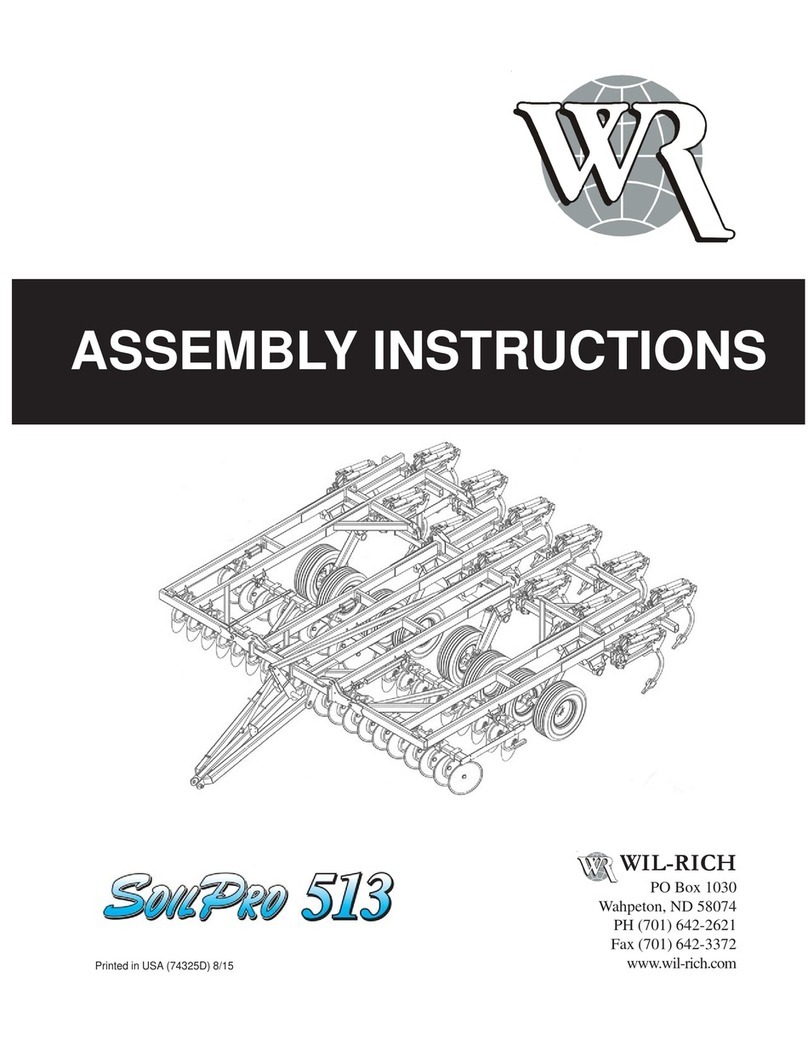
WIL-RICH SoilPro 513 User manual

WIL-RICH 5850 User manual

WIL-RICH

WIL-RICH 5850 User manual

WIL-RICH SOIL FINISHER 34FT User manual

WIL-RICH

WIL-RICH SOIL FINISHER 34FT User manual

WIL-RICH 483 Chisel Pro User manual

WIL-RICH

WIL-RICH 483 Chisel Pro User manual

WIL-RICH PT2200 FWD User manual

WIL-RICH

WIL-RICH PT2200 FWD User manual

WIL-RICH 483 Chisel Pro User manual

WIL-RICH

WIL-RICH 483 Chisel Pro User manual

WIL-RICH 5810 User manual

WIL-RICH

WIL-RICH 5810 User manual

WIL-RICH 657 DISC CHISEL User manual

WIL-RICH

WIL-RICH 657 DISC CHISEL User manual

WIL-RICH XL2 User manual

WIL-RICH

WIL-RICH XL2 User manual

WIL-RICH SoilPro 513 User manual

WIL-RICH

WIL-RICH SoilPro 513 User manual

WIL-RICH 2510 User manual

WIL-RICH

WIL-RICH 2510 User manual

Popular Farm Equipment manuals by other brands

Degelman PRO-TILL 14 Operator's & parts manual

Degelman

Degelman PRO-TILL 14 Operator's & parts manual

Baroness LH52 Owner's operating manual

Baroness

Baroness LH52 Owner's operating manual

Roxell Discaflex user guide

Roxell

Roxell Discaflex user guide

UNIA TWISTER operating instructions

UNIA

UNIA TWISTER operating instructions

sitrex SR 320/8 H Use and Maintenance Spare Parts List

sitrex

sitrex SR 320/8 H Use and Maintenance Spare Parts List

Hardi COMMANDER TWIN FORCE Instruction book

Hardi

Hardi COMMANDER TWIN FORCE Instruction book

J&M 1012 Operator's manual

J&M

J&M 1012 Operator's manual

Samon SU2M manual

Samon

Samon SU2M manual

Westward DUPLEX 3000 Operator's manual

Westward

Westward DUPLEX 3000 Operator's manual

Curtis Kubota L47 TLB Cab Installation & owner's manual

Curtis

Curtis Kubota L47 TLB Cab Installation & owner's manual

Duratech HAYBUSTER 107 DRILL Operating Instructions and Parts Reference

Duratech

Duratech HAYBUSTER 107 DRILL Operating Instructions and Parts Reference

breviglieri MEKFARMER 80 Operating and maintenance manual

breviglieri

breviglieri MEKFARMER 80 Operating and maintenance manual

Gronomics CCPC 45-45 Assembly instruction

Gronomics

Gronomics CCPC 45-45 Assembly instruction

NAMYSLO DEEP Series manual

NAMYSLO

NAMYSLO DEEP Series manual

Digga DOZER BLADE Operator's & parts manual

Digga

Digga DOZER BLADE Operator's & parts manual

Claas AVERO Information and Basic Field Settings

Claas

Claas AVERO Information and Basic Field Settings

AGROdeviate Hawkins Corn Reel installation manual

AGROdeviate

AGROdeviate Hawkins Corn Reel installation manual

Meijer Holland Rambo 3 manual

Meijer Holland

Meijer Holland Rambo 3 manual

manuals.online logo
manuals.online logoBrands
  • About & Mission
  • Contact us
  • Privacy Policy
  • Terms and Conditions

Copyright 2025 Manuals.Online. All Rights Reserved.