Di-Acro 2 ROD PARTER User manual
REV. E 9/12
1
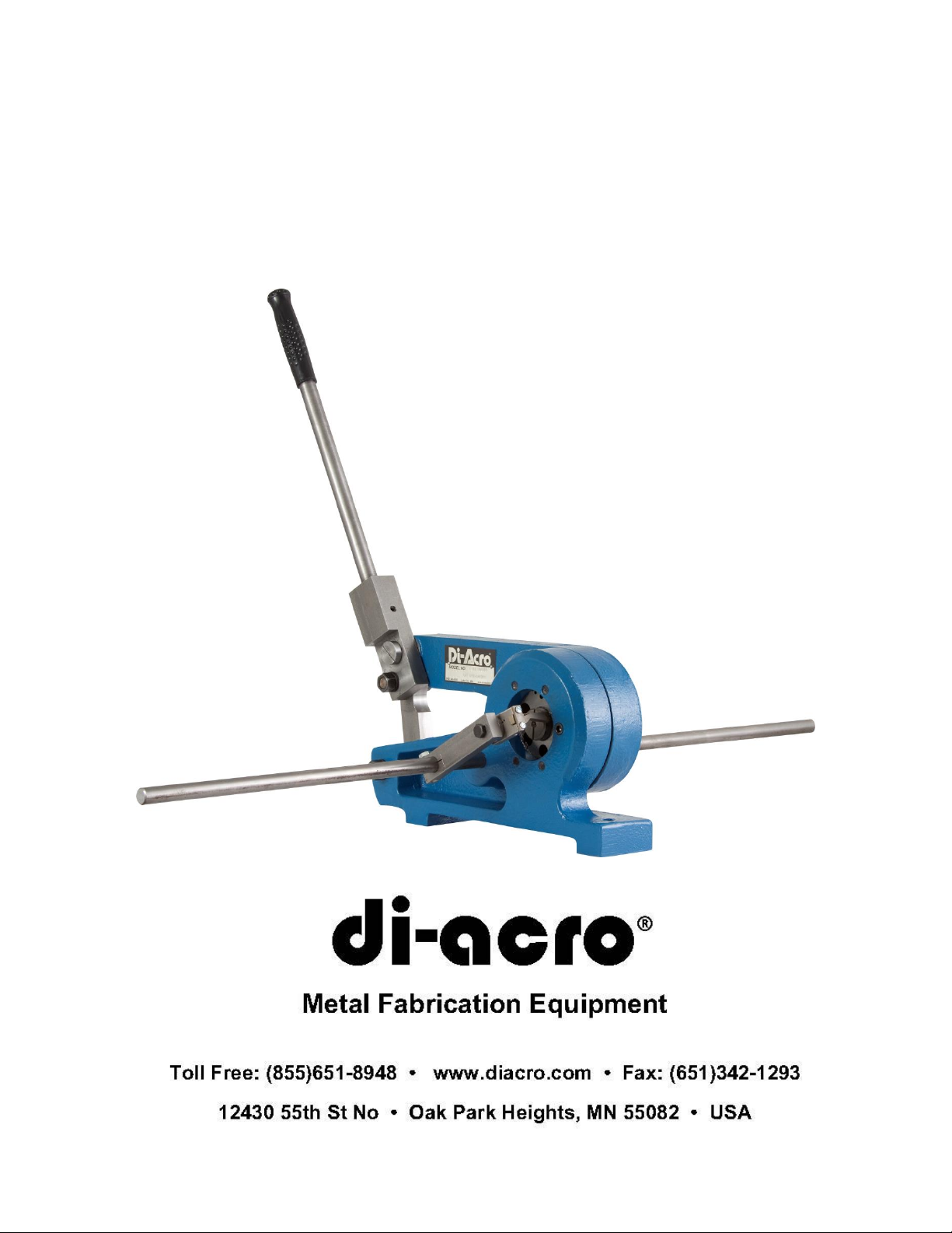
DI-ACRO
#2 ROD PARTER
INSTRUCTION MANUAL

REV. E 9/12
2
TABLE OF CONTENTS
A. SAFETY INFORMATION PG. 3
B. SET-UP PROCEDURE PG. 3
C. MAINTENANCE PG. 3
D. TECHNICAL DATA PG. 4
E. REMOVING AND SHARPENING CUTTING HEADS PG. 4
#2 ROD PARTER BREAKDOWN AND PARTS LIST PG. 5-6
G. EJECT-O-MATIC GAUGE BREAKDOWN
AND PARTS LIST PG. 6-7
H. OPTIONAL STAND PG. 8
WARRANTY PG. 9

REV. E 9/12
3
A. SAFETY INFORMATION
Before Rod Parter is set up for operation, mount on work bench or
stand.
*IF ROD PARTER IS MOUNTED ON ITS OWN STAND, SECURE STAND TO
FLOOR.
B. SET-UP PROCEDURE
After Rod Parter is bolted to work bench or stand attach Handle to
Handle Holder. Install gauge Rod to Base and attach Eject-o-matic
Gauge as follows:
Set Gauge Arm so bolt lines up with Pivot Bolt of Rod Parter, then
adjust gauge for desired hole and length of piece. Only the lower
portion of the rod should contact gauge.
C. MAINTENANCE
Apply grease to fitting in Center Stud Bolt periodically.

REV. E 9/12
4
D. TECHNICAL DATA
There are nine holes in the cutting head of the #2 Rod Parter from 1/8”
to 1/2” in diameter graduated in steps of 1/16” (all holes are
approximately .005” oversize). Cutting heads of heavy alloy tool steel,
properly hardened and precision ground, assure a high degree of
accuracy and are reversible to offer double service. They are easily
removed for re-sharpening and can be quickly reinstalled. Three heavy
duty bronze bearings in the multiple leverage system provide extreme
ease of operation and long, trouble-free performance.
Standard Equipment
Short handle for “parting-off” light material is standard equipment.
Optional Equipment
Long handle for “parting-off” heavier material is optional equipment.
Eject-o-matic Gauge
Set of cutting heads for “parting-off” round cold rolled bar stock.
Rod Parter Accessories
Cutting head for “parting-off” square, rectangular, hexagon and other
special shaped bar stock, call to request special quotation.
E. REMOVING AND SHARPENING CUTTING HEADS
The cutting heads on the Rod Parter are designed so that their positions
can be reversed to give extra cutting service before sharpening. To do
this, turn cutting heads around so that the outside sections are back to
back.
To Remove Cutting Heads
1. Remove Center Pivot Bolt, Link Bolt and disengage Upper Casting.
2. Remove socket head screws in both the Upper and Base Casting,
and tap out Cutting Heads.
To Sharpen Cutting Heads
Grind them approximately .002” to .005” on a surface grinder or return
them to the factory for this service.

REV. E 9/12
5
#2 ROD PARTER PARTS BREAKDOWN
8080810-080
Parts List
ITEM
PART NUMBER
DESCRIPTION
QTY
2
8150650-110
NAMEPLATE
1
3
8400470-100
CENTER STUD BOLT
1
4
20A0516C1104
SCREW-SOCKET 5/16-18X1-1/4
4
5
8080110-200
UPPER CASTING
1
6
8080470-100
LONG STUD BOLT
2
7
030-6503001
CAUTION PLATE
1
8
8080141-070
EJECTOMATIC TRIGGER ASSY
(SEE PG 6 & 7 FOR PARTS
BREAKDOWN)
1
9
8080141-001
STOP ROD
1
10
8100120-901
DIE ROD PARTER
2
11
8080110-800
SPACER
1
12
8470410-200
MALE/FEMALE LOCKNUT
1
13
8690100-200
DRIVE FITTING
1
14
19A0308X1102
PIN-DOWEL 3/8X1-1/2
8
15
8080110-100
BASE
1

REV. E 9/12
6
Parts List –Continued
ITEM
PART NUMBER
DESCRIPTION
QTY
16
30X0102C
NUT-FULL 1/2X13
3
17
23A0516C0508
SCREW-SSS 5/16-18X5/8
1
18
8310410-100
BEARING
3
19
8993120-800
HANDLE HOLDER
1
20
8080120-101
LINK
1
21
8300470-100
SHORT STUD BOLT
1
22
8080120-800
100-0142-M
HANDLE ARM (SHORT)
HANDLE GRIP
1
1
23
8000120-871
HANDLE ARM ASSY(LONG)
(OPTIONAL)
1
24
62X0102
WASHER-LOCK 1/2(NOT
SHOWN) GOES BEHIND
ITEM 16
3
25
23A0516C1000
SCREW-SSS 5/16-18X1
1
26
21A0104C1104
SCREW-HHCS 1/4-20X1-1/4
(NOT SHOWN)
1
27
31X0104C
NUT-JAM (NOT SHOWN)
1
F. EJECT-O-MATIC GAUGE
Greatly increases production output as it allows the three separate
operations of gauging, parting and ejecting to be obtained in a single
working cycle.
The Eject-O-matic Gauge is especially valuable when cutting lengths
under six inches but is equally as useful “parting” stock of longer
lengths. It is supplied as standard equipment on the hand operated rod
parter.

REV. E 9/12
7
Eject-O-Matic Gauge Breakdown
ITEM
PART NUMBER
DESCRIPTION
QTY
1
8200141-001
EJECTOMATIC SPACER
1
2
8300141-001
EJECTOMATIC ARM
1
3
21A0516C1000
SCREW-HEX 5/16-18X1
2
4
8400141-001
EJECTOMATIC HOLDER
1
5
8500141-001
EJECTOMATIC TRIGGER
1
6
20B0X06C0104
SCREW-BHSCS #6-32X1/4
2
7
8600141-001
EJECTOMATIC PLATE
1
8
8080510-402
SPRING
1

REV. E 9/12
8
G. OPTIONAL STAND
Part Number: 8230110-900
Stand Dimensions: 20” WIDE, 15” DEEP, 33-1/4” HIGH
CALL DI-ACRO FOR PRICE AND AVAILABILITY
Fasteners needed to attach Rod Parter to the stand are the following:
Fasteners to attach stand to floor are not included.
PART NUMBER
DESCRIPTION
QTY
21A0102C2102
SCREW-HHCS 1/2-13X2-1/2
2
61X0102
WASHER-FLAT 1/2
2
30X0102C
NUT-FULL 1/2-13
2

REV. E 9/12
9
Warranty & Limitation of Liability
Defective parts, of a product manufactured by DI-ACRO, will be replaced or repaired at
no charge for twelve (12) months following delivery to the original purchaser. Labor is
included for the first 90 days. This warranty becomes void when products have not
been used according to instructions furnished by DI-ACRO, nor does it cover any
altered parts or unauthorized repairs. We cannot be responsible for the cost of repairs
made or attempted outside of our factory. All other warranty claims are made FOB our
plant, providing such items(s) is returned freight prepaid to our plant for examination.
This warranty does not apply to parts, components or systems not manufactured by DI-
ACRO. These products are covered instead by the existing warranties, if any, of their
manufacturers. Normal service items with a reasonable life expectancy of less than one
year are warranted only to the extent of the reasonable life under normal use and
service.
Authorization must be obtained from DI-ACRO before returning parts or equipment to
the factory. DI-ACRO will satisfy this warranty by replacing the product or refunding the
purchase price upon receipt, inspection and defect identification.
DI-ACRO’s liability under this warranty shall not exceed the amount paid for the product.
THIS IS DI-ACRO’S SOLE WARRANTY IN LIEU OF ALL OTHER WARRANTIES,
EXPRESS OR IMPLIED, WHICH ARE HEREBY EXCLUDED, INCLUDING IN
PARTICULAR ALL WARRANTIES OF MERCHANTABILITY, FITNESS OR ANY
LOSS, DAMAGE OR EXPENSES DIRECTLY OR INDIRECTLY RELATED TO THE
USE OF ITS PRODUCT OR FROM ANY OTHER CAUSE OR FOR CONSEQUENTIAL
DAMAGES INCLUDING, WITHOUT LIMITATION, LOSS OF TIME AND LOSS OF
PRODUCTION.
IT IS EXPRESSLY UNDERSTOOD THAT DI-ACRO IS NOT RESPONSIBLE FOR
DAMAGE OR INJURY CAUSED TO OTHER PRODUCTS, MACHINERY, PROPERTY
OR PERSONS BY REASON OF THE USE OF ITS PRODUCTS.
cCopyright 2012
Table of contents
Other Di-Acro Tools manuals


Popular Tools manuals by other brands

Powerfix Profi
Powerfix Profi PKRS 1.5 A1 operating instructions

Sealey
Sealey AK962EV.V2 instructions

Parkside
Parkside PLPRS 1.5 B3 operating instructions

OpticsPlanet
OpticsPlanet OPMOD Survival Series product manual

BGS technic
BGS technic 3065 instruction manual

EINHELL
EINHELL Druckluftset Profi 11011 Original operating instructions


