DI BLASI R7-E Installation guide

OPERATION
AND
MAINTENANCE
Ò
Mod. R7-E
FOLDING MOTORBIKE

INDEX
Brakes (adjustments) 5.3
Cable (throttle) 5.4
Diagnosis 8
Expanding pulley (disassembling) 6.2
Folding 3
Fuel 4.2
Handlebar hinge (adjustement) 5.2
Handlebar hook (adjustment) 5.1
Headlamp (adjustment) 5.6
Horn 4.6
Idling 5.5
Lights 4.5
Magnetowheel 5.8
Reduction unit (disassembling) 6.1
Riding 4.4
Running in 4.1
Servicing 5.9 - 7
Spark plug 5.7
Technical specifications 1
Tyre pressure 4.3
Turn signal lamps 4.7
Unfolding 2
Wheels (disassembling) 6.1 - 6.3
Wiring diagram 5.10
6
- manufacturer & model DI BLASI M1
- single cylinder, two stroke
- bore 39 mm
- stroke 41,8 mm
- cylinder capacity 49.9 cc
- compression ratio 8,65 : 1
- maximum power 0,92 KW at 3700 RPM
- maximum torque 2,56 Nm at 3000 RPM
- spark plug BOSCH W7A
or AC43F
or N.G.K. B6HS
- carburetor DELL'ORTO SHA 14-12
main jet size: 53
choke tube: 12 mm
- fuel regular gasoline
with 2% of 2 stroke oil
- primary drive V-Belt variator
ratios: min 1:1,577
max 1:3,736
- secondary drive timing belt
ratio 22/102 = 1 : 4,636
- starting foot kick starter
Engine
1. SPECIFICATIONS
Dimensions
- Open:
Overall length 128 cm (50“)
Wheel base 93 cm (37“)
Width 58 cm (23“)
- Folded:
Length 78 cm (30“)
Width 36 cm (14“)
Height 61 cm (24“)
6Unladen mass 32 kg (69 Lbs)
6Rim size (front & rear) 5“
6Tyre size (front & rear) 4.00 - 5“
6Brakes drum diameter 90 mm (front & rear)
6Electrical equipment 12V - 65W
6Tank capacity 3 litres (3 quarts)
6Fuel consumption 50 km/lt (approx)
(130 mls per gallon)
6Maximum speed 50 km/h (30 mph)
6Seating capacity 1
6
Notice
Pictures and drawings of this manual have the sole
aim to illustrate the operations described herein:
however, they may not correspond exactely to your
vehicle.

2. TO UNFOLD THE VEHICLE
When the vehicle is folded, it stands up alone. Rotate the handlebar on the stem hinge until it is
locked by the hook.
Important Caution: make sure that both springs
which pull the hook are functionning properly and
that the hook itself is properly positioned (sec.5.1).
When rotating the handlebar, do not turn the wheel,
because the muffler pipe is still in the way. .
Holding the handlebar with the left hand, with the
right hand pull and then backwards the rear edge of
the saddle until...
... the frame is locked automatically by the hook
located on its right side under the saddle.
Place the vehicle on its stand.
Unfold the foot rest. Unfold the rearview mirror.
Before riding, read sec. 4.4.
Fig. 1 Fig. 2 Fig. 3 Fig. 4
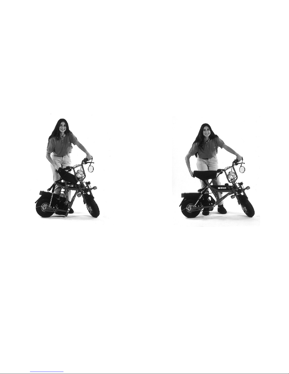

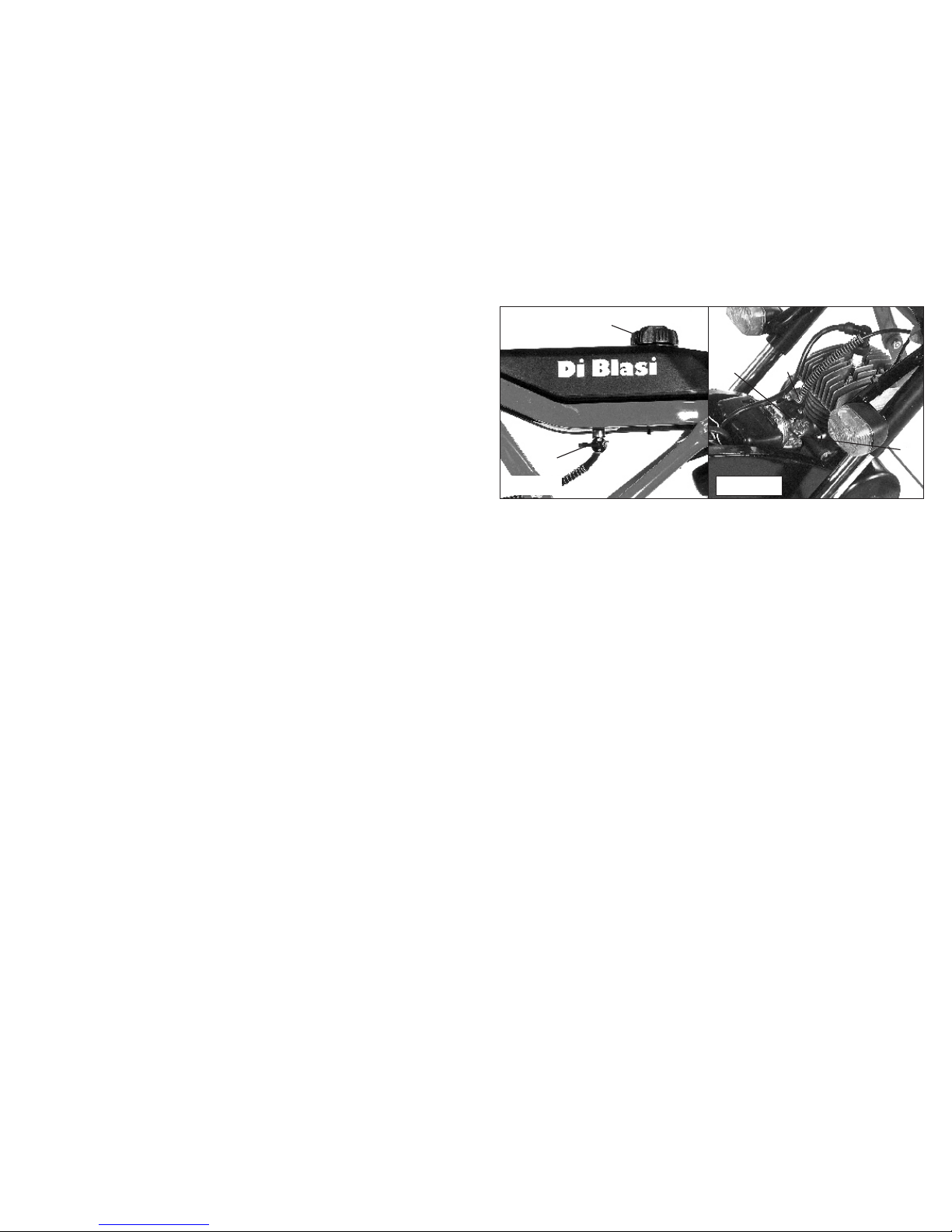
Close the fuel tap (A-fig.9) by turning the lever to
OFF (pointing backword) . Closing of the tank air
vent hole is automatic. If you need to store the
moped on it’s side, run the engine until it consumes
all the fuel in the carburetor reservoir.
3. TO FOLD THE VEHICLE
Fold the rearview mirror.
Push the vehicle off its stand.
Turn the steering fully to the right.
Release the frame hook located on the right side
under the saddle and .....
......push the rear edge of the saddle forward until it
is almost at the same level with the filler cap.
Unhook the handlebar and lower it.
Fold the foot rest.
The vehicle stands up alone.
Fig. 5 Fig. 6 Fig. 7 Fig. 8
6Open the throttle slightly, by twisting the right
handlebar grip (B-fig.12).
6Start the engine by pushing down the kick starter
lever with the foot.
6A few seconds after that the engine as started,
release the choke to its open position by opening
the throttle completely and immediately closing
it. Prolonged operation with the choke on will
cause spark plug fouling. Use caution to insure
that the vehicle is on its stand and apply the
front brake while the throttle is opened
completely.
6Get on the vehicle assuming the riding position.
6With the throttle in the closed position, apply the
rear brake before pushing the vehicle off its
stand.
6Once started, the vehicle is driven at the desired
speed solely by use of the twist grip throttle (B-
fig12)
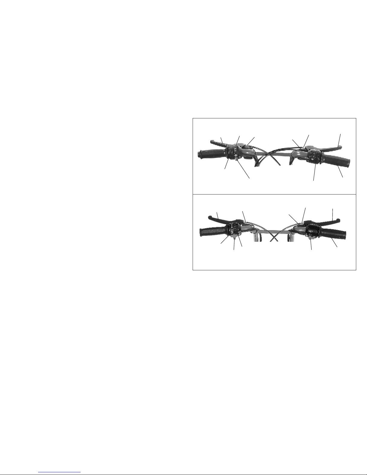
4.6 Horn
The push button for the horn (color blue) is located on
the left side of the handlebar (fig.12 - E).
4.7 Turn signal lamps
The switch (T) for the turn signal lamps is located:
6In European mopeds: on the right of the
handlebar (fig.12 EU);
6In USA mopeds: on the left of the handlebar
(fig.12 US);
4 OPERATING INSTRUCTIONS
4.1 Running-in
During the first 500 km (300 mls), use a mixture of
regular gasoline with 4% two stroke oil and do not
operate at more than 3/4 throttle. At about 500 km
(300 mls) check all bolts and nuts for proper tightness
and tighten the cylinder head nuts at 10 Nm torque.
4.2 Fuel
After the first 500 km (300 mls) use a mixture of regu-
lar gasoline with 2% two stroke oil.
CAUTION: an improper mixture or just fuel without
oil will cause damages and voids all warranties.
4.3 Tyre pressure
Front: 1,2 atm (18 psi)
Rear: 1,8 atm (26 psi)
4.4 Riding
6Place the vehicle on its stand and make sure that
the rear wheel is rised from the ground.
6Open the fuel tap placed under the tank turning
the lever straight down to ON or straight up to
reserve (fig.9).
6If the engine is cold, push down the choke lever
located on the carburetor (A-fig.10).
6In USA mpeds only: move the red switch (S-fig.
12 US) located on the right side of the handlebar
into RUN position.
6To slow down, close the throttle and, if necessary,
apply the brakes.
6The vehicle is equipped with two brakes. The
front wheel brake is controlled by the lever on
the right side of the handlebar (C-fig 12). The
rear wheel brake is controlled by the lever on the
left side of the handlebar (D-fig.12). Under
normal stopping conditions, use the rear brake
only. Use the front brake only if necessary and in
conjunction with the rear brake: in any case very
softly and with extreme caution. Hard, sudden
use of the front brake can be very dangerous.
6With the throttle in the closed position, the engine
will run while the vehicle is stationary.
6To stop the engine:
- In European mopeds: close the throttle and
press the red button (S) located on the left
side of the handlebar (fig.12 EU).
- In USA mopeds: close the throttle and move
the red switch (S), located on the right side of
the handlebar, into STOP position (fig.12 US).
4.5 Lights
The switch for the lights is located on the left side of
the handlebar (L-fig.12)
6In European mopeds: the three positions of the
switch correspond to: off, low, high beam.
6In USA mopeds: lights are always switched on
when engine runs. The three positions of the switch
correspond to: low beam, high beam, flashing.
Fig. 9 Fig. 10 Fig. 12 EU
Fig. 12 US
B
B
A
A
C
B
C
D
E
F
FG
L
S
T
B
C
D
E
FF
G
LST
6Open the throttle slightly, by twisting the right
handlebar grip (B-fig.12).
6Start the engine by pushing down the kick starter
lever with the foot.
6A few seconds after that the engine as started,
release the choke to its open position by opening
the throttle completely and immediately closing
it. Prolonged operation with the choke on will
cause spark plug fouling. Use caution to insure
that the vehicle is on its stand and apply the
front brake while the throttle is opened
completely.
6Get on the vehicle assuming the riding position.
6With the throttle in the closed position, apply the
rear brake before pushing the vehicle off its
stand.
6Once started, the vehicle is driven at the desired
speed solely by use of the twist grip throttle (B-
fig12)
4.6 Horn
The push button for the horn (color blue) is located on
the left side of the handlebar (fig.12 - E).
4.7 Turn signal lamps
The switch (T) for the turn signal lamps is located:
6In European mopeds: on the right of the
handlebar (fig.12 EU);
6In USA mopeds: on the left of the handlebar
(fig.12 US);
4 OPERATING INSTRUCTIONS
4.1 Running-in
During the first 500 km (300 mls), use a mixture of
regular gasoline with 4% two stroke oil and do not
operate at more than 3/4 throttle. At about 500 km
(300 mls) check all bolts and nuts for proper tightness
and tighten the cylinder head nuts at 10 Nm torque.
4.2 Fuel
After the first 500 km (300 mls) use a mixture of regu-
lar gasoline with 2% two stroke oil.
CAUTION: an improper mixture or just fuel without
oil will cause damages and voids all warranties.
4.3 Tyre pressure
Front: 1,2 atm (18 psi)
Rear: 1,8 atm (26 psi)
4.4 Riding
6Place the vehicle on its stand and make sure that
the rear wheel is rised from the ground.
6Open the fuel tap placed under the tank turning
the lever straight down to ON or straight up to
reserve (fig.9).
6If the engine is cold, push down the choke lever
located on the carburetor (A-fig.10).
6In USA mpeds only: move the red switch (S-fig.
12 US) located on the right side of the handlebar
into RUN position.
6To slow down, close the throttle and, if necessary,
apply the brakes.
6The vehicle is equipped with two brakes. The
front wheel brake is controlled by the lever on
the right side of the handlebar (C-fig 12). The
rear wheel brake is controlled by the lever on the
left side of the handlebar (D-fig.12). Under
normal stopping conditions, use the rear brake
only. Use the front brake only if necessary and in
conjunction with the rear brake: in any case very
softly and with extreme caution. Hard, sudden
use of the front brake can be very dangerous.
6With the throttle in the closed position, the engine
will run while the vehicle is stationary.
6To stop the engine:
- In European mopeds: close the throttle and
press the red button (S) located on the left
side of the handlebar (fig.12 EU).
- In USA mopeds: close the throttle and move
the red switch (S), located on the right side of
the handlebar, into STOP position (fig.12 US).
4.5 Lights
The switch for the lights is located on the left side of
the handlebar (L-fig.12)
6In European mopeds: the three positions of the
switch correspond to: off, low, high beam.
6In USA mopeds: lights are always switched on
when engine runs. The three positions of the switch
correspond to: low beam, high beam, flashing.
Fig. 9 Fig. 10 Fig. 12 EU
Fig. 12 US
B
B
A
A
C
B
C
D
E
F
FG
L
S
T
B
C
D
E
FF
G
LST

5 CHECKS AND ADJUSTMENTS
5.4 Throttle cable
To take up slacks in the throttle cable, adjust device B
- fig. 10 or G - fig. 12 .Tighten the lock nut after
adjustment.
5.5 Idling
To adjust the engine idling speed (fig.10):
6increasing: turn clockwise
6decreasing: turn the screw C counterclockwise
5.6 Head lamp
The head lamp inclination may be adjusted after
loosening the two mounting screws.
5.7 Spark plug
The gap of the electrodes should be 0,3 0,4 mm.
Clean the spark plug with the wire brush located in
the tool box.
Tithening torque of the spark plug on the cylinder
head: 28 Nm
5.8 Magnetowheel
The spark plug ignition is provided by an electronic
magnetowheel.
The spark advance is 22° 24° corresponding to 2,30
2,45 mm before the top dead center.
the screw C
÷
÷
÷
5.9 Nuts and bolts
All nuts and bolts are equipped with locking
devices (lock nuts, self locking nuts, lock
washers). Nevertheless, check the tightening
periodically.
5.10 Wiring harness
See electric diagram:
6In the European mopeds: fig. 22 EU
6In the USA mopeds: fig. 22 US
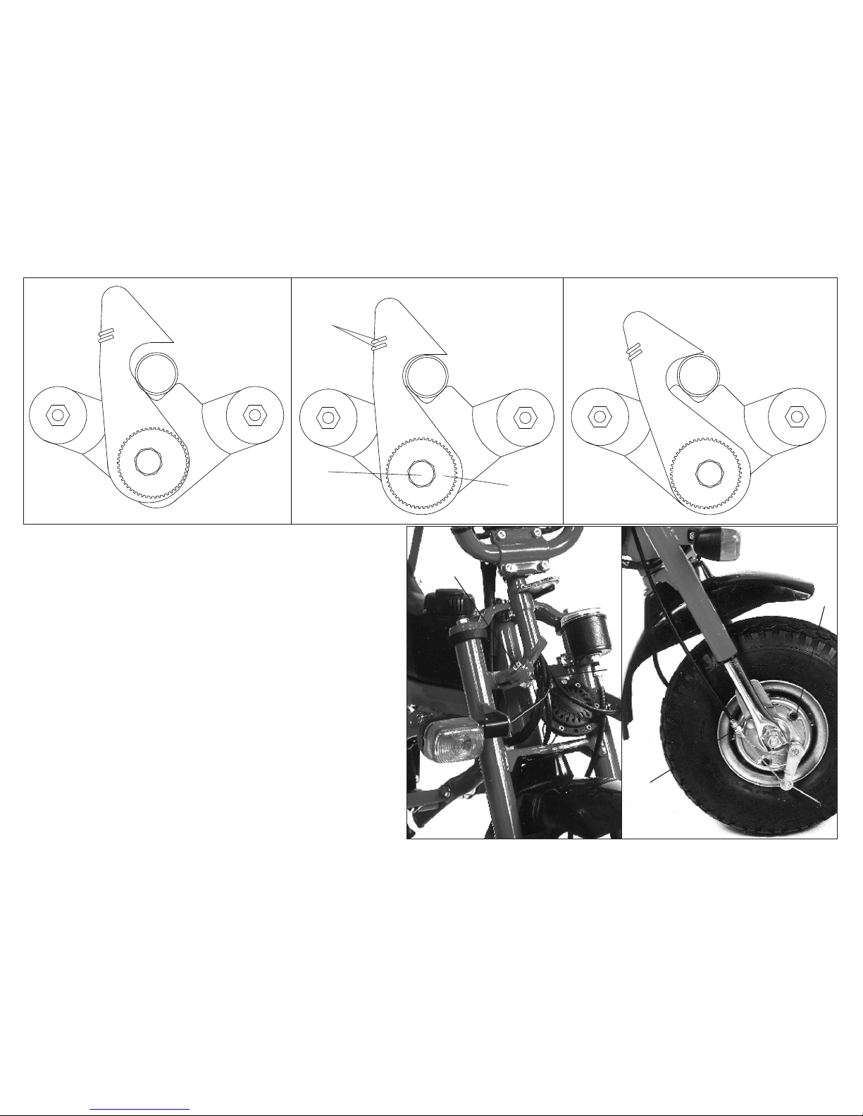
5.1 Handlebar hook
The locking hook is secured by two springs (A-
fig.14). Before riding, be sure that both springs are
working properly.
The correct position of the hook is illustrated in
fig.14. If the hook goes out of adjustment (as
illustrated in fig.13 and 15), readjust as follows:
6loosen the screw (B) for a fraction of turn;
6turn the knurled eccentric ring (C) until the
hook assumes the position indicated in fig. 14;
6tighten again the screw (B)
5.2 Handlebar hinge
If the handlebar hinge feels loose, tighten the lock nut
(A-fig. 16) to take out the slack without
overtightening.
The handlebar stem must still swivel reasonable easy.
5.3 Brakes
The brakes may be adjusted at the handbrake levers
(F-fig. 12) and at the brake backing plate (A-fig.17)
After each adjustment tighten the correspondent nut.
With the brake levers in their normal position, the
wheels must turn freely.
To check the brake lining thickness, remove the
rubber plugs located in the brake backing plates (B-
fig. 17).
Fig. 13 Fig. 14 Fig. 15
A
BC
NO NOOK
Fig. 16 Fig. 17
A
A
B
B
5 CHECKS AND ADJUSTMENTS
5.4 Throttle cable
To take up slacks in the throttle cable, adjust device B
- fig. 10 or G - fig. 12 .Tighten the lock nut after
adjustment.
5.5 Idling
To adjust the engine idling speed (fig.10):
6increasing: turn clockwise
6decreasing: turn the screw C counterclockwise
5.6 Head lamp
The head lamp inclination may be adjusted after
loosening the two mounting screws.
5.7 Spark plug
The gap of the electrodes should be 0,3 0,4 mm.
Clean the spark plug with the wire brush located in
the tool box.
Tithening torque of the spark plug on the cylinder
head: 28 Nm
5.8 Magnetowheel
The spark plug ignition is provided by an electronic
magnetowheel.
The spark advance is 22° 24° corresponding to 2,30
2,45 mm before the top dead center.
the screw C
÷
÷
÷
5.9 Nuts and bolts
All nuts and bolts are equipped with locking
devices (lock nuts, self locking nuts, lock
washers). Nevertheless, check the tightening
periodically.
5.10 Wiring harness
See electric diagram:
6In the European mopeds: fig. 22 EU
6In the USA mopeds: fig. 22 US
5.1 Handlebar hook
The locking hook is secured by two springs (A-
fig.14). Before riding, be sure that both springs are
working properly.
The correct position of the hook is illustrated in
fig.14. If the hook goes out of adjustment (as
illustrated in fig.13 and 15), readjust as follows:
6loosen the screw (B) for a fraction of turn;
6turn the knurled eccentric ring (C) until the
hook assumes the position indicated in fig. 14;
6tighten again the screw (B)
5.2 Handlebar hinge
If the handlebar hinge feels loose, tighten the lock nut
(A-fig. 16) to take out the slack without
overtightening.
The handlebar stem must still swivel reasonable easy.
5.3 Brakes
The brakes may be adjusted at the handbrake levers
(F-fig. 12) and at the brake backing plate (A-fig.17)
After each adjustment tighten the correspondent nut.
With the brake levers in their normal position, the
wheels must turn freely.
To check the brake lining thickness, remove the
rubber plugs located in the brake backing plates (B-
fig. 17).
Fig. 13 Fig. 14 Fig. 15
A
BC
NO NOOK
Fig. 16 Fig. 17
A
A
B
B

7. SERVICING
7.1 Every 1000 km (600 miles)
6Lubricate with grease the speedometer drive
(B-fig.18) through the lubricating nipple.
6Clean the air filter and the carburetor;
7.2 Once a year
6Lubricate the cables (brakes,throttle,
speedometer) and the frame articulations with
a drop of light oil.
6Clean the starting gears and lubricate with
grease.
6Replace the rubber fuel line: after one year the
rubber tube becomes brittle and cracked and
this can cause fire when the engine is hot.
6.2 Expanding pulley / clutch (fig.18)
For disassembling:
6
6unscrew screw (T);
For assembling:
6add a drop of loctite (medium grade) in
the screw (T)
6tighten the screw (T) with a pneumatic
screwdriver or with a socket wrench while
holding the magnetowheel
For spare parts order see Fig. 21
Unscrew the three bolts (B1 - B2 - B3)
holding the belt guard.
6 DISASSEMBLIES
6.1 Rear wheel - reduction unit (fig. 18-19)
6Unscrew the lock nut of the screw (A) and
then the screw (A) at the bottom of the left
shock absorber.
6Rotate the left shock absorber on its top end so
to keep it removed from the belt guard.
6Unscrew the three bolts (B1 - B2 - B3) holding
the belt guard.
6Disconnect the brake cable from the brake
backing plate on the right hand side of the
wheel;
6While pulling forward the reduction unit arm
(C), remove the primary belt (D);
6Remove the screw head (G) through the hole
(H);
6Unscrew the nuts (L) holding the wheel to the
fork;
6Remove the wheel assembly from the fork;
6Disconnect the spring (M) at its end (N);
6Remove the arm (C) from its rotation pin
together with the timing belt;
6Remove the tap washer (P), unscrew the four
screws (Q) and remove the crown wheel.
For reassembling, the previous steps are to be
carried out in on the reverse.
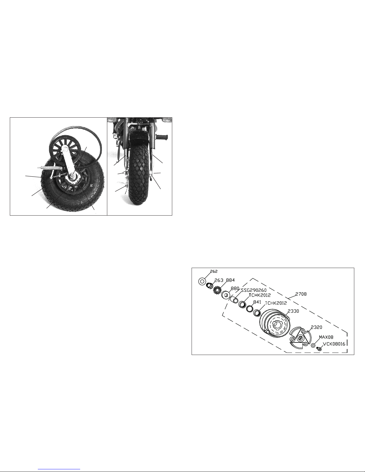
6.3 Front wheel (fig.20)
6disconnect the brake cable at the brake
backing plate (A);
6disconnect the speedometer cable at the
speedometer drive (B);
6Unscrew the clamping nuts (C).
CAUTION: when reassembling the wheel,do not
turn (screwing or unscrewing) the fork tips (D).
Fig. 21
Fig. 18
B1
B2
B3
A
C
D
E
L
F
GH
T
Fig. 19 Fig. 20
N
M
QP
L
AB
CC
D
D
7. SERVICING
7.1 Every 1000 km (600 miles)
6Lubricate with grease the speedometer drive
(B-fig.18) through the lubricating nipple.
6Clean the air filter and the carburetor;
7.2 Once a year
6Lubricate the cables (brakes,throttle,
speedometer) and the frame articulations with
a drop of light oil.
6Clean the starting gears and lubricate with
grease.
6Replace the rubber fuel line: after one year the
rubber tube becomes brittle and cracked and
this can cause fire when the engine is hot.
6.2 Expanding pulley / clutch (fig.18)
For disassembling:
6
6unscrew screw (T);
For assembling:
6add a drop of loctite (medium grade) in
the screw (T)
6tighten the screw (T) with a pneumatic
screwdriver or with a socket wrench while
holding the magnetowheel
For spare parts order see Fig. 21
Unscrew the three bolts (B1 - B2 - B3)
holding the belt guard.
6 DISASSEMBLIES
6.1 Rear wheel - reduction unit (fig. 18-19)
6Unscrew the lock nut of the screw (A) and
then the screw (A) at the bottom of the left
shock absorber.
6Rotate the left shock absorber on its top end so
to keep it removed from the belt guard.
6Unscrew the three bolts (B1 - B2 - B3) holding
the belt guard.
6Disconnect the brake cable from the brake
backing plate on the right hand side of the
wheel;
6While pulling forward the reduction unit arm
(C), remove the primary belt (D);
6Remove the screw head (G) through the hole
(H);
6Unscrew the nuts (L) holding the wheel to the
fork;
6Remove the wheel assembly from the fork;
6Disconnect the spring (M) at its end (N);
6Remove the arm (C) from its rotation pin
together with the timing belt;
6Remove the tap washer (P), unscrew the four
screws (Q) and remove the crown wheel.
For reassembling, the previous steps are to be
carried out in on the reverse.
6.3 Front wheel (fig.20)
6disconnect the brake cable at the brake
backing plate (A);
6disconnect the speedometer cable at the
speedometer drive (B);
6Unscrew the clamping nuts (C).
CAUTION: when reassembling the wheel,do not
turn (screwing or unscrewing) the fork tips (D).
Fig. 21
Fig. 18
B1
B2
B3
A
C
D
E
L
F
GH
T
Fig. 19 Fig. 20
N
M
QP
L
AB
CC
D
D

8 DIAGNOSIS
8.2 The engine does not run normally
The reason can be:
6One of the reasons listed in sec. 8.1
6Carbon deposit at the piston and cylinder
head, at the cylinder exhaust port, in the
exhaust pipe;
6The spark plug or the cylinder head or the
induction manifold are not tightened.
8.3 Fouling at the electrodes
The reason can be a too poor carburation:
6Clean the carburetor, the cylinder exhaust
port, the exhaust pipe;
6Tighten the spark plug,the cylinder head, the
induction manifold;
6Make sure that fuel is a mixture of regular
fuel with 2% oil.
8.4 Jamming of the expanding pulley
Disassemble and clean.
8.5 Jamming of the reduction unit
Replace the V-belt.
8.1 The engine does not start
6Check if the fuel is not reaching the carburetor
because:
- The tank is low on fuel: place fuel tap in
reserve position (lever pointing up) and
then refuel;
- The fuel tap is closed;
- The fuel line is clogged (by an air bubble,
for instance);
- The carburetor or air filter is dirty.
6Check the ignition:
- With the spark plug removed and resting
with its metal portion lying on the fins of
the cylinder, check whether there is a
spark between the electrodes by
depressing the kick starter manually.
- Check whether the spark plug is dirty (in
this case clean it thoroughly) and check
whether the gap of the electrodes is
correct (0.3 0.4 mm );
- Check the spark plug cable and replace
if it is broken or poorly insulated;
- Check the electric wiring (see diagram
fig. 22). Make sure that the ground
connection between the engine and the
frame is efficient.
÷
A Orange
B White
C Blue
G Yellow
H Gray
M Brown
N Black
P Pink
R Red
V Green
X Ye l l o w -
Green
Z Violet
HRS Horn Switch
BLS Blinker Light Switch
ESS Engine Stop Switch
SLS Stop Light Switch
FRB Front Right Blinker
STB Stabilizer
COL Coil (2003)
MGN Magnetowheel (2002)
LGS Light Switch
HRN Horn
HLT Head Light
FLB Front Left Blinker
BLK Blinking Device
RLB Rear Light Blinker
RRB Rear Light Blinker
HRS
ESS
SLS
BLS
HRN
HLT
FLB FRB
STB
COL
MGN
RLB RRB
TLT
SLT
LGS
CAVPZ R
XRG
NM
H B
Fig. 22EU
BLSSLS LGS
HSS
HRN
HLT
ESS
FLB FRB
STB
COL
MGN
BLK RLB RRB
TLT
SLT
Z C A R HG V X
N B P
Fig. 22US

Cod. 699 - R7 - Inglese - Ed 11.97
Table of contents


