DIADEM DiaSafe Single User manual


2
Table of contents
1Description of symbols 3
2Introduction – General description 4
2.1 Single anchoring points 4
2.1.1 DiaSafe®Single 4
2.2 Line wire-rope system 4
2.2.1 DiaSafe® Line Multi 4
2.2.2 DiaSafe®Glide 4
2.2.3 Possibility of combinations with RoofX®systems 4
3Safety instructions 5
3.1 General safety instructions 5
3.2 Application 6
4Manufacturer’s responsibility, warranty 7
4.1 General terms of warranty 7
4.2 Expected lifetime 8
5System design, components 9
5.1 DiaSafe®Single anchoring points 9
5.1.1 DiaSafe®Single 9
5.1.2 DiaSafe®Single / Anchor point components 9
5.1.3 Recommended carabiner to connect to the system 9
5.2 DiaSafe®Glide wire-rope system 10
5.2.1 DiaSafe®Glide 10
5.2.2 DiaSafe®Glide / Wire-rope system components 10
5.3 DiaSafe®Line Multi wire-rope system 12
5.3.1 DiaSafe®Line Multi 12
5.3.2 DiaSafe®Multi / Wire-rope system components 12
5.3.3 Recommended carabiner to connect to the system 13
5.4 DiaSafe® systems accessories 13
6Load bearing structure and ballast layer 14
6.1 Load bearing structure 14
6.2 Ballast material 14
6.2.1 Installation of the system in the case of ballast materials with various layer thicknesses 16
6.2.2 Uniform layer thickness 16
6.2.3 Varying layer thickness 16
7Information on system installation and usage 17
8System installation and annual inspection information 17
8.1 System installation and annual inspection 17
8.2 Information regarding required free fall height 17
9Documentation 18
10 Technical data 18
11 Installation 19
11.1 Presses usable for pressing 19
11.1.1 Pressing jaw and lining to be used for pressing 19
12 Disposal 19
13 Manufacturer, certification 20
3
1 Description of symbols
Pictograms in the Technical Manual have the following meanings:
System users are obliged to carefully read this manual and the related service book,
and shall closely follow all relevant safety regulations and user requirements listed
herein.
Utilization modes of the safety system based on the number of persons using the
system simultaneously: (1+1 persons are considered as standard case.)
- SOLO System: In case of use by 1+1 persons, the system can be used even
by two persons simultaneously, but the fall arresting function can be
guaranteed only if the falls take place at different times.
- DUO System: In case of permanent simultaneous use by 2 persons, the fall
arresting function is also guaranteed if the falls happen at the same time.
The fall arresting system can be used by more users simultaneously, so that maximum
1+1 users can be connected into each second span.
Usage of personal protective equipment is required (in accordance with EN 361 and EN
363). Manufacturer’s prescriptions of the given equipment shall be observed.
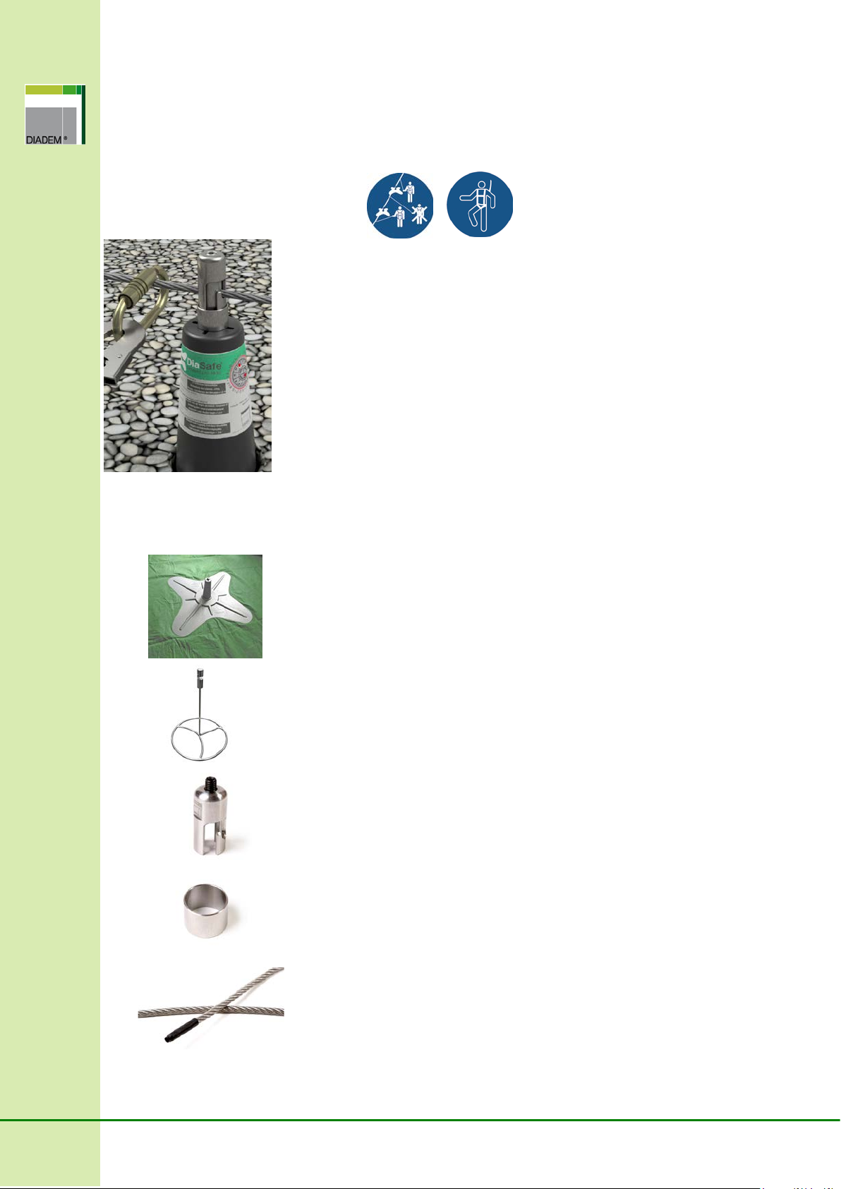
Danger, which could lead to severe injury or death.

4
2 Introduction – General description
2.1 Single anchoring points
2.1.1 DiaSafe®Single
The DiaSafe®Single was developed as a safety technical system working as a single anchoring point
based on the standards EN 795:2012 (Type A) and CEN/TS 16415:2013, for the simultaneous catch
of 2persons, in case of max. 5° roof angle, permanently secured by layering sequence. The
anchoring point can be used solely with personal protective equipment defined according to EN
363:2008.
2.2 Line wire-rope system
2.2.1 DiaSafe® Line Multi
The DiaSafe®Line Multi was developed as a horizontal wire-rope safety technical system based on
the standards EN 795:2012 (Type C) and CEN/TS 16415:2013, for the simultaneous catch of max.
1+1 persons, in every second post space, in case of max. 5° roof angle, permanently secured by
layering sequence. The anchoring point can be used solely with personal protective equipment
defined according to EN 363:2008.
2.2.2 DiaSafe®Glide
The DiaSafe®Glide was developed as a horizontal wire-rope safety technical system with traveller,
working based on the standards EN 795:2012 (Type C) and CEN/TS 16415:2013, for the
simultaneous catch of 2 persons, in case of max. 5° roof angle, permanently secured by layering
sequence. The anchoring point can be used solely with personal protective equipment defined
according to EN 363:2008.
2.2.3 Possibility of combinations with RoofX®systems
All types of DiaSafe® Glide and RoofX®Glide safety systems (RoofX®-C Glide, RoofX®-W/T Glide,
DiaSafe®Glide, Wall-Fix®Glide) can be combined with each other in order to create a continuous
wire-rope system that can be fixed to various surfaces. In such cases the system functions and
number of permitted users shall be adjusted according to the least favourable conditions.
The highest manufacturing quality of the fall arrester anchoring systems is guaranteed by the
manufacturer’s quality management system complying with the standards ISO 9001:2009 and ISO
14001:2005, from the high-level product development through the selection of high-quality base
materials up to the final quality control.

5
3 Safety instructions
3.1 General safety instructions
The safety system may only be installed and used by appropriately trained, competent persons who
are familiar with the safety system in accordance with this Techincal Manual and the Installation
Guide.
The system user must be familiar and comply with the local, and labour safety regulations.
The system may only be used by people who:
are trained in the use of PPE (Personal Protective Equipment).
are physically and psychologically fit (health restrictions such as heart and circulatory
problems, medication, alcohol consumption, etc. reduce user safety).
understood and accepted the possibilities, restrictions and risks of using the protective
equipment.
The rescue of anyone who may have fallen down must be provided on site.
Before works begin, measures must be taken to ensure that no objects can fall down from the
workspace. The area under the workspace (pavement, ...etc.) is to be kept clear.
If after the acceptance of the safety system, renovation work is undertaken in its immediate vacinity,
it must be established that this renovation has no impact on the safety of the installed safety system!
In case of doubt, the installer or the manufacturer must be consulted.
After being subjected to the stress of fall, the entire safety system is to be taken out of operation and
inspected by a qualified professional.
The installed safety system must not be altered in any way.
It is forbidden to use the safety system as a lightning protection system. Components of the lightning
protection system statically should not load the safety system. The system is not allowed to be used
as an earth cable. Relevant regulations must be complied with.
Never hang loads on the safety system that are not approved in this manual, and never use it as an
alpinist suspension point.
The system is never to be used as alpinist anchoring points. The system shall not be loaded with
any further weight different from its original purpose.
The fall prevention anchoring systems can be installed and inspected only by specialists in
possession of a required certificate authorising them for the given system, and specialists of the
competent authorities or inspectorates.
A basic tenet of the effective operation of the fall protection anchoring system in the long term is
regular maintenance - at least every 12 months in the manner prescribed by the manufacturer.
It is forbidden to use the system until it has been inspected and completely or partially replaced if the
system has fulfilled its function!
If the maintenance is not carried out regularly, the system may be used exclusively at the
responsibility of the owner/maintainer.
The timing of inspections recommended by the manufacturer in the instructions of the installed
system (in individual cases) may also depend on the local legal requirements, on the frequency of
use, and on local conditions (e.g. chemical damage, frequent lightning, etc.).
The DiaSafe®system may be extended only through the use of original accessories, developed by
the manufacturer of the system. The installation and use of parts or products from other
manufacturers, even if their appearance is very similar, is strictly prohibited.
The installer should make sure that the receiving structure is able to bear the load what comes with
the system installation. If there is any doubt, consult with a structural engineer.

6
The DiaSafe®fall protection anchoring system may be installed and used only according to the
manufacturer’s guidelines in the Technical Manual.
If the system has fulfilled its fall arrest function, following a fall, the system must be immediately
withdrawn from use. An immediate inspection must be performed before the system is used again.
The system must be replaced entirely or partially depending on the findings of the inspection.
If the Technical Manual is lost, or the Service Manual is completed or seriously damaged, get in
touch with your distributor.
3.2 Application
In order to protect lives the Technical Manual should be read carefully, and the included
manufacturer’s notices and instructions must be observed, especially before first use of the
system. The Service Manual does not replace the Technical Manual. You should thoroughly study
the Technical Manual before starting to use the system.
The minimum free space necessary under the edge is calculated as follows: Deformation of the
anchor device in case of stress + manufacturer’s specification of the PPE (Personal
Protective Equipment) used, including deflection of the cable + body height + 1m safety
margin.
For installations higher than 1000 m above sea level, the distance between the posts will decrease
by 30%, while the wire-rope sagging will increase by 30%.
In heavy snowfall, the roof surface in the area of the fall protection system must be kept clear, so
that the snow can not affect the undisturbed functioning of this system.
Proper use of the individual components, including the PPE must be ensured, sincet he
effectiveness of the fall prevention system is otherwise not guaranteed.
System checks should be carried out at least once in every 12 months. Check interval durations
depend on relevant regional regulations, system use frequency, as well as local conditions (e.g.
chemical hazards).
Attachment to the fall protection system is completed with a carabiner and must be used with a
PPE in accordance with standards EN 361 (safety harness) and EN 363 (fall arrest system).
If the system will be used with a direct connection (a carabiner) or a traveller made by another
manufacturer according to EN 362 as long as the traveller doesn’t run through the column head-
special care must be taken during the coupling. The required distance for the couplins is max.15
cm.
In case of using personal protective equipment according to EN 360 or EN 365-2 special care must
be taken, and the properties is the equipment needed to taken account in the calculations.
ATTENTION! For horizontal use, only such connecting elements can be used which are designed
for this purpose and tested for the respective edge type (sharp edges, trapeziodal sheet, steel
griders, concrete, etc.).
Do not use fall arrest systems if wind speeds exceed normal parameters according to local safety
regulations!
DiaSafe®systems should only be used in a frosted environment if they have been installed in
unfrosted conditions or if at least one unfrosted period has elapsed between installation and first
use. If safe use of the system in frost is not guaranteed, it must not be used.
Do not use fall arrest systems if wind speeds exceed normal parameters.
The fall protection system must not be used by children or pregnant women.
In the EN 795 standard an installation documentation has had to be made since 2012 for every
anchoring system. This documentation must include detailed information about the following: location,
company carrying out the installation, installer responsible, system installed. Also there must be a
Delivery/receipt record completed (it is found in the Service Manual), which verifies that the
installation has been performed professionally in accordance with standards. Furthermore, there must
be drawn up a construction plan, which shows the places of the anchoring points and the steps of
7
installation must be photographed as well. Special care must be taken with elements of the anchoring
system which are going to be covered after the installation. If, on a given location, there are separate
roof areas and different types of anchoring systems are installed, a distinct documentation must be
made for each roof area and each system.
4 Manufacturer’s responsibility, warranty
Manufacturer's responsibility covers faulty products, unless the fault occurred as a result of
inappropriate use. Manufacturer shall only replace faulty or damaged components. No further claims
(indirect or property damage) are acknowledged by the manufacturer.
Because of the unknown site conditions, the manufacturer assumes no responsibility for the
warranty about damage caused by diversion fom the Technical Manual (improper use, incorrect
installation or other reasons).
A major prerequisite of long-term fall protection system operation is regular maintenance as
prescribed by the manufacturer. Should maintenance steps fail to be executed in due time, then the
system can only be used for own risk. Should any damage or accident happens on an unchecked
system the manufacturer's responsibility shall terminate.
DiaSafe®systems can be extended using original accessories developed exclusively by the
manufacturer. Should any components or products of any other manufacturer be installed or used in
the system, manufacturer's responsibility and guarantee terminate immediately.
Should the system not be installed or assembled by the manufacturer or a contractor authorised for
installation, the manufacturer shall accept no claims, other than for faulty products.
Should a fall occur, the system must be discarded and it is PROHIBITED to use it any longer!
System use can only be resumed after an official interim inspection. In accordance with the
inspection, relevant system components or the whole system must be overhauled or replaced. As
long as the distraint or the inspection is not carried out, the manufacturer is not liable for the use of
the system any longer.
Manufacturer shall cease to take any further responsibility for the system in the following cases:
damage and alterations due to environmental conditions, normal wear and tear, misuse and an
aesthetic alteration.
Particular attention has been paid to producing these instructions. However it is not possible to show
all the potential versions and these instructions do not therefore claim to be exhaustive. DIADEM®
APP GmbH shall not be liable for any usage or application error, which may arise from the
misinterpretation of the methods shown here.
4.1 General terms of warranty
For the DiaSafe®fall protection anchoring systems range, we undertake a General Manufacturer’s
warranty of 60 months, valid from the day of the sale of the product by Manufacturer.
The warranty does not cover:
Any loss of time, inconvenience, administrative costs or any other consequential damages
suffered by the owner/maintainer as a consequence of a malfunction under warranty.
Repair or replacement of spare parts, due to the following causes:
Wear and tear from normal use.
Damage or alteration due to negligence or improper use.
Activated fall arrest function, requiring replacement.
Any modification of the system, or of any part thereof, without the manufacturer’s approval.
Uses not intended or expressly prohibited by the manufacturer.
8
Damage caused by the user’s physical condition or health (with special regard to the weight
limit: 130kg/person) and thus improper use.
Damage caused by the owner/maintainer’s failure to adequately maintain, service or repair
any part of the system.
Other causes, such as: damage due to extreme environmental impact; natural wear and tear,
aesthetic alteration, etc.
Loss of warranty rights, including, among others:
Damage occurring following incorrect installation of the product, or installation not following
the guidelines.
Loss of function and other faults due to improper use.
Deterioration, structural damage, loss of function of the installed product due to external
impact.
Loss of function or structural damage due to natural causes (lightning strike, etc.).
Evidence of damage caused by unauthorised and/or non-professional repair, mounting, or
impact.
4.2 Expected lifetime
The DiaSafe®safety systems maximum lifetime is 10 year from the date of correct installation – In
case of the intended use, optimal condition, and without any visible damage.
The real working life may be, in normal use conditions, considerably longer without major degradation
affecting the basic requirements for works. These provisions are based upon the current state of the
art and the available knowledge and experience. The indications given as to the working life of the
construction product cannot be interpreted as a guarantee, but are regarded only as a means for
expressing the expected economically reasonable working life of the product.

9
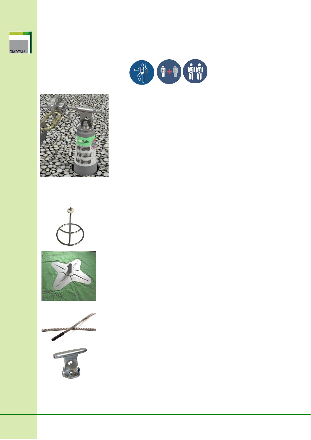
5 System design, components
5.1 DiaSafe®Single anchoring points
5.1.1 DiaSafe®Single
Post structure: DS Single anchor post + DS amoeba-shaped damping
plate with ballasting mat (3x3 m)
Properties: no need to break through the layering sequence of the
roof insulation to perform the installation
Load direction: 360° (horizontal)
Material: stainless steel 1.4404 (anchor post),
glass-fibre reinforced plastic (amoeba-shaped damping
plate)
Fixation: specified ballast material (detailed in Point 6)
Standard height: 300 mm
Custom sizes can be ordered (300-1400 mm)
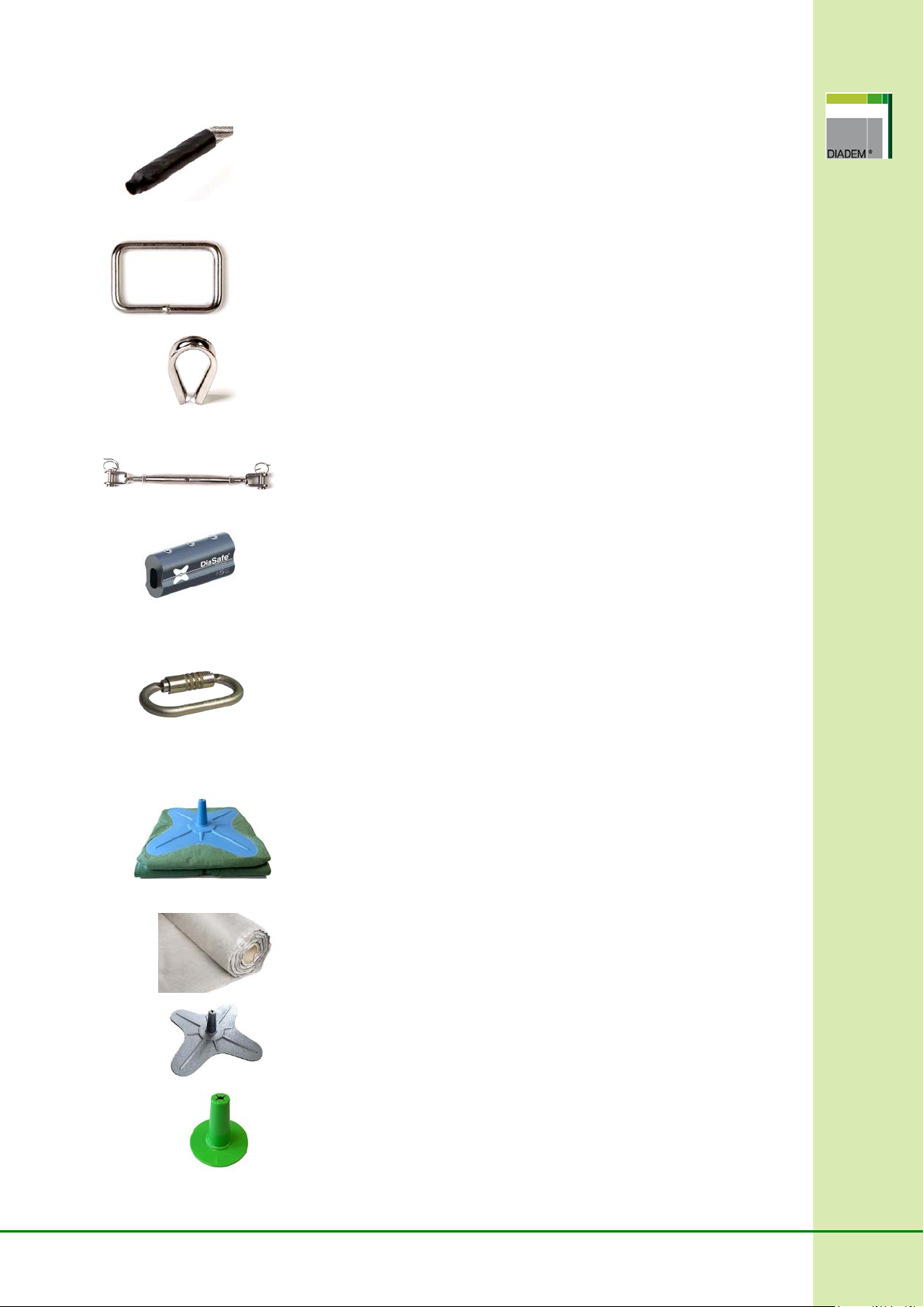
5.1.2 DiaSafe®Single / Anchor point components
DS Single anchor post
Product No.: 100369
Material: Stainless steel 1.4404
Size: 300 mm x 250 mm
DS amoeba-shaped damping plate with ballasting mat (3x3m)
Product No.:100302
Material: Glass-fibre reinforced plastic
Size: 3x3m
5.1.3 Recommended carabiner to connect to the system
Applied standard: EN 362:2013
Max. diameter: ∅12 mm
10
5.2 DiaSafe®Glide wire-rope system
5.2.1 DiaSafe®Glide
Post structure: DS Glide anchor post + DS amoeba-shaped damping
plate with ballasting mat (3x3 m)
Properties:no need to break through the layering
sequence of the roof to perform the installation
Load direction: 360° (horizontal)
Material: stainless steel 1.4301 (anchor post),
stainless steel 1.4408 (head),
glass-fibre reinforced plastic (amoeba-shaped damping
plate)
Fixation:specified ballast material (detailed in Point 6)
Min. distance of posts: 1.5 m
Optimal distance of posts: 7.5 m (max. 8 m)
Standard height: 300 mm
5.2.2 DiaSafe®Glide / Wire-rope system components
DS post
Product No.: 100520
Material: Stainless steel 1.4301
Size: Ø250mm x 285mm
DS amoeba-shaped damping plate with ballasting mat (3x3m)
Product No.: 100302
Material: Glass-fibre reinforced plastic
Size: 3x3m
DS stainless steel wire-rope
Product No.: 100268
Material: Stainless steel 1.4404
Diameter: Ø 8mm (7 × 19 strands)
Tensile strength: F = 33.4 kN
DS Glide head Kit
Product number: 130937
Material: Stainless steel 1.4408
Attached: M12 self-locking nut, flat washer, spring washer

11
DS Swaged square end
Product No.: 100354
Material: Stainless steel 1.4404
DS DiaGlider-Fix (without carabiner)
Product No.: 100471
Material: Stainless steel
Application: Placed on the wire, not detachable,
it can be used by max. 2 people simultaneously.
DS Wire-rope terminating shrinkable tube
Product No.: 090845
Size: Ø 9 mm
DS Swaged turn buckle (in case of closed system)
Product No.: 100356
Material: Stainless steel 1.4404
Adjustable length: 325 - 400 mm
DS Holder (optional: for system beginning, ending and T-branching)
Product No.: 100513
Material:Stainless steel 1.4301
DS Cable Thimble (optional)
Product number:100279
Material:Stainless steel 1.4404
Size: 58 x 38 mm
DS Multi-turn buckle (optional)
Product number:100259
Material: Stainless steel 1.4404
Adjustable length: 290 - 415 mm
DS Multi clamp (optional)
Product No.: 100470
Material: aluminium (body), stainless steel (screw)
DS DiaGlider with carabiner (optional)
Product No.: 100350
Material: Stainless steel
12
5.3 DiaSafe®Line Multi wire-rope system
5.3.1 DiaSafe®Line Multi
Post structure: DS Multi anchor post + DS amoeba-shaped damping
plate with ballasting mat (3x3 m)
Properties: no need to break through the layering sequence
of the roof to perform the installation
Load direction: 360° (horizontal)
Material: Stainless steel 1.4404 (anchor post),
glass-fibre reinforced plastic (amoeba-shaped
damping plate)
Fixation: specified ballast material (detailed in Point 6)
Min. distance of posts: 1.5 m
Optimal distance of posts: 7.5 m (max. 8 m)
Standard height: 300 mm
Custom sizes can be ordered (300-1400 mm)
5.3.2 DiaSafe®Multi / Wire-rope system components:
DS amoeba-shaped damping plate with ballasting mat (3x3m)
Product No.: 100302
Material: Glass-fibre reinforced plastic
Size: 3x3m
DS Multi anchor post
Product No.: 100316
Material: Stainless steel 1.4404
Size: Ø250mm x 300mm
DS Multi fixing head
Product No.: 100318
Material: Stainless steel 1.4404
Size: Ø 28 x 60 mm
Attached: DIN912 M10x20 mm set screw
DS Multi retainer ring
Product No.: 100319
Material: Stainless steel 1.4404
Size: Ø 31.5 mm x 23 mm
DS stainless steel wire-rope
Product No.: 100268
Material:Stainless steel 1.4404
Diameter:Ø 8 mm (7 × 19 strands)
Tensile strength: F = 33.4 kN
13
DS Wire-rope terminating shrinkable tube
Product No.: 090845
Size: Ø 9 mm
DS Multi rectangular anchoring ring
Product number:100317
Material: Stainless steel 1.4404
Size: 57.5 mm x 87.5 mm
Material thickness: Ø 8 mm
DS Cable Thimble
Product number:100279
Material: Stainless steel 1.4404
Size: 58 x 38 mm
DS Multi-turn buckle
Product number:100259
Material: Stainless steel 1.4404
Adjustable length: 290 - 415 mm
DS Multi clamp
Product No.: 100470
Material: aluminium (body), stainless steel (screw)
5.3.3 Recommended carabiner to connect to the system
Applied standard: EN 362:2013
Max. diameter: ∅12 mm
5.4 DiaSafe®systems accessories
DS amoeba-shaped damping plate with ballasting mat (5x5m)
Product No.: 100368
Material: Glass-fibre reinforced plastic
Size: 5x5m
DS Auxiliary ballasting mat
Product No.: 320317
Material: Polypropylene
DS Auxiliary rising attachment
Product No.: 100304
Material: Glass-fibre reinforced plastic
DS Signal cone
Product No.: 100373
Material: Glass-fibre reinforced plastic
14
6 Load bearing structure and ballast layer
6.1 Load bearing structure
DiaSafe®systems were tested and examined on a number of surface types and structures (roofs with
steel, reinforced concrete and wooden structure). Their performance is controlled on the most
prevailing waterproofing materials (bituminous, PVC, TPO or EPDM) and roof panes. The system is
applicable on any roof system which is able to bear the extra load originating from the installation and
use of the system.
Warning!
The system cannot be installed on substructure with grained or rolling structure (e.g.: gravel
or planting medium).
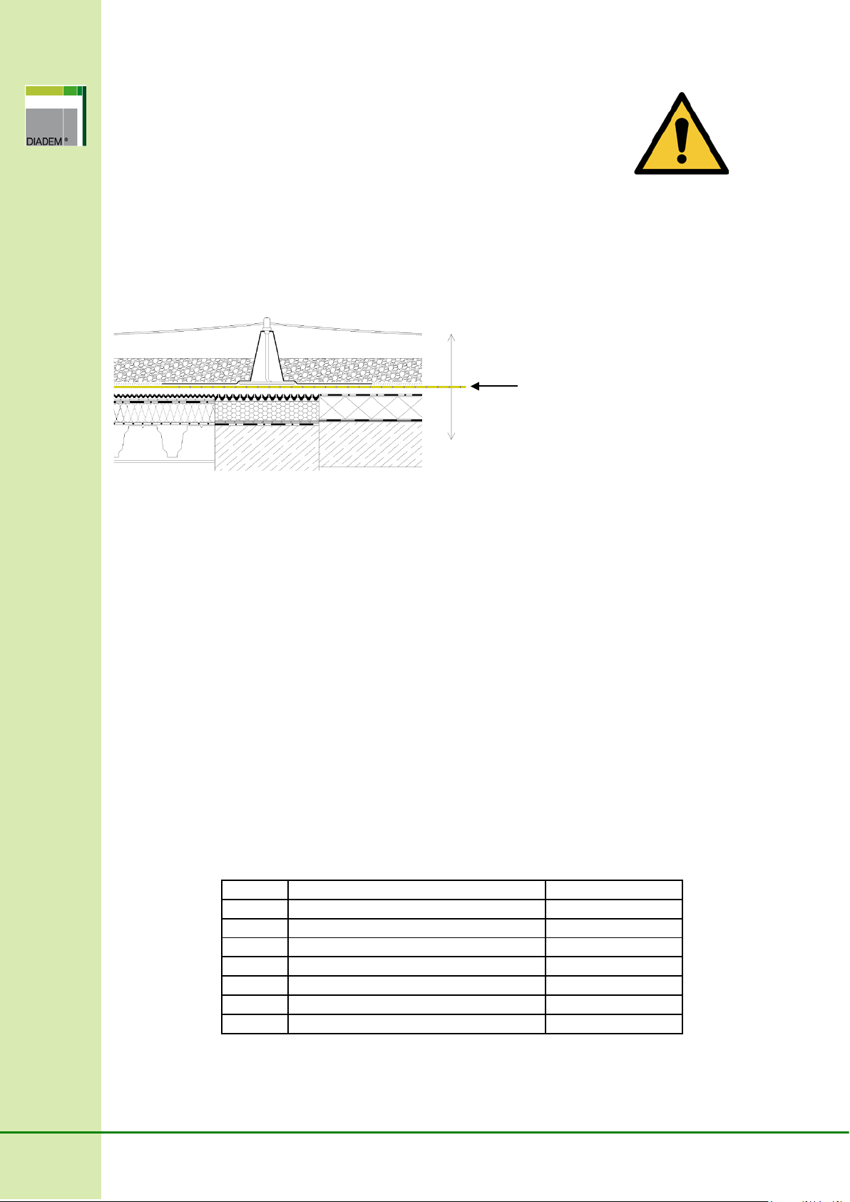
6.2 Ballast material
Stability of the system is ensured by the ballast layer which can be planting medium for green roof,
otherwise gravel surfacing or other bulk material. DiaSafe®anchoring points can be used on roofs with
maximum 5° slope angle.
It shall be ensured that the surface weight of the ballast layer in dry state on the entire surface
of the ballasting mat:
If the system is SOLO, i.e. its is used by 1+1 persons:
- should be 80 kg/m2at least when applying standard (3x3 m) ballasting mat
- or minimum 720 kg per post, if the system is used by 1+1 persons.
- thickness of the ballast layer is minimum 3 cm in any case
If the system is DUO, i.e. it is used by 2 persons:
- should be 200 kg/m2at least when applying standard (3x3 m) ballasting mat
- or minimum 1800 kg weight per post.
- thickness of the ballast layer is minimum 3 cm in any case
Solo
number of users
1+1
standard mat size
3x3 m
surface weight
80 kg/m2
total weight per post
720 kg
Duo
number of users
2
standard mat size
3x3 m
surface weight
200 kg/m2
total weight per post
1800 kg
VLF separation fabric

15
Standard mat sizes belonging to the anchor points is 9 m2(3×3 m) and optionally 25 m2(5×5 m),
respectively. The specified minimum ballast layer thickness of minimum 3 cm shall always be ensured.
When applying custom mat sizes, the minimum ballast surface weight shall be determined according to
the Technical Manual to which assistance is provided by the table series below:
Solo – 1+1 users
Duo - 2 users
If the surface of the ballasting mat shall be increased, application of an auxiliary ballasting mat is
required. If the surface of the ballasting mat shall be reduced for geometric reasons, the standard
ballasting mat must be folded back to the appropriate size or cut, but in this case, the minimum distance
of the mat measured from the centre point of the damping plate cannot be smaller than 50 cm at any
Mat
size Total
weight Surface
weight
Layer thickness:
gravel, sand
γ = 1600 kg / m³
Layer thickness:
planting medium
γ = 1000 kg / m³
Layer thickness:
planting medium
γ = 800 kg / m³
m2(m × m) kg kg/m2cm cm cm
4.0 (2 × 2) 720 180 10.5 18.0 22.5
6.0 (3 × 2) 720 120 7.0 12.0 15.0
9.0 (3 × 3) 720 80 5.0 8.0 10.0
12.0 (3 × 4) 720 60 min. 3.5 6.0 7.5
16.0 (4 × 4) 720 45 min. 3.0 4.5 6.0
20.0 (4 × 5) 800 40 min. 3.0 4.0 5.0
25.0 (5 × 5) 875 35 min. 3.0 3.5 4.0
30.0 (5 × 6) 900 30 min. 3.0 3.0 3.5
35.0 (5 × 7) 1050 30 min. 3.0 3.0 3.5
40.0 (5 × 8) 1200 30 min. 3.0 3.0 3.5
Mat size Total
weight Surface
weight
Layer thickness:
gravel, sand
γ = 1600 kg / m³
Layer thickness:
planting medium
γ = 1000 kg / m³
Layer thickness:
planting medium
γ = 800 kg / m³
m2(m × m) kg kg / m2cm cm cm
4.0 (2 × 2) 1800 450 28,5 45,0 56,5
6.0 (3 × 2) 1800 300 19,0 30,0 37,5
9.0 (3 × 3) 1800 200 12,5 20,0 25,0
12.0 (3 × 4) 1860 155 9,5 15,5 19,0
16.0 (4 × 4) 1920 120 7,5 12,0 15,0
20.0 (4 × 5) 1900 95 6,0 9,5 12,0
25.0 (5 × 5) 2000 80 min. 5,0 7,5 9,0
30.0 (5 × 6) 2400 80 min. 5,0 6,0 7,5
35.0 (5 × 7) 2800 80 min. 5,0 5,5 6,5
40.0 (5 × 8) 3200 80 min. 5,0 min. 5,0 6,0

16
point, and special attention shall be paid to the existence of the appropriate ballast weight. It is
prohibited to cut or damage the glass-fibre reinforced plastic in any way.
Warning!
Because the thickness of the ballast layer may change by time (people walk on it, it is eroded
by wind or rain etc.), the actual layer thickness must be controlled before each use by visual
inspection at least. The ballast layer must always cover the ballasting mat on the entire
surface. In case of inadequate layer thickness, additional ballast material is required.
The various types of ballast materials (substrate, gravel etc.) can be combined within one
system; in such a case uniform weight distribution of the mixed ballast materials shall be
ensured. For this help is provided by the marking placed on the anchor post of the damping
plate, which is described in detail in the Installation Guide.
6.2.1 Installation of the system in the case of ballast materials with various layer
thicknesses
Thickness of ballast material ≤ 20 cm Thickness of ballast material ≥ 20 cm
Layer thickness of the ballast materials on green roofs can be different. If thickness of the ballast layer
is maximum 20 cm or less, the system can be installed in the regular way. For larger layer thickness
the system can be installed using a custom size anchor post and DS auxiliary rising element. This
applies both for the wire-rope and single systems.
6.2.2 Uniform layer thickness
Basically, the uniform weight distribution of the ballast materials shall be ensured. Only the minimum
layer thickness shall be ensured. The top of the post of the DiaSafe®systems shall be at least 10 cm
above the surface of the ballast layer.
6.2.3 Varying layer thickness
Uneven ballast layer is permitted under observance of the load parameters.

17
7 Information on system installation and usage
- The system guarantees full-scale safety for the user, regardless of the sag of the wire.
- Sag of the wire may change during the lifetime of the system, e.g. due to the mounting actions,
thermal expansion or other dynamic effects. It is important that the DiaSafe®systems are not
anchored systems, the wire does not need to be entirely tight, on the contrary, overtight wires
originating from the incorrectly adjusted sag of the wire disadvantageously affect the efficiency and
durability of the anchoring system.
- If posts of the system are distorted due to the incorrect wire tension during or after the installation,
it means that the system was overstretched. The allowed distortion of the posts is 45° measured
from the vertical axis in any direction, but the side of the cone (from the point measured back
vertically 10 mm from the top of the cone to the bottom) as well as its bottom part shall remain
intact, they must keep their integrity.
- Such bending of a post due to mounting, thermal expansion or other dynamic effects means solely
an aesthetic change to the system, it cannot be subjected to manufacturer’s warranty procedure.
- The system is capable to accomplish its function even in the above cases.
- When using according to the respective intended use, the fixing element of post head of the Multi
system can be used - released and then fixed again - safely so many times on the occasion of the
mandatory check before maintenance, inspection and use, until no tear of a filament on the wire
can be experienced and the clamping bolt can be operated as intended.
8 System installation and annual inspection information
8.1 System installation and annual inspection
- For the commissioning of the system, the Service Manual and the handover protocol shall be
completed in compliance with the test criteria. The validating sticker shall be placed on the control
label.
- The annual inspection shall be documented in writing. The test criteria and detailed information are
included in the Service Manual. Based on the international guidelines and the manufacturer’s
instructions, the inspection shall be performed without test load.
8.2 Information regarding required free fall height
To appropriately fulfil the fall arresting function of the system it is required to consider the correct free
fall height both for planning and before being put into service. To consider this, assistance is provided
by the respective existing provisions.
Warning!
The system cannot fulfil any fall arresting function if the free fall height does not reach the
minimum of 6.25 m height which is to be corrected with the displacement of the anchor point in
any case.
18
9 Documentation
The manufacturer provides documentation for each DiaSafe®system attached and in digital,
downloadable form. The installed falling arrest system can be registered on the DIADEM®Online
registration interface. The Service Manual is prepared during registration.
Parts of the documentation:
Technical Manual (printed or downloadable)
Installation Guide (printed or downloadable)
Service Manual (furnished with individual serial number): (printed)
•Handover protocol
•Checking protocol
•Validating decal
Control label (printed)
At the annual inspection, the expert performing the inspection is obliged to place the control label
validating the appropriate state of the installed fall arresting system on the control label of the system.
Warning!
In lack of a validly filled and logged Service Manual and/or Online System Registration the state of the
system becomes uncontrolled and its functionality becomes uncontrollable. This completely excludes
the Manufacturer’s responsibility for eventual damages, faults or injuries.
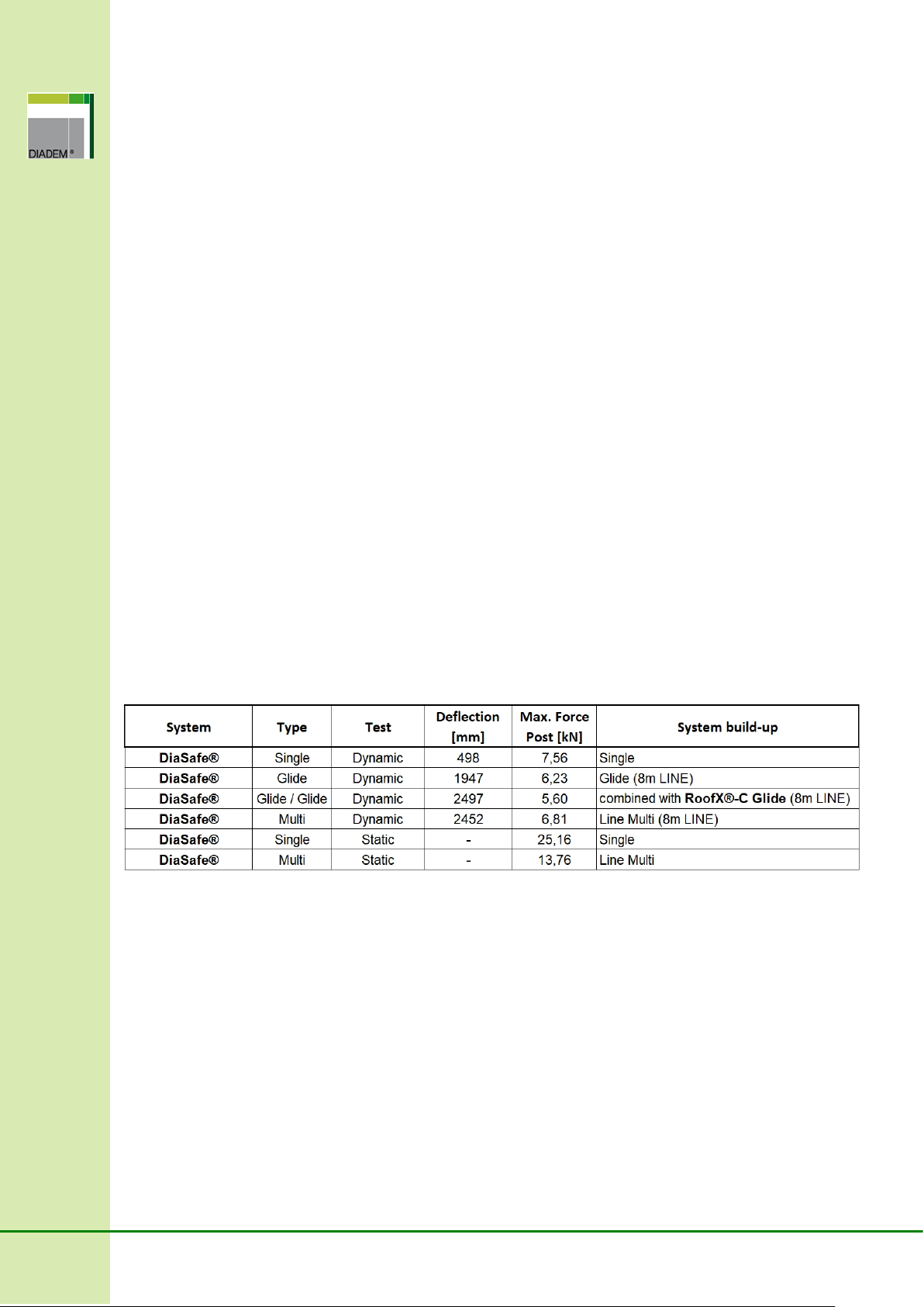
10 Technical data
Maximum forces and displacements (Temperature: 20 °C):
Sufficient clearance under the usage area shall be ensured in any case! Depending on the length of
wire the displacement may highly deviate from the data specified by the manufacturer.

19
11 Installation
11.1 Presses usable for pressing
The DiaSafe®anchoring systems were tested and approved by pressings produced by REMS radial
presses. The following models are suitable for pressing:
REMS Power-Press
REMS Power-Press SE
REMS Power-Press ACC
REMS Akku-Press
REMS Akku-Press ACC
These machines exert 36 kN pressing force which finally results in 100 kN force.
The manufacturer of the press must inspect all radial presses annually for appropriate operation. Make
sure that the used press has a certificate which verifies the inspection of the press within 12 months.
In addition to the above list, when using a different press, the use of presses with equivalent technical
specifications is required or they must be approved by the manufacturer of the DiaSafe®systems.
11.1.1 Pressing jaw and lining to be used for pressing
Pressing shall be performed with T12 press lining in any case, which fits in the standard pressing jaw.
T 12 press lining and pressing jaw
When using the press - with special attention to the lifetime of the pressing jaws and press linings - the
manufacturer’s specifications shall be observed. The T 12 press lining of the press was developed
specifically for the DiaSafe®Glide systems. This can be procured directly from the manufacturer of the
press or from the distributor or manufacturer of the DiaSafe®system.
All other installation information can be found in the product specific Installation Guide.
12 Disposal
Do not dispose of the fall protection system in the house waste. Following national requirements, gather
the used parts and dispose of them in an environmentally responsible fashion.

20
13 Manufacturer, certification
The DiaSafe®fall protection systems have been tested and certified by TÜV Austria Services GmbH.
Copyright:
DIADEM®, DiaSafe®and RoofX®are registered trademarks! This technical manual is the intellectual
property of the manufacturer, the use of its content in any form for business purpose, without the
previous authorization of the manufacturer is strictly forbidden.
DiaSafe®and RoofX®product manufacturer and distributor:
APP Kft.
H-9028 Győr
Fehérvári út 75.
Phone: +36 96 512 910
Fax: +36 96 512 914
info@diadem.com
www.diadem.com
APP Dachgarten GmbH
Jurastrasse 21
D-85049 Ingolstadt
Phone: +49 841 370 9496
Fax: +49 841 370 9498
info@grundach.com
www.diadem.com
This manual suits for next models
2
Table of contents


