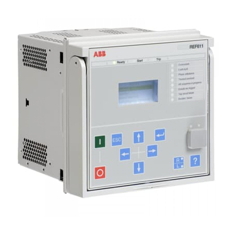
Edwards SIGA-REL Technical User manual

SIGA-REL Technical
Reference Manual
P/N 387348-EN • REV 007 • ISS 22SEP17

Copyright
© 2017 United Technologies Corporation
All rights reserved.
This document may not be copied in whole or in part or otherwise
reproduced without prior written consent from UTC Fire & Security,
except where specifically permitted under US and international
copyright law.
Document number: 387348-EN Revision: 007
Trademarks and
patents
The SIGA-REL name and logo are trademarks of United
Technologies Corporation.
Other trade names used in this document may be trademarks or
registered trademarks of the manufacturers or vendors of the
respective products.
FCC compliance
This equipment has been tested and found to comply with the limits
for a Class A digital device, pursuant to part 15 of the FCC Rules.
These limits are designed to provide reasonable protection against
harmful interference when the equipment is operated in a
commercial environment. This equipment generates, uses, and can
radiate radio frequency energy and, if not installed and used in
accordance with the instruction manual, may cause harmful
interference to radio communications.
You are cautioned that any changes or modifications not expressly
approved by the party responsible for compliance could void the
user’s authority to operate the equipment.
European Union
directives
The European directive “Waste Electrical and Electronic Equipment”
(WEEE) aims to minimize the impact of electrical and electronic
equipment waste on the environment and human health. For proper
treatment, recovery, and recycling, you can return the equipment
marked with this symbol to your local supplier upon the purchase of
equivalent new equipment, or dispose of it in designated collection
points. Further information can be found on the following website:
www.recyclethis.info.
European representative for manufacture: United Technologies
Corporation, Kelvinstraat 7, 6003 DH Weert, Netherlands.
Versions
Information in this manual applies to the following versions of
system development or configuration software.
EST2 Version 3.2
EST3 Version 3.6
QS-CU Version 1.8
Contact information
For contact information, see www.edwardsfiresafety.com.

SIGA-REL Technical Reference Manual i
Content
Important information ii
Related documents iv
Installation codes and standards iv
Chapter 1 Product design 1
Introducing the SIGA-REL 3
Fire suppression systems 4
Compatible panels and devices 6
Specifications 10
Application block diagrams 13
Fire suppression application 15
Release sequences 16
Chapter 2 Installation 19
Mounting the SIGA-REL 20
Setting abort mode and delay times 22
Reading the LEDs 24
Wiring the SIGA-REL 25
Warning notice placards 29
Chapter 3 Programming 33
Programming the SIGA-REL in the 2-SDU 35
Programming the SIGA-REL in the 3-SDU 39
Programming the SIGA-REL in the QS-CU 43
Chapter 4 Testing and troubleshooting 51
Code requirements for testing 52
System testing 52
SIGA-REL fault messages on EST2 panels 55
SIGA-REL fault messages on EST3 panels 56
SIGA-REL fault messages on QuickStart panels 57
Index 59

ii SIGA-REL Technical Reference Manual
Important information
Limitation of liability
To the maximum extent permitted by applicable law, in no event will UTCFS be
liable for any lost profits or business opportunities, loss of use, business
interruption, loss of data, or any other indirect, special, incidental, or
consequential damages under any theory of liability, whether based in contract,
tort, negligence, product liability, or otherwise. Because some jurisdictions do not
allow the exclusion or limitation of liability for consequential or incidental
damages the preceding limitation may not apply to you. In any event the total
liability of UTCFS shall not exceed the purchase price of the product. The
foregoing limitation will apply to the maximum extent permitted by applicable law,
regardless of whether UTCFS has been advised of the possibility of such
damages and regardless of whether any remedy fails of its essential purpose.
Installation in accordance with this manual, applicable codes, and the instructions
of the authority having jurisdiction is mandatory.
While every precaution has been taken during the preparation of this manual to
ensure the accuracy of its contents, UTCFS assumes no responsibility for errors
or omissions.
FCC compliance
This equipment can generate and radiate radio frequency energy. If the
equipment is not installed in accordance with this manual, it may cause
interference to radio communications. This equipment has been tested and found
to comply with the limits for Class A computing devices pursuant to Subpart B of
Part 15 of the FCC Rules. These rules are designed to provide reasonable
protection against such interference when this equipment is operated in a
commercial environment. Operation of this equipment is likely to cause
interference, in which case the user, at his own expense, will be required to take
whatever measures may be required to correct the interference.
Advisory messages
Advisory messages alert you to conditions or practices that can cause unwanted
results. The advisory messages used in this document are shown and described
below.

SIGA-REL Technical Reference Manual iii
WARNING: Warning messages advise you of hazards that could result in injury
or loss of life. They tell you which actions to take or to avoid in order to prevent
the injury or loss of life.
Caution: Caution messages advise you of possible equipment damage. They tell
you which actions to take or to avoid in order to prevent the damage.
Note: Note messages advise you of the possible loss of time or effort. They
describe how to avoid the loss. Notes are also used to point out important
information that you should read.

iv SIGA-REL Technical Reference Manual
Related documents
EST2 documentation
EST2 Installation and Service Manual (P/N 270186)
EST2 Network Supplement Manual (P/N 270894)
EST2 System Operations Manual (P/N 270188)
EST2 System Programming Manual (P/N 270187)
EST2 Installation Sheets (P/N 3100056)
2-SDU Online Help
EST3 documentation
EST3 Installation and Service Manual (P/N 270380)
EST3 System Operations Manual (P/N 270382)
EST3 Installation Sheets (P/N 3100051)
EST3 International Supplement Manual (P/N 270925)
3-SDU Help
QuickStart documentation
QS1 Technical Reference Manual (P/N 3100184)
QS4 Technical Reference Manual (P/N 3100186)
QuickStart Configuration Utility Online Help (P/N 7350047)
Signature Series
documentation
Signature Series Intelligent Smoke and Heat Detectors
Applications Bulletin (P/N 270145)
Signature Series Component Installation Manual (P/N 270497)
Serial Number Log Book (P/N 270267)
EST Publications: Speaker
and strobe documentation
EST Speaker Application Guide (P/N 85000-0033)
Handbook of Visual Notification Appliances for Fire Alarm
Applications (P/N 85001-0541)
Installation codes and standards
The Signature Series fire detection devices are designed to meet the
requirements of NFPA Standard 72, Underwriters Laboratories, Inc. Standard
864, and Underwriters Laboratories of Canada, Inc. Standard ULC S527. Other
related codes and standards are listed below. Information contained in this
document is intended to serve as a guide. Installation in accordance with the
instruction sheets (provided with Signature Series devices), applicable codes,
and the instructions of the AHJ is mandatory.

SIGA-REL Technical Reference Manual v
National Fire Protection
Association (NFPA)
NFPA 11 Low-Expansion Foam Systems
NFPA 12 Carbon Dioxide Extinguishing Systems
NFPA 11A Medium- and High-Expansion Foam Systems
NFPA 12A Halon 1301 Fire Extinguishing Systems
NFPA 13 Sprinkler Systems
NFPA 15 Water Spray Fixed Systems for Fire Protection
NFPA 16 Deluge Foam-Water Sprinkler and Foam-Water Spray
Systems
NFPA 17 Dry Chemical Extinguishing Systems
NFPA 70 National Electric Code
NFPA 72 National Fire Alarm Code
NFPA 2001 Standard on Clean Agent Fire Extinguishing
Systems
Underwriters Laboratories,
Inc. (UL)
QuickStart: UL 864 (9th Edition) Control Units for Fire-Protective
Signaling Systems
EST2: UL 864 (9th Edition) Standard for Control Units for Fire
Protective Signaling Systems
EST3: UL 864 (9th Edition) Standard for Control Units and
Accessories for Fire Alarm Systems
Underwriters Laboratories,
Canada (ULC)
ULC S527 Standard for Control Units for Fire Alarm Systems
Factory Mutual Research
Corporation (FM)
1011-1012 Deluge and Preaction Systems
European standards
73/23/EEC Low Voltage Directive
89/336/EE Electromagnetic Compatibility Directive (as amended
by 9/31/EEC)
EN 50130-4; 1995 Immunity requirements for Components of
Fire, Intruder, and Social Alarm Systems
EN 55022:1995 Limits and Methods of Measurement of Radio
Disturbance Characteristics of Information Technology
Components
Other requirements
Other requirements that affect the installation of this system
include:
•State and local building codes
•Instructions of the AHJ

vi SIGA-REL Technical Reference Manual

SIGA-REL Technical Reference Manual 1
Chapter 1
Product design
Summary
This chapter provides information for system designers. The SIGA-REL supports
a variety of fire suppression applications. These applications include sprinkler
systems and automatic fire extinguishing systems. The SIGA-REL works with
manual and automatic inputs. This chapter explains how the SIGA-REL fits into a
fire alarm system and how it behaves during fire alarms.
Content
Introducing the SIGA-REL 3
Description 3
Features 4
Fire suppression systems 4
Sprinkler systems 4
Automatic fire extinguishing systems 5
Compatible panels and devices 6
Panels 6
Software 6
Power supplies 7
Notification appliances 7
Solenoid control relays 7
Manual release stations 7
Abort stations 8
Service disconnect stations 8
Releasing solenoid valves 9
Listing agencies 9
Specifications 10
Application block diagrams 13
System overview 13
Preaction or deluge sprinkler systems 13

Chapter 1 Product design
2 SIGA-REL Technical Reference Manual
Automatic fire extinguishing systems 14
Fire suppression application 15
Release sequences 16
Automatic release sequence 16
Manual release sequence 18

Chapter 1: Product design
SIGA-REL Technical Reference Manual 3
Introducing the SIGA-REL
Description
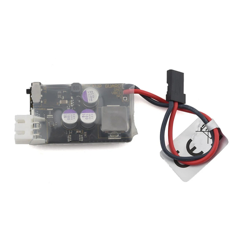
The SIGA-REL Releasing Module (Figure 1) is a Signature Series component
consisting of:
•Two supervised release circuits
•Two supervised prerelease circuits
•One supervised manual release input circuit
•One zone relay output (Form C contact)
•One supervised abort circuit for a normally-open abort switch
Figure 1: SIGA-REL Releasing Module
The SIGA-REL controls operations for deluge, preaction, and automatic fire
extinguishing systems. The release circuits control the release of gas and other
fire suppression agents by controlling the release solenoids. The release circuits
operate in unison and cannot be controlled separately.
Prerelease circuit 1 supports audible notification appliances that sound alert,
prerelease, and release signals. Prerelease circuit 2 supports visual notification
appliances.

Chapter 1 Product design
4 SIGA-REL Technical Reference Manual
Features
The SIGA-REL includes an intelligent microprocessor that supports:
•Deluge sprinkler operation
•Preaction sprinkler operation
•Automatic fire extinguishing operation
•Selectable abort modes
Fire suppression systems
Sprinkler systems
The SIGA-REL works with two types of sprinkler systems: deluge and preaction.
The primary difference between these systems is the type of sprinkler head (or
nozzle) that terminates the pipes. Table 1 outlines the Factory Mutual Research
Corporation (FM) requirements for deluge and preaction systems. FM also
requires FM Approved compatible release valves. See Table 4 in the topic
“Compatible panels and devices.”
Table 1: FM requirements for deluge and preaction systems
Specification
Value
Standby operation
90 hours
Alarm operation
10 minutes
NFPA style
Class A (Style D or E)
Class A (Style 2, 5, 6, or 7)
Deluge sprinkler systems
In deluge sprinkler systems, open-valve sprinkler heads terminate pipes
connected to a water supply controlled by a single valve. When the system
detects a fire, it automatically opens the valve to allow the water to flow through
all of the sprinkler heads. Deluge sprinklers are useful for applications that
require the simultaneous discharge of water through every sprinkler.
The following fire detection systems meet FRMC requirements for deluge
systems:
•Wet pilot sprinkler line
•Dry pilot sprinkler line
•Hydraulic rate-of-rise
•Pneumatic rate-of-rise
•Electric

Chapter 1: Product design
SIGA-REL Technical Reference Manual 5
Preaction sprinkler systems
In preaction sprinkler systems, closed-valve sprinkler heads terminate pipes
connected directly to a water supply. The water supply is usually in the same
area as the sprinklers, and the pipes are supervised for air pressure. Preaction
sprinklers are useful where it is important to prevent the accidental discharge of
water.
The following fire detection systems meet FRMC requirements for preaction
systems:
•Hydraulic rate-of-rise
•Pneumatic rate-of-rise
•Electric
Automatic fire extinguishing systems
Automatic fire extinguishing systems automatically detect and extinguish fires.
They require no manual input because detectors automatically activate releasing
solenoids or sprinkler valves.
Improper application of fire suppression agents can lead to property damage,
injury, or loss of life. Consult the applicable NFPA documents and the AHJ for
more information.
Table 2 provides a list of the fire suppression agents and the applicable NFPA
documents.
Table 2: Fire suppression agents and NFPA standards
Agent
NFPA standard
Low-expansion foam
NFPA 11
Medium- and high-expansion foam
NFPA 11A
Carbon dioxide
NFPA 12
Halon 1301
NFPA 12A
Sprinklers
NFPA 13
Water spray
NFPA 15
Foam-water
NFPA 16
Dry chemicals
NFPA 17
Clean agent
NFPA 2001

Chapter 1 Product design
6 SIGA-REL Technical Reference Manual
Table 3 outlines the FM requirements for automatic fire extinguishing systems.
Table 3: FM requirements for automatic fire extinguishing systems
Specification
Value
Standby operation
24 hours
Alarm operation
10 minutes
NFPA style
B or D
FM documentation
FMRC Approval Guide
(Volume 1)
Compatible panels and devices
Panels
The SIGA-REL is compatible with EST2, EST3, and QuickStart fire alarm control
panels.
SIGA-RELThe SIGA-REL must be installed in an enclosure dedicated to the
releasing system. No other devices may be installed in the enclosure. You can
install the SIGA-REL in any of the following enclosures:
•2-WB series
•3-RCC series
•3-CAB series
•MFC-A
•RACCR series
Maintain a 1-inch (25.4 mm) minimum clearance all around the SIGA-REL. The
clearance space must also comply with NFPA 70, the National Electrical Code.
Software
You will need the latest version of the system definition utility or configuration
utility for your EST2, EST3, or QuickStart system. These are available from our
website:
•For EST2: 2-SDU
•For EST3: 3-SDU
•For QuickStart: QS-CU

Chapter 1: Product design
SIGA-REL Technical Reference Manual 7
Power supplies
The SIGA-REL is compatible with the following power supplies:
•2-PPS, 2-PPS/220
•2-PPS/6A, 2-PPS/6A-220
•3-BPS/M, 3BPS/M-230
•3-PPS/M, 3-PPS/M-230
•BPS6A*, BPS6A/230*
•BPS10A*, BPS10A/230*
* Not compatible with FM sprinkler applications that require 90 hours of standby.
Note: The SIGA-REL is not compatible with the QuickStart power supply
(PS6 Power Supply Card).
Notification appliances
The SIGA-REL prerelease circuits support audible and visible notification
appliances. You must use appliances that are compatible with the fire alarm
control panel. Refer to the control panel documentation for a list of compatible
appliances.
Note that the SIGA-REL is not designed to generate an NFPA 72 standard alarm
evacuation signal, and does not meet UL 864 requirements for an audible alarm
notification circuit intended for evacuation.
Solenoid control relays
To activate the releasing solenoids, you must use RELA-EOL relays as solenoid
control relays. These relays buffer the SIGA-REL from valve solenoid spikes. For
more information, see the RELA-EOL installation sheet.
Manual release stations
For manual release stations, the SIGA-REL requires normally-open, dry contact
signal initiating devices. The manual release station controls only the SIGA-REL
to which it is connected.
Manual release stations must be listed with the appropriate agencies in your
area. See the heading “Listing agencies” on page 10.

Chapter 1 Product design
8 SIGA-REL Technical Reference Manual
The following manual release stations are approved by FM for use with the
SIGA-REL:
•276A-REL - Manual Release Station
•278A-REL - Double Action Manual Release Station
When using NFPA 12A and NFPA 2001 suppression agents, a separate,
mechanical manual release is required in addition to the release station
connected to the SIGA-REL.
Abort stations
The SIGA-REL requires normally-open, momentary-action abort stations. The
abort station controls only the SIGA-REL to which it is connected.
Abort stations must be listed with the appropriate agencies in your area. See the
heading “Listing agencies” on page 10.
The RELA-ABT - Manual Abort Station is approved by FM for use with the
SIGA-REL.
Service disconnect stations
The SIGA-REL requires listed service disconnect stations that are normally
closed (minimum 2.0 Amps).
Service disconnect stations must be listed with the appropriate agencies in your
area. See the heading “Listing agencies” on page 10.
The RELA-SRV-1 - Service Disconnect Switch is approved by FM for use with
the SIGA-REL.

Chapter 1: Product design
SIGA-REL Technical Reference Manual 9
Releasing solenoid valves
Releasing solenoid valves must be listed with the appropriate agencies in your
area. FM requires FM Approved release valve solenoids. Table 4 lists the FM
Approved solenoid release valves that work with the SIGA-REL.
Table 4: FM Approved solenoid release valves
Group
Manufacturer
Model
A
Skinner
LV2LBX25
B
ASCO
T8210A107
R8210A107
8210A107
D
ASCO
8210G207
HV2648571
HV2648581
E
Skinner
73218BN4UNLVNOC111C2
73212BN4TN00N0C111C2
F
Skinner
73212BN4TNLVNOC322C2
G
Skinner
71395SN2ENJ1NOH111C2
H
Viking
HV-274-060-001
Table 5: UL/ULC Listed solenoid release valves
Manufacturer
Model/Part number
Ansul
73327
570537
ASCO
T8210A107
R8210A107
8210A107
8210G207
Fenwal
82-486500-01
Fike
02-13571
02-13279
Parker
V5L72750
SEVO Systems
PA-0036-3
Skinner
LV2LBX25
73218BN4UNLVNOC111C2
73212BN4TNLVNOC322C2
71395SN2ENJ1NOH111C2
Viking
11596

Chapter 1 Product design
10 SIGA-REL Technical Reference Manual
Listing agencies
Listing agencies whose codes and standards may apply in your area include:
•Factory Mutual Research Corporation (FM)
•Underwriters Laboratories, Inc. (UL)
•Underwriters Laboratories Canada (ULC)
Specifications
Table 6: SIGA-REL specifications
Power riser
Input voltage
Supervisory current
Alarm current
Line resistance
UL rating
18.4 to 27.4 VDC
25 mA, max.
190 mA min., 4 A max. (depends on output circuit loading)
See Table 7
Must be power-limited
Release circuits, TB4
Release circuit 1 (TB4-1, -2)
Release circuit 2 (TB4-3, -4)
Valves per circuit
Line resistance
End of line device
Supervision
UL rating
Ground fault impedance
2 A at 24 VDC max. [1]
2 A at 24 VDC, max. [1]
4 valves, max.
See Table 8
47 kresistor
Open, short, and ground
Special application, supervised and power-limited
0.0 Ω
Prerelease circuits, TB5
Prerelease circuit 1 (TB5-1, -2)
Prerelease circuit 2 (TB5-3, -4)
Line resistance
End of line device
Supervision
UL rating
Ground fault impedance
2 A at 24 VDC, max. [1]
2 A at 24 VDC, max. [1]
See Table 8
47 kresistor
Open, short, and ground
Special application, supervised and power-limited
0.0 Ω
Manual release input circuit, TB3-1
and TB3-2
Line resistance
End of line device
Circuit capacitance
Supervision
Ground fault impedance
25 /wire, 18 AWG = 3,800 ft (0.75 sq mm = 1,158 m)
47 kresistor
0.1 F, max.
Open and ground
0.0 Ω

Chapter 1: Product design
SIGA-REL Technical Reference Manual 11
Abort circuit, TB3-3 and TB3-4
Line resistance
End of line device
Circuit capacitance
Supervision
Ground fault impedance
25 /wire, 18 AWG = 3,800 ft (0.75 sq mm = 1,158 m)
47 kresistor
0.1 F, max.
Open and ground
0.0 Ω
Zone relay output, TB2
UL rating
Type
Contact rating:
Supervision
Zone
Form C
3 A at 24 VDC, (resistive load)
Not supervised
Signature data line, TB1
Operating voltage
Supervisory current
Alarm current
Line resistance
Maximum quantity
15.2 to 19.95 VDC
1 mA
1 mA
See the installation sheet for the Signature loop controller
10 SIGA-REL modules per loop
Operating environment
Temperature
Relative humidity
32 to 120°F (0 to 49°C)
0 to 93% noncondensing
[1] Riser current: The total current of the prerelease and release circuits is limited to 3.83 A. This
is the power riser maximum input current of 4 A, minus 170 mA.
Table 7: Power riser
Total riser
current (A)
Distance from SIGA-REL to power supply
Wire
resistance [1]
12 AWG
2.5 sq mm
14 AWG
1.5 sq mm
4.0
29 ft
8.84 m
20 ft
6.10 m
0.050
3.5
34 ft
10.36 m
23 ft
7.01 m
0.057
3.0
39 ft
11.89 m
27 ft
8.23 m
0.067
2.5
47 ft
14.33 m
32 ft
9.75 m
0.080
2.0
59 ft
17.98 m
40 ft
12.19 m
0.100
1.5
78 ft
23.77 m
53 ft
16.15 m
0.133
1.0
118 ft
35.97 m
80 ft
24.38 m
0.200
[1] Wire resistance measured in Ω per wire
Table 8: Prerelease and release circuits (per circuit)
Total riser
current (A)
Distance from SIGA-REL to signals
Wire
resistance [1]
12 AWG
2.5 sq mm
14 AWG
1.5 sq mm
2.00
176 ft
53.64 m
120 ft
36.58 m
0.300
1.75
202 ft
61.57 m
137 ft
41.76 m
0.343
1.50
235 ft
71.63 m
160 ft
48.77 m
0.400

Chapter 1 Product design
12 SIGA-REL Technical Reference Manual
Total riser
current (A)
Distance from SIGA-REL to signals
Wire
resistance [1]
12 AWG
2.5 sq mm
14 AWG
1.5 sq mm
1.25
282 ft
85.95 m
192 ft
58.52 m
0.480
1.00
353 ft
107.59 m
240 ft
73.15 m
0.600
0.50
706 ft
215.19 m
480 ft
146.30 m
1.200
[1] Wire resistance measured in Ω per wire
Table 9: Compliance requirements
Item
Requirement
Power riser
When two or more SIGA-REL modules are powered from a
single riser, those SIGA-REL modules must be in the same
notification zone.
NAC synchronization
UL 864 requires synchronization of notification appliances when
they are in the same notification zone. This means that when
more than one SIGA-REL is installed, the audible and visible
notification appliances controlled by each SIGA-REL must
operate in separate notification zones. The notification
appliance output from two SIGA-REL modules cannot be
audible or visible within the same notification zone.
Evacuation tone
The SIGA-REL is not designed to generate an NFPA 72
standard alarm evacuation signal, and does not meet UL 864
requirements for audible alarm notification circuits intended for
evacuation. Notification zones must include additional NACs
and appliances capable of producing the required evacuation
tone to meet these requirements.
Horns
Horn signaling patterns are controlled by the SIGA-REL, so
configurable horns must be set for steady output.
Manual release station
The manual release station controls only the SIGA-REL to
which it is connected.
When using NFPA 12A and NFPA 2001 suppression agents, a
separate, mechanical manual release is required in addition to
the release station connected to the SIGA-REL.
Abort station
The abort station controls only the SIGA-REL to which it is
connected. However, activation of the abort switch must be
annunciated at all panels in a network.
UL 864 allows only one abort station per suppression area. This
means you cannot install more than one SIGA-REL per
suppression area.
Zone relay output
Zone relay output contacts cannot be used for a notification
appliance circuit or a nonaddressable signaling line circuit.
Service disconnect station
Activation of the service disconnect must be annunciated as a
supervisory event at all panels in a network.
Table of contents
