Dialog Semiconductor DA16600 User manual

User Manual
DA16600 FreeRTOS Getting
Started with EVK
UM-WI-051
Abstract
This guide is intended to help customers setup the hardware development environment, install
required software, and download and run an application on the DA16600 development platform.

UM-WI-051
DA16600 FreeRTOS Getting Started with EVK
User Manual
Revision 1.0
17-May-2021
CFR0012
2 of 25
© 2021 Dialog Semiconductor
Contents
Abstract ................................................................................................................................................ 1
Contents ............................................................................................................................................... 2
Figures.................................................................................................................................................. 2
Tables ................................................................................................................................................... 3
1 Terms and Definitions................................................................................................................... 4
2 References ..................................................................................................................................... 4
3 Software Development Kit (SDK)................................................................................................. 5
4 DA16600 Module EVK ................................................................................................................... 6
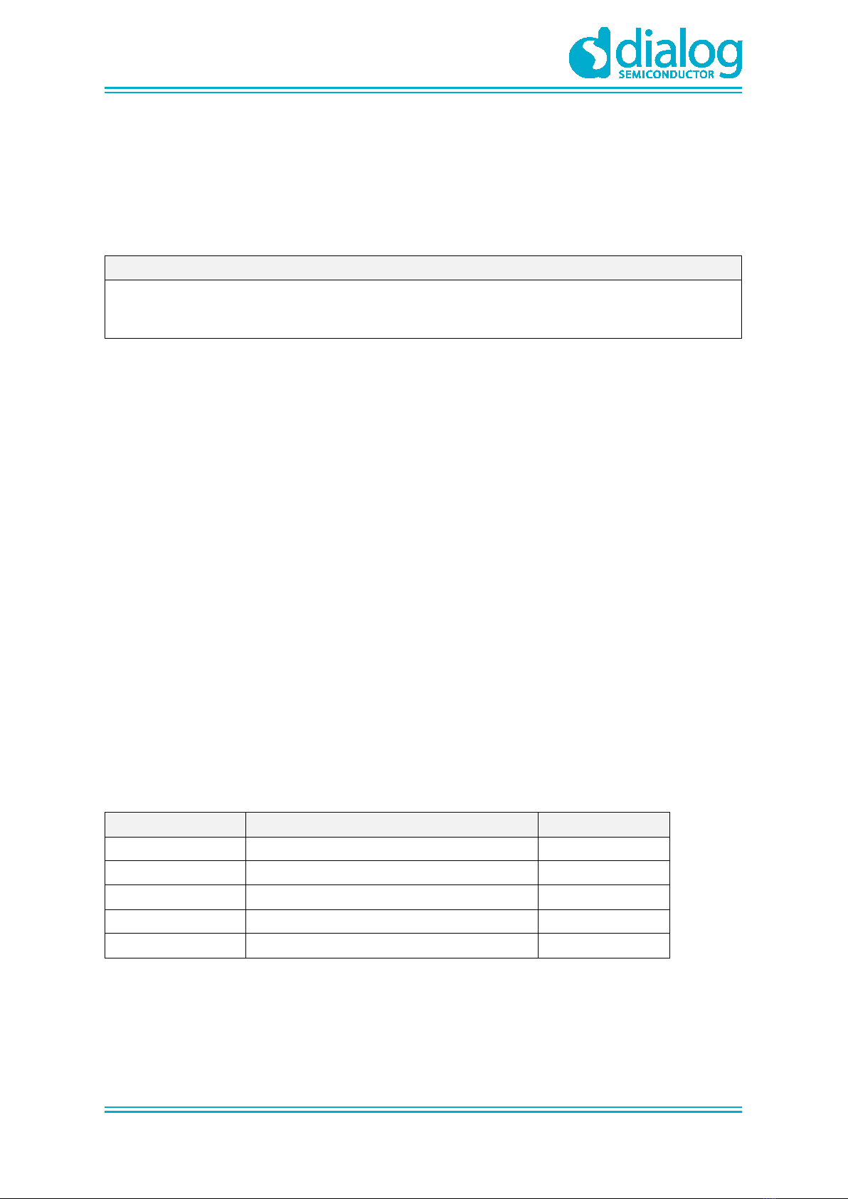
4.1 Description of the Switch....................................................................................................... 7
4.1.1 SW7 Pins Setting................................................................................................... 7
4.1.2 SW3 Pins Setting................................................................................................... 8
4.1.3 SW4 Pins Setting................................................................................................... 8
4.1.4 SW5 Pins Setting................................................................................................... 8
5 Wi-Fi Provisioning Setup.............................................................................................................. 9
5.1 DA16600 Connecting the Board ........................................................................................... 9
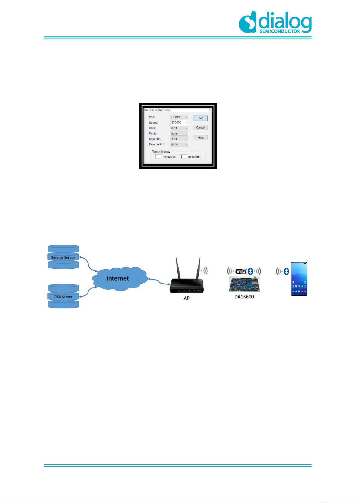
5.2 Configure the Serial Port for UART....................................................................................... 9
5.3 Setup for Wi-Fi Provisioning Using Bluetooth® LE .............................................................. 10
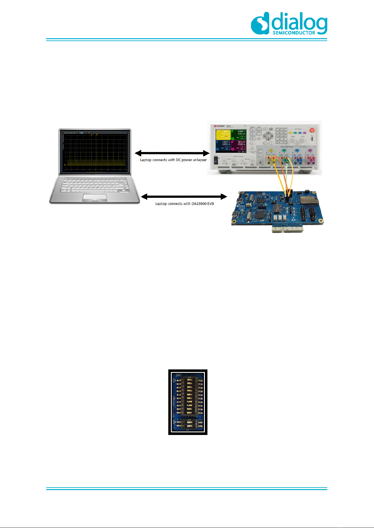
6 Current Measurement ................................................................................................................. 12
7 Hardware Setup for RF Test....................................................................................................... 12
7.1 Wi-Fi Test Setup ................................................................................................................. 12
7.2 Bluetooth® LE Test Setup.................................................................................................... 13
8 Firmware Update ......................................................................................................................... 14
8.1 Flash MAP........................................................................................................................... 14
8.2 Bootloader Image................................................................................................................ 15
8.3 Main RTOS Image .............................................................................................................. 15
8.4 DA14531 Image .................................................................................................................. 16
8.5 Download Image with Script (Macro) .................................................................................. 18
8.6 Serial Flash Recovery......................................................................................................... 20
8.7 Serial Flash Recovery from Boot ........................................................................................ 21
8.8 Boot Index Change ............................................................................................................. 23
8.9 MAC Address Checking...................................................................................................... 23
Revision History ................................................................................................................................ 24
Figures
Figure 1: Hardware Configuration ......................................................................................................... 6
Figure 2: JTAG Pin Connection............................................................................................................. 6
Figure 3: The SW7 Pins ........................................................................................................................ 7
Figure 4: The SW3 Pins ........................................................................................................................ 8
Figure 5: The SW4 Pins ........................................................................................................................ 8
Figure 6: The SW5 Pins ........................................................................................................................ 8
Figure 7: Check COM Ports on Device Manager.................................................................................. 9
Figure 8: Serial Port Setup .................................................................................................................. 10

UM-WI-051
DA16600 FreeRTOS Getting Started with EVK
User Manual
Revision 1.0
17-May-2021
CFR0012
3 of 25
© 2021 Dialog Semiconductor
Figure 9: Provisioning via Bluetooth® LE ............................................................................................. 10
Figure 10: Current Test Environment .................................................................................................. 12
Figure 11: SW3 and SW7 Set to Use AT-GUI..................................................................................... 12
Figure 12: SW3 and SW7 Set to Use SmartSnippets ......................................................................... 13
Figure 13: SW4 Set to Use Bluetooth® LE RF Path ............................................................................ 13
Figure 14: Mask ROM ......................................................................................................................... 15
Figure 15: Bootloader Prompt on Command Window......................................................................... 15
Figure 16: Load Image File.................................................................................................................. 15
Figure 17: Main Image Prompt on Command Window ....................................................................... 16
Figure 18: Load Image File.................................................................................................................. 16
Figure 19: DA14531 Image Prompt on Command Window................................................................ 16
Figure 20: Load Image File.................................................................................................................. 17
Figure 21: Factory Mode Prompt on Command Window.................................................................... 17
Figure 22. Load Macro ........................................................................................................................ 18
Figure 23. Download Bootloader......................................................................................................... 18
Figure 24. Download RTOS Image ..................................................................................................... 19
Figure 25: Download DA14531 Image ................................................................................................ 19
Figure 26: Initialize NVRAM ................................................................................................................ 21
Figure 27: Recovery Point in the EVK................................................................................................. 21
Figure 28: Run with BOOT Mode ........................................................................................................ 22
Tables
Table 1: Steps for Provisioning via Bluetooth® LE............................................................................... 11
Table 2: 4 MB Serial Flash Memory Map ............................................................................................ 14

UM-WI-051
DA16600 FreeRTOS Getting Started with EVK
User Manual
Revision 1.0
17-May-2021
CFR0012
4 of 25
© 2021 Dialog Semiconductor
1 Terms and Definitions
DPM Dynamic Power Management
AP Access Point
USB Universal Serial Bus
UART Universal Asynchronous Receiver-Transmitter
RTC Real Time Clock
WPS Wi-Fi Protected Setup
SSID Service Set Identifier
SDK Software Development Kit
ARP Address Resolution Protocol
2 References
[1] DA16200, Datasheet, Dialog Semiconductor
[2] UM-WI-049 DA16200 FreeRTOS SDK Startup Guide for Linux, User Manual, Dialog
Semiconductor
[3] UM-WI-050 DA16200 FreeRTOS SDK Startup Guide for Windows, User Manual, Dialog
Semiconductor
[4] UM-WI-046, DA16200, FreeRTOS SDK Programmer Guide, User Manual, Dialog
Semiconductor
[5] UM-WI-047 DA16200 FreeRTOS EVK User Manual, Dialog Semiconductor
[6] UM-B-114, DA14531, Devkit Pro Hardware, User Manual, Dialog Semiconductor

UM-WI-051
DA16600 FreeRTOS Getting Started with EVK
User Manual
Revision 1.0
17-May-2021
CFR0012
5 of 25
© 2021 Dialog Semiconductor
3 Software Development Kit (SDK)
The DA16600 Software Development Kit (SDK) has the same structure and environment as the
DA16200 SDK. For more information, see the materials available on https://www.dialog-
semiconductor.com:
●UM-WI-049 DA16200 FreeRTOS SDK Startup Guide for Linux, User Manual, Dialog
Semiconductor
●UM-WI-050 DA16200 FreeRTOS SDK Startup Guide for Windows, User Manual, Dialog
Semiconductor
●UM-WI-046, DA16200, FreeRTOS SDK Programmer Guide, User Manual, Dialog Semiconductor

UM-WI-051
DA16600 FreeRTOS Getting Started with EVK
User Manual
Revision 1.0
17-May-2021
CFR0012
6 of 25
© 2021 Dialog Semiconductor
4 DA16600 Module EVK
Figure 1 shows the hardware configuration of the DA16600 Module Evaluation Kit (EVK).
Figure 1: Hardware Configuration
DA16600 EVB has the following components:
1. Main board: DA16600 module (DA16600MOD-AAC) is installed.
2. DA16600MOD-AAC Wi-Fi & Bluetooth® LE Combo Module.
3. USB Port: UART0 is for debug, UART1 is for test.
4. USB Port: to debug, connect directly to DA14531, but do not use this port for normal operation.
5. JTAG PIN: allows connecting to I-jet (a JTAG debugger from IAR). See Figure 2.
○Pin 7 is keyed with a white plug, so Pin 7 should be removed on EVK
Figure 2: JTAG Pin Connection
6. RTC Wake up2 key: a switch to wake up the board from Sleep Mode.
7. RTC Power key: a switch to turn On/Off the board.
8. Pin (P1): a jumper to measure current at Bluetooth® LE part. For normal operation, this pin
should be shorted.
○Pull out the Short Pin cap and connect the jumper wire to measuring equipment
9. Pin (P2): a jumper to measure current at Wi-Fi part. For normal operation, this pin should be
shorted.
○Pull out the Short Pin cap and connect the jumper wire to measuring equipment
10. Connector CN4: GPIO test purpose connector.
○To test GPIO in J2 and J14, connect to LED by this connector

UM-WI-051
DA16600 FreeRTOS Getting Started with EVK
User Manual
Revision 1.0
17-May-2021
CFR0012
7 of 25
© 2021 Dialog Semiconductor
11. Switch SW3: a switch to connect directly to DA14531 and use UART to check Bluetooth® LE
performance.
○This switch is set to Off in normal operation
12. Switch SW4: a switch to control RF switch in DA16600MOD at test mode.
13. Switch SW5: a switch to check current consumption using power meter kit.
14. Switch SW7: a multipurpose switch.
○This switch is set to Off in normal operation
15. Button S1: WPS button using GPIOA6.
○Set to ON at Pin1 of SW7 to use this switch
16. Button S2: factory reset button using GPIOA7.
○Set to ON at Pin2 of SW7 to use this switch
17. Button S3: reset button of DA14531 in test mode.
18. Connector J2: GPIO connector.
19. Connector J14: GPIO connector.
4.1 Description of the Switch
4.1.1 SW7 Pins Setting
Figure 3: The SW7 Pins
●Pin1: to use the WPS function with GPIOA_6, turn on this pin to connect S1
●Pin2: to use the Factory reset function with GPIOA_7, turn on this pin to connect S2
●Pin3,4: to debug DA14531 with Keil
●Pin5,6: to check a debug message of DA14531 in the example application
●Pin7,8: to use UART1 of DA16200 with GPIOA_4,5

UM-WI-051
DA16600 FreeRTOS Getting Started with EVK
User Manual
Revision 1.0
17-May-2021
CFR0012
8 of 25
© 2021 Dialog Semiconductor
4.1.2 SW3 Pins Setting
Figure 4: The SW3 Pins
●Pin1,2: to use UART1 of DA14531 with P0_5 (1-wire UART)
4.1.3 SW4 Pins Setting
Figure 5: The SW4 Pins
To manually control the internal RF switch of DA16600, use:
●Pin1: if the RF path is connected to DA14531( Bluetooth® LE)
●Pin2: if the RF path is connected to DA16200( Wi-Fi)
4.1.4 SW5 Pins Setting
Figure 6: The SW5 Pins
To measure the current consumption with power meter kit, use:
●Pin1: to measure the current consumption of DA16200 ( Wi-Fi) which includes the RF switch
●Pin2: to measure the current consumption of DA14531 ( Bluetooth® LE)

UM-WI-051
DA16600 FreeRTOS Getting Started with EVK
User Manual
Revision 1.0
17-May-2021
CFR0012
9 of 25
© 2021 Dialog Semiconductor
5 Wi-Fi Provisioning Setup
5.1 DA16600 Connecting the Board
This section describes the installation procedure for the drivers, the configuration of the serial port,
and the steps needed to verify the connection with the PC as well as solutions to problems that may
occur.
On the first connection to a host PC running Microsoft Windows, the system detects several devices
and automatically installs all necessary drivers. If the drivers are not automatically installed, you can
get them from the following URL: http://www.ftdichip.com/Drivers/CDM/CDM21224_Setup.zip.
The Windows driver creates two virtual COM ports. The first COM port (lower number, COM35 in this
example) provides a UART interface for debugging or firmware download between the PC and the
DA16600. See Figure 7.
Figure 7: Check COM Ports on Device Manager
5.2 Configure the Serial Port for UART
For a Windows Host, the Tera Term utility is used to fully validate the connection to the DA16600
EVK.
Tera Term is a free software terminal emulator (communication program) which supports multiple
communication including Serial port connections. Download Tera Term from https://ttssh2.osdn.jp.
Run the teraterm-x.yy.exe and follow the installation wizard.
To make sure that the communication between the DA16600 EVK and host PC is properly
established, you need to verify the UART connection between the two nodes. Do the following:
1. Connect the DA16600 EVK to the PC USB port via USB cable.
2. Verify that the host identifies two serial ports as shown in Figure 7 – the second is connected to
UART (see Section 5.1).
3. In the Windows Start menu, open Tera Term.
4. In the Tera Term: New connection dialog, do the following:
a. Select Serial.
b. Select the COM Port to use.
c. Click OK.

UM-WI-051
DA16600 FreeRTOS Getting Started with EVK
User Manual
Revision 1.0
17-May-2021
CFR0012
10 of 25
© 2021 Dialog Semiconductor
5. Select Setup > Serial Port and configure your UART port using the parameters as shown in
Figure 8.
6. Open the Lowest COM port number assigned to the DA16600 EVK.
Figure 7 shows which port number to select in Device Manager in Windows. Make sure that the
UART is configured as shown in Figure 8.
Figure 8: Serial Port Setup
5.3 Setup for Wi-Fi Provisioning Using Bluetooth® LE
DA16600 module may be used in a product like Wi-Fi door-lock where Wi-Fi is playing the main role,
and Bluetooth® LE assists with Wi-Fi Provisioning at the product's initial setup (Out-of-Box). A
Bluetooth® LE peer application (for example Android/IOS mobile application) interacts with users to
set up the DA16600 device – by giving Wi-Fi Provisioning information (for example, Wi-Fi Home
router's SSID, password, server info, and other).
Figure 9: Provisioning via Bluetooth® LE
To set up Wi-Fi provisioning:
1. Download Dialog WiFIProvisioning App at App Store and install it.
2. Check the prompt [/DA16600] #.
3. Run Provisioning App and follow the steps in Table 1.

UM-WI-051
DA16600 FreeRTOS Getting Started with EVK
User Manual
Revision 1.0
17-May-2021
CFR0012
11 of 25
© 2021 Dialog Semiconductor
Table 1: Steps for Provisioning via Bluetooth® LE
1. Start App and select
the Start DA16600-
based button to
scan Bluetooth® LE.
2. Press the Start
button to start
provisioning.
3. Select DA16600-
BLE connect
Bluetooth® LE of
DA16600.
4. Press the Start
Wi- Fi network
scan button.
5. Choose an
application to
connect
6. Enter the password
for the selected
application.
7. Press the Connect
to…button.
8. Wi-Fi provisioning is
completed.

UM-WI-051
DA16600 FreeRTOS Getting Started with EVK
User Manual
Revision 1.0
17-May-2021
CFR0012
12 of 25
© 2021 Dialog Semiconductor
6 Current Measurement
For detailed information on Sleep mode, see the Low Power Operation Mode section in DA16200
Datasheet [1]. To measure current waveform, connect the EVK's current measurement point (P1 and
P2) with the measurement instrument (KEYSIGHT 14585A).
Figure 10 shows a typical test setup environment.
Figure 10: Current Test Environment
For more details on using power meter kit, see DA16600_SB_Power_Meter_Kit_User_Manual [1].
7 Hardware Setup for RF Test
DA16600MOD consists of DA16200 and DA14531 chipsets, see chipset GUI guides for details:
●UM-WI-004 DA16200 AT GUI Tool User Manual
●AN-B-077 DA14531 Bluetooth Direct Test Mode v1.0
7.1 Wi-Fi Test Setup
GPIOA4 and GPIOA5 can be used with UART to test RF performance of DA16200.
Turn on Pin7 and 8 of SW7 to use UART with GPIOA4 and GPIOA5.
Figure 11: SW3 and SW7 Set to Use AT-GUI

UM-WI-051
DA16600 FreeRTOS Getting Started with EVK
User Manual
Revision 1.0
17-May-2021
CFR0012
13 of 25
© 2021 Dialog Semiconductor
7.2 Bluetooth® LE Test Setup
P0_5 can be used with 1-wire UART to test RF performance of DA14531.
Turn on Pin1 and 2 of SW3 to use UART and turn off Pin7 and 8 of SW7.
Figure 12: SW3 and SW7 Set to Use SmartSnippets
SW4 can control RF switch. Turn on Pin1 of SW4 to control RF switch to Bluetooth® LE RF path.
Figure 13: SW4 Set to Use Bluetooth® LE RF Path

UM-WI-051
DA16600 FreeRTOS Getting Started with EVK
User Manual
Revision 1.0
17-May-2021
CFR0012
14 of 25
© 2021 Dialog Semiconductor
8 Firmware Update
The security features of DA16600 support Secure Boot to avoid booting with fake or untrusted
images and to protect against hacking. The DA16200 SoC includes a security hardware block called
CryptoCell-312 (CC312). With proper security keys and certificates installed (in OTP and images),
the DA16200 can boot in secure mode.
DA16600 requires three images. With a serial terminal tool, each image can be loaded individually
into the flash:
●<Bootloader image>: also known as Second Bootloader
○DA16600_[image_type]-[vendor]-[major]-[minior]-
[customer_ver]_[sflash_model].img
– [Image_type]: Bootloader (FBOOT), Main (FRTOS), or DA14531 image
– [vendor]: Internal use by vendor
– [major]: Major version
– [minor]: Minor version or SDK patch version
– [customer_ver]: User-configurable customer version
– [sflash_model]: sflash model or type used
○For example: DA16600_FBOOT-GEN01-01-xxxxx-xxxxxx_AT25SL321.img
●<Main image>: includes RTOS and applications
○For example: DA16600_FRTOS-GEN01-01-xxxxx-xxxxxx.img
●<DA14531 image>:
○For example: DA14531_multi_part_proxr.img
8.1 Flash MAP
DA16200 provides two image sets: #0 and #1. It is possible to use these regions for each image set
and change the index of the booting image set. The default value of the Boot Index points to #0.
Table 2: 4 MB Serial Flash Memory Map
Address Item Size
0x0000_0000 2nd Bootloader 139 kB
0x0002_2000 Boot Index 4 kB
0x0002_3000 RTOS #0 1600 kB
0x001E_2000 RTOS #1 1600 kB
0x003A_D000 DA14531 image + User Area #01 330 kB
NOTE
Secure Boot operation of the DA16600 FreeRTOS is supported in the DA16600 FreeRTOS SDK Official
Release version.
This feature is not available in the current Alpha Draft SDK package.

UM-WI-051
DA16600 FreeRTOS Getting Started with EVK
User Manual
Revision 1.0
17-May-2021
CFR0012
15 of 25
© 2021 Dialog Semiconductor
8.2 Bootloader Image
<Bootloader image> is also known as the second bootloader and is the first thing loaded into
memory for a factory-created DUT (for example with an empty flash).
Know that this image has SFDP information, which is important sflash type information, so always
load this image before loading the other images.
If you get a new SDK, then you always load the <Bootloader image> first.
1. Power on the DA16600 board.
2. At the [/DA16600] prompt, type reset to go to the Mask ROM prompt [MROM]. See Figure 14.
Figure 14: Mask ROM
3. At the [MROM] prompt, type loady boot. See Figure 15.
Figure 15: Bootloader Prompt on Command Window
4. Go to File > Transfer > YMODEM > Send to select the image file for the Bootloader. See
Figure 16.
○For example: DA16600_FBOOT-GEN01-01-xxxxx-xxxxxx_AT25SL321.img
○The result is printed at the end of the transfer. Ignore any messages like “err:..”
Figure 16: Load Image File
8.3 Main RTOS Image
This <Main image> contains RTOS, Wi-Fi libraries, and system/user applications.

UM-WI-051
DA16600 FreeRTOS Getting Started with EVK
User Manual
Revision 1.0
17-May-2021
CFR0012
16 of 25
© 2021 Dialog Semiconductor
1. At the [MROM] prompt, type loady 23000. See Figure 17.
NOTE
The RTOS address map register depends on the flash memory size. Therefore, the address must be 0x23000
for boot index 0 or 0x1E2000 for boot index 1. In this case, at the [MROM] prompt, type loady 23000 or
loady 1e2000.
For more details, see DA16200 SDK Programmer Guide [4].
Figure 17: Main Image Prompt on Command Window
2. Go to File > Transfer > YMODEM > Send to select the <Main image> file.
See Figure 18.
○For example: DA16600_FRTOS_GEN01-XX-YYYY-ZZZZZZ.img
Figure 18: Load Image File
8.4 DA14531 Image
This <DA14531 image> is downloaded to DA14531 during booting sequence.
1. At the [MROM] prompt, type loady 3ad000 1000 bin. See Figure 19.
Figure 19: DA14531 Image Prompt on Command Window
2. Go to File > Transfer > YMODEM > Send to select the <Main image> file.
○For example: da14531_multi_part_proxr.img

UM-WI-051
DA16600 FreeRTOS Getting Started with EVK
User Manual
Revision 1.0
17-May-2021
CFR0012
17 of 25
© 2021 Dialog Semiconductor
Figure 20: Load Image File
3. If the three images are loaded, then at the[MROM] prompt, type boot to boot your images.
4. Run factory reset as shown in Figure 21.
Figure 21: Factory Mode Prompt on Command Window
NOTE
Now all three required images are loaded.

UM-WI-051
DA16600 FreeRTOS Getting Started with EVK
User Manual
Revision 1.0
17-May-2021
CFR0012
18 of 25
© 2021 Dialog Semiconductor
8.5 Download Image with Script (Macro)
It is possible to download all images automatically with the use of a script.
1. In the Control menu, select Macro.
2. In the MACRO: Open macro dialog window, select DA16600_download.ttl file. See Figure 22.
The file path depends on the user`s image storage space.
Figure 22. Load Macro
3. The download starts with the bootloader image. See Figure 23.
Figure 23. Download Bootloader

UM-WI-051
DA16600 FreeRTOS Getting Started with EVK
User Manual
Revision 1.0
17-May-2021
CFR0012
19 of 25
© 2021 Dialog Semiconductor
4. Download RTOS image. See Figure 24.
Figure 24. Download RTOS Image
5. Download DA14531 image. See Figure 25.
Figure 25: Download DA14531 Image
6. DA16600 boots automatically after all images are downloaded.

UM-WI-051
DA16600 FreeRTOS Getting Started with EVK
User Manual
Revision 1.0
17-May-2021
CFR0012
20 of 25
© 2021 Dialog Semiconductor
NOTE
TTL command references:
send : Sends data.
Format : send <data1> <data2>....
sendln : Sends data with new-line.
Format : sendln <data1> <data2>....
waitln : Waits a line that contains string.
Format : waitln <string1> [<string2> ...]
mpause : Pauses.
Format : mpause <time>, milliseconds
getdir : Gets the current working directory for MACRO.
Format : getdir <strvar>
strconcat : Appends a string.
Format : strconcat <strvar> <string>
ymodemsend : Sends a file from the host with the YMODEM protocol.
Format : ymodemsend <filename>
8.6 Serial Flash Recovery
When the serial flash is replaced, the flash memory map is changed, or if you think that the flash
memory is corrupted, then follow the steps to re-initialize or recover sflash and check the process:
1. Boot DA16600.
2. At the [/DA16600] # prompt, run reset command.
3. At [MROM] prompt, run sflash info command to read serial flash information.
For example, SFLASH: 1f421615.
This is the flash product ID of AT25SL321. See also the IDs below.
AT25SL321 : 1f421615
4. Run ymodem sfdp command.
5. In the build\SBOOT\SFDP folder, find Flash SFDP file that corresponds to Flash ID as
AT25SL321.bin.
6. Run sflash erase 0 400000 command [MROM] to erase the entire flash for recovery.
Know that this command can take a long time to complete. Wait until the [MROM] prompt appears
again.
7. Re-load all images in the specified order for serial flash recovery.
a. [MROM] loady boot.
b. [MROM] loady 23000.
c. [MROM] loady 3ad000.
8. Run command boot to boot DA16600.
The image version is printed.
9. Initialize NVRAM for Serial Flash Recovery with following commands:
[/DA16600] # nvram
[/DA16600/NVRAM] # nvedit erase sflash
[/DA16600/NVRAM] # nvedit clear
[/DA16600/NVRAM] # nvcfg update sflash
Table of contents
Other Dialog Semiconductor Motherboard manuals

Dialog Semiconductor
Dialog Semiconductor GreenPAK Advanced UM-GP-002 User manual

Dialog Semiconductor
Dialog Semiconductor DA1468 series User manual

Dialog Semiconductor
Dialog Semiconductor DA852 Series User manual

Dialog Semiconductor
Dialog Semiconductor DA1468 series Installation and operating instructions

Dialog Semiconductor
Dialog Semiconductor DA7212 User manual

Dialog Semiconductor
Dialog Semiconductor DA9155M User manual

Dialog Semiconductor
Dialog Semiconductor UM-GP-007 User manual

Dialog Semiconductor
Dialog Semiconductor SLG46824 Operating instructions