Dialog Semiconductor DA7212 User manual

User Guide DA7212_Rev1v2 CONFIDENTIAL Page 1 of 34
User Guide
DA7212 User Guide –Rev1.2
DA7212 Ultra Low Power Codec
and
Power Commander™ GUI Software
Introduction
The DA7212 Evaluation Board has been designed to allow measurement and
evaluation of the DA7212 device.
All Audio Codec functionalities are self-contained within the Evaluation Board
(EVB).
The EVB is supplied with a USB memory stick containing various documents
and a GUI to allow the user to control the DA7212.
The GUI is called Power Commander™. It uses a simple graphical interface,
allowing the DA7212 to be controlled via a USB port of a PC.
The EVB has a number of jumper links to enable the user to change the
system configuration and to allow him to make appropriate measurements,
although, in reality, few jumper links are required to be altered for standard
operations of the DA7212.
MIC1_P/
DMICCLK
ADC L ADC
DIGITAL
FILTERS
Wind Noise
Filtering,
Automatic
Level Control
(ALC)
DAC
DIGITAL
FILTERS
Digital Mixer,
Digital
Volume,
5 Band
Equaliser,
Noise Gate
DAC L
AUX_L
AUX_R
FM
Radio
SP_P
PLL
+INL_PGA
MIC2_P
+INR
_PGA ADC R
DAC R
+
+
GND_CP
BCLK
DATOUT
WCLK
DATIN
DIGITAL AUDIO
INTERFACE (DAI)
SP_N
Speaker
Charge
Pump
HPCSP
HPCSN
1uF
1uF
VDIG
VMID
GND_A
Headphones
HP L
HP R
HP_L
HP_R
CONTROL
INTERFACE
SDA
SCLK
1µF
HPCFN
HPCFP 1uF
DACREF
BIAS
MIC1
_PGA
MIC2
_PGA
MIC1_N/
DMICIN
MICBIAS1
MICBIAS2
MIC2_N
MCLK
GND_SENSE
VDD_SP
VREF
MIC
BIAS1
MIC
BIAS2
1µF
AUXL
_PGA
AUX2
_PGA
DA7212
VDD_CP
VDD_MIC
BEEP
GENERATOR
+
VDD_IO
VDD_A
LDO
Figure :1 DA7212 Block Diagram

User Guide DA7212_Rev1v2 CONFIDENTIAL Page 2 of 34
User Guide
DA7212 User Guide –Rev1.2
Table of Contents
SUMMARY 3
HARDWARE 4
Power Supplies 6
Audio Connections 7
Jumpers Link Positions and Button Settings 8
CONTROL SOFTWARE 11
Installation 11
Control Panel 13
Status and Controls 14
Control Interface 17
Codec Config Page 18
DAI and PLL Page 19
Analogue Inputs 20
Analogue Outputs 21
Mixers 22
ADC Control 23
DAC Control 24
ALC Control 25
Tone Gen 26
Codec Registers 27
TROUBLESHOOTING 28
Software Issues 28
Hardware Issues 28
APPENDIX A –REGISTER TEXT FILE 30
APPENDIX A –SOCKETED MINIBOARD (169-01-A) 33
REVISION HISTORY 34

User Guide DA7212_Rev1v2 CONFIDENTIAL Page 3 of 34
User Guide
DA7212 User Guide –Rev1.2
Summary
This document provides some useful information to the user about the EVB
and the GUI to allow testing and evaluation of the DA7212 Ultra Low Power
Codec.
The hardware solution is based upon two PCBs:
- “EVALUATION MOTHERBOARD 170-03-A”
- “CUSTOMER REFERENCE BOARD 169-02-A”(DA7212 mini board)
The GUI, called Power Commander™, requires a PC operating Windows
2000/XP/Vista/Windows 7 with a USB1.1 or USB2 interface.
To run Power Commander™ under Windows Vista, set the default installation
location to „C:\Dialog Semiconductor\‟.
Note that Dialog recommends connecting the EVB to a 500 mA capable USB
port as we cannot guarantee that a USB hub (set to 100 mA) is sufficient to
operate it correctly.
See the section on Power Supplies below.
The GUI allows the user to: (i) configure the DA7212 using one of the several
pre-loaded initialisation files (i.e. start-up sequences) available; (ii) write and
read operations to all control registers; and (iii) monitor of device status.

User Guide DA7212_Rev1v2 CONFIDENTIAL Page 4 of 34
User Guide
DA7212 User Guide –Rev1.2
Hardware
The DA7212 Evaluation Board consists of two boards:
A daughterboard containing the DA7212, and the essential external
components. This board could also be used in standalone or as a module for
a customer development platform.
Figure 2: DA7212 Mini Board
Note a socketed mini board (169-01-A) is also available. See appendix B for
more information.
A motherboard containing many circuit blocks that allows for flexible
configuration and provides test access to the DA7212. It includes:
a. USB Interface with Control Interface level shifters
b. 1x audio optical input/output interfaces (with selection matrix)
c. USB reset and 3.3V reset switches
d. headphone output
e. line out outputs
f. auxiliary inputs
g. analogue/digital microphone inputs
h. master clock input
i. power supply inputs (VBAT, GND)

User Guide DA7212_Rev1v2 CONFIDENTIAL Page 5 of 34
User Guide
DA7212 User Guide –Rev1.2
A USB-I2C bridge is used for communication with the device, and there are a
number of external active components to reduce the requirement for external
circuitry.
Figure 3: Mother Board –Default Jumper positions shown in Red (power) and Blue (signal)
Note: The EVB has been configured by default to work from the mother
board‟s on-board regulators.

User Guide DA7212_Rev1v2 CONFIDENTIAL Page 6 of 34
User Guide
DA7212 User Guide –Rev1.2
Power Supplies
The DA7212 EVB is powered when a USB cable is connected to J1
(+5V_USB). With default jumper settings (J6, J7, J11, J14 and J19, J21), the
DA7212 device on the daughterboard is powered form the on-board
regulators.
As DA7212 supports a wide supply range the jumper configuration allows the
user to select one of two on-board supplies for each supply by connecting the
jumper link between pins 1&2 or 2&3 of the jumper. For maximum flexibility
the jumper link can be removed and a voltage can be supplied directly onto
pin 2 of the jumper with a ground connection connected to the A pin of the
jumper. Current measurements on individual supplies can also be performed
by connecting an ammeter between the supply and pin2 of the jumper.
Note: As VDD_IO supplies the IO voltage for the USB interface and level
translators jumper J10 has been provided for current measurements on this
supply of the DA7212 device. For current measurements on VDD_IO remove
the jumper link and insert an ammeter between pins 1 & 2 of J10.
Note: VDD_CP and VDD_DIG are not used in DA7212 and the jumper link
should be left unpopulated.

User Guide DA7212_Rev1v2 CONFIDENTIAL Page 7 of 34
User Guide
DA7212 User Guide –Rev1.2
Audio Connections
Connector
Name
Function
J17
AUX
Stereo single-ended auxiliary input
J30
MIC1_SE
Stereo single-ended microphone input
(connects to MIC1_P and MIC2_P)
J22
MIC2_SE
Stereo single-ended microphone input
(connects to MIC1_N and MIC2_N)
J26
Mono differential microphone input
Pin 1: MIC1_P
Pin 2: MIC1_N
Pin 3: GND
J27
Mono differential microphone input
Pin 1: MIC2_P
Pin 2: MIC2_N
Pin 3: GND
U7
S/PDIF IN
Digital optical input
U14
S/PDIF OUT
Digital optical output
J18
HP
Stereo single-ended headphone output
J24
LINEOUT
Differential line output (AC coupled,
use J25 for speaker)
J23
Differential line output (AC coupled,
use J25 for speaker)
Pin 1: LINE_P
Pin 2: GND
Pin 3: LINE_N
J25
Differential speaker output (DC
coupled)
Pin 1: SP_P
Pin 2: SP_N
J32
LINEOUT2
Unused
J31
Unused
Table 1 170-04-A Audio Connectors
User Guide DA7212_Rev1v2 CONFIDENTIAL Page 8 of 34
User Guide
DA7212 User Guide –Rev1.2
Jumpers Link Positions and Button Settings
Jumper number
Position
Function
J3 &J4
External VBAT and GND
connection
J5
1-2, (default)
VBAT select: VBAT is
generated from an on-board
regulator supplied from the
USB
2-3
VBAT select: VBAT is
supplied from J3&J4
J6
1-2, (default)
Connects VDD_A from
onboard 1.8V supply
2-3
Connects VDD_A from
onboard 2.5V supply
A
GND connection for
connecting external supply
between pin 2 and A
J7
1-2, (default)
Connects VDD_IO from
onboard 1.8V supply
2-3
Connects VDD_IO from
onboard 3.3V supply
A
GND connection for
connecting external supply
between pin 2 and A
J8
On, (default)
Connects USB I2C SCLK to
device
J9
On, (default)
Connects USB I2C SDATA to
device
J10
On, (default)
Connects VDD_IO to the
DA7212 device.
J11
1-2
Connects VDD_SP from
onboard 3.3V supply
2-3, (default)
Connects VDD_SP from
VBAT
A
GND connection for
connecting external supply
between pin 2 and A
J12
1-2
MCLK comes from the SPDIF
interface
3-4, (default)
MCLK comes from the USB
interface
5
GND pin
6
External MCLK pin,
anexternal MCLK can be
connected between pins 5
User Guide DA7212_Rev1v2 CONFIDENTIAL Page 9 of 34
User Guide
DA7212 User Guide –Rev1.2
and 6.
J13
1-2
Inserts a 16ohm load across
the left headphone output
for test purposes
2-3
Inserts a 32ohm load across
the left headphone output
for test purposes
J14
1-2
Connects VDD_MIC from
onboard 3.3V supply
2-3, (default)
Connects VDD_MIC from
onboard 2.5V supply
A
GND connection for
connecting external supply
between pin 2 and A
J15
Allows connection of an
external MCLK using an SMB
connector. J12 should have
it’s jumper link removed
when using this option.
J16
1-2, (default)
Connects the SPDIF/USB
BCLK to the DA7212 device
3
GND for connecting BCLK
to/from an external source
between 2-3 (for example
Audio Precision PSIA cable)
4-5, (default)
Connects the SPDIF/USB
WCLK to the DA7212 device
6
GND for connecting WCLK
to/from an external source
between 5-6 (for example
Audio Precision PSIA cable)
7-8, (default)
Connects the SPDIF/USB
DIN to the DA7212 device
9
GND for connecting DIN
from an external source
between 8-9 (for example
Audio Precision PSIA cable)
10-11, (default)
Connects the SPDIF/USB
WCLK to the DA7212 device
12
GND for connecting DOUT to
an external source between
11-12 (for example Audio
Precision PSIA cable)
J19
1-2
Not Used
Do not connect for DA7212
2-3,
A
J20
1-2
Inserts a 16ohm load across

User Guide DA7212_Rev1v2 CONFIDENTIAL Page 10 of 34
User Guide
DA7212 User Guide –Rev1.2
the right headphone output
for test purposes
2-3
Inserts a 32ohm load across
the right headphone output
for test purposes
J21
1-2, (default)
Not Used
Do not connect for DA7212
2-3
A
S1
Regulator Reset button:
Resets the 3.3V, 2.5V, 1.8V
and 1.1V regulators
S2
USB Reset button:
Resets the USB sub system
Table 2: 170-04-A Jumpers Link Positions and Button Settings

User Guide DA7212_Rev1v2 CONFIDENTIAL Page 11 of 34
User Guide
DA7212 User Guide –Rev1.2
Control Software
Installation
From the USB memory stick provided with the EVB box, run the „setup.exe‟
file (DA7212_USB\DA7212 GUI\setup.exe).
Click “Next>>”.
Click “Next>>”.
User Guide DA7212_Rev1v2 CONFIDENTIAL Page 12 of 34
User Guide
DA7212 User Guide –Rev1.2
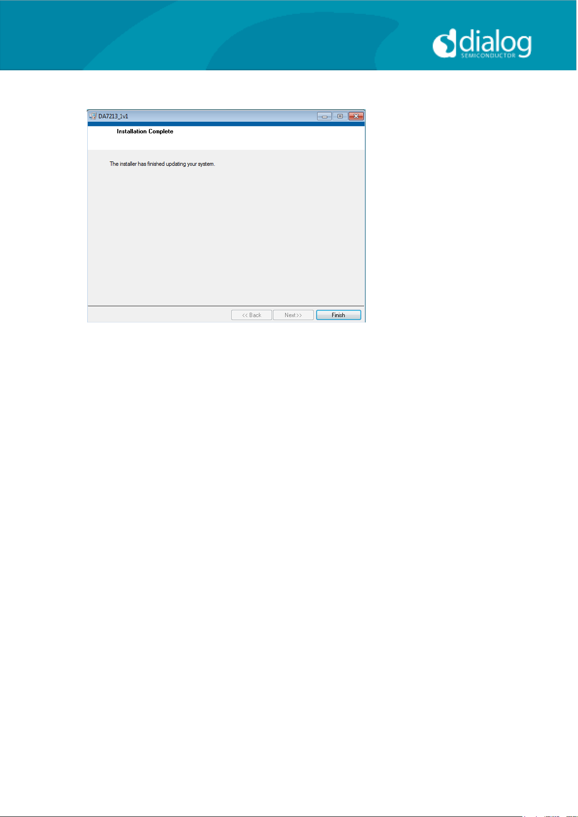
Click “Finish”.
You may need to restart your computer; in this case a pop up window will
appear asking you to do so.
Once your computer has restarted, plug the USB cable to the EVB and
Windows should detect the USB device and automatically install the driver. If
not, the driver is located on this DA7212 USB stick
User Guide DA7212_Rev1v2 CONFIDENTIAL Page 13 of 34
User Guide
DA7212 User Guide –Rev1.2
Control Panel
Run the DA7212 program by clicking the shortcut on the appropriate item in
the Start menu. The best setting for the PC display size is 1024x768 pixels or
above. Font size on the PC display should be Normal (95dpi). It is important to
note that a display size other than the recommended setting may affect the
way in which the panels appear.
The following screen appears, with the “USB OK?” LED lit if the USB interface
is correctly connected and operational.
To start the device, plug in the USB cable.
Figure 4 Initial Interface
If the Reset LED is blinking yellow, it indicates that the device is not yet
communicating via the I2C interface. See Troubleshooting for more details.
User Guide DA7212_Rev1v2 CONFIDENTIAL Page 14 of 34
User Guide
DA7212 User Guide –Rev1.2
Status and Controls
Polling Enabled BY default the current page contents is updated via
polling the I2C interface. If disabled, these readbacks
are suppressed. This is used to force the
communication over the bus to be silent.
If this is set to automatic, the program will only poll the
device while the application is the topmost window. If
obscured by another program or window, polling will
be disabled.
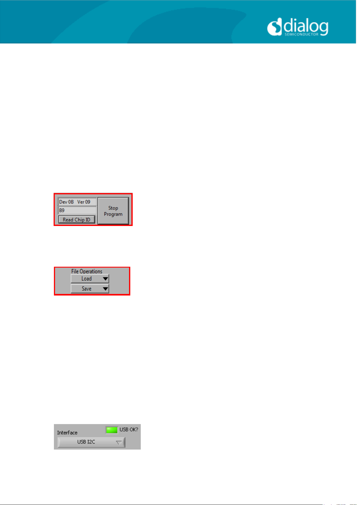
LED If the device is active this LED is green, or red if
inactive.
This indicates the device version when the device
is active. When inactive, version status will not be
correct.
Stop Program This terminates the program. If there are unsaved
changes, a dialog box is displayed.
Load Loads previously saved text files, send all
Registers and read back all registers.
“Load”opens a dialog box to select, view, copy or
re-name a file.
Load Codec file opens a dialog box to allow selection of a
codec setup file in the “\Codec Setups” directory.
Save Saves current panel state to a text file. Selecting
“Save Codec file..” saves the codec registers in a slightly
different format. Selecting “Register Dump” option saves
current register values to the text file. See Appendix A.
Note: Difference between “Save”and “Register Dump”is that the “Save”
dumps the contents of all panel controls to the file (a save state operation);
whereas, “Register Dump” reads the device contents (including status
registers) into the file. Note that some codec registers do not have readback
capability.
Interface Selects between USB I2C control
and offline mode. Switching to offline,
then back to USB reinitialises the
USB interface.

User Guide DA7212_Rev1v2 CONFIDENTIAL Page 15 of 34
User Guide
DA7212 User Guide –Rev1.2
USB OK? Indicates that the USB is OK and
communicating.
Slave Address
Sets slave address of device. This affects all
I2C communications.
The codec slave addresses for DA7212 is 0x34.
Note that this is the 8bit value (34h for Write,
35h for Read).
Send Sends a single byte data to I2C device
using Slave Address, Register Address and
Data to Send.
Read Reads single byte data from I2C device
using Slave Address and Register Address.
Find Finds a control matching a full or partial
register name, a control bit name, a register
number (e.g. R23 or 17h). Pressing “Find”
repetitively will step through all matching
items.
Note: If Device Address does not match the port numbers on the device, this
can be used to control/read any other device on the I2C bus.

User Guide DA7212_Rev1v2 CONFIDENTIAL Page 16 of 34
User Guide
DA7212 User Guide –Rev1.2
Synchronise Panel from Device
Reads all the register contents of the device
and updates the panel to match.
Synchronise Device from Panel
Writes all the device registers to match the
panel. (Refresh operation)
Reload Configuration
Resets registers to values specified in
configuration file for the PMIC section and default
values for the codec.
Clear all I2C readback indicators Sets all readback indicators to 0.
Read All Registers Reads all registers, comparing with
the panel controls.

User Guide DA7212_Rev1v2 CONFIDENTIAL Page 17 of 34
User Guide
DA7212 User Guide –Rev1.2
Control Interface
The Codec Config, DAI and PLL, Analogue Inputs, Analogue Outputs, Mixers,
DAC Control, ADC Control, ALC control and Tone Gen pages all have the
same format.
Each register cluster comprises a control with a mixture of Boolean toggle
buttons, multi-value ring controls, or slide controls, as well as a hexadecimal
indicator showing the total equivalent register value and a readback indicator
showing the current register settings. The Event Register is labeled with a
Register number in decimal and its hexadecimal equivalent.
The Readback indicator readings can be switched individually to decimal,
octal, hexadecimal or binary by clicking on the “x”, or they may all be changed
at once between Hex and Binary by the “View>Binary Indicators” menu item.
User Guide DA7212_Rev1v2 CONFIDENTIAL Page 18 of 34
User Guide
DA7212 User Guide –Rev1.2
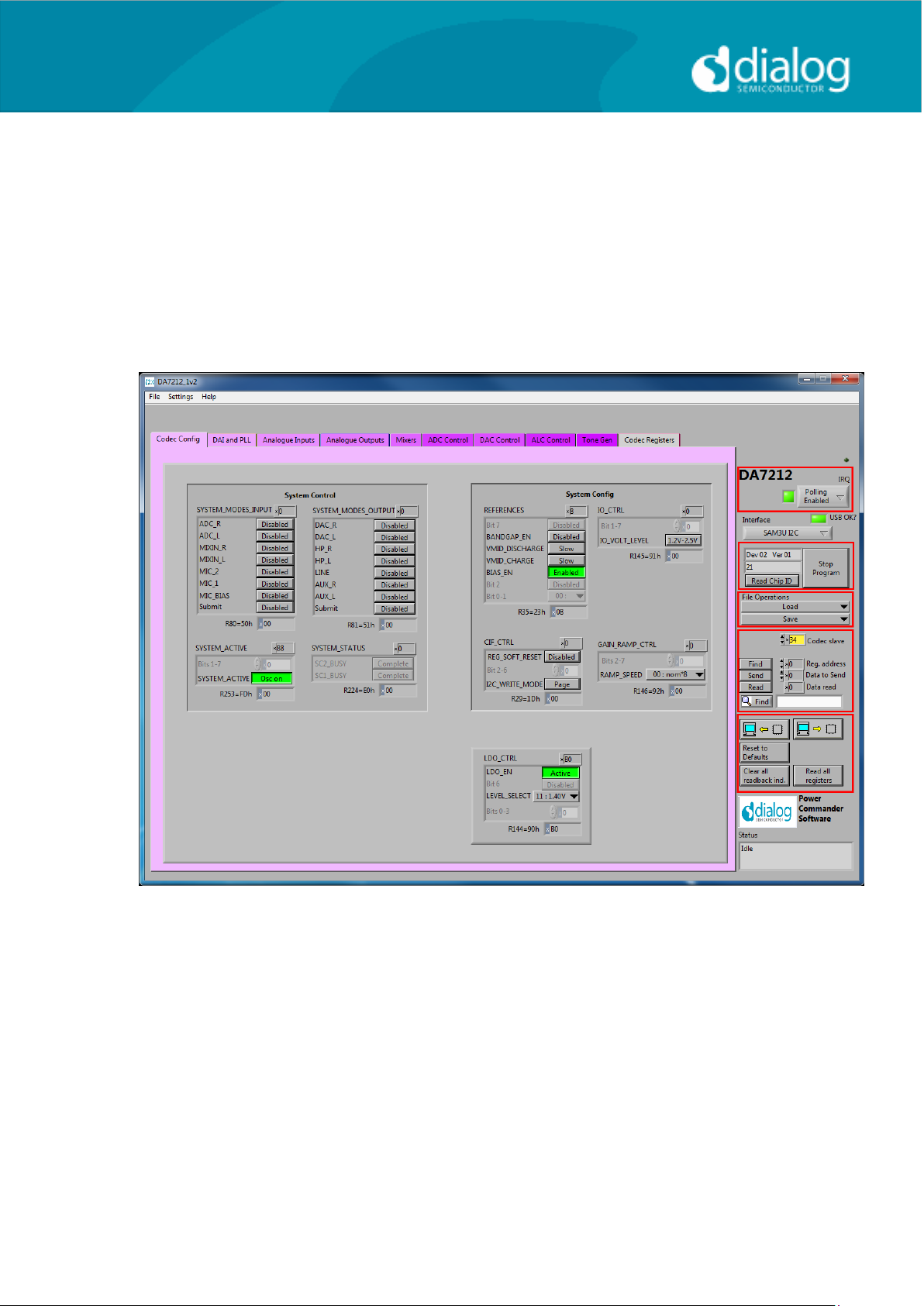
Codec Config Page
The Codec Config page allows access to the System Controller as well as
some basic system settings such as the references, IO levels and digital LDO.
To use the System Control panel (de)select the blocks as required for the
inputs and outputs and click the Submit button to apply the changes. If no
blocks are active then the System Active panel can be used to disable the on-
chip oscillator and put DA7212 into an ultra-low power standby state. The CIF
CTRL panel can be used to reset the chip and return all the registers to their
hardware defaults.

User Guide DA7212_Rev1v2 CONFIDENTIAL Page 19 of 34
User Guide
DA7212 User Guide –Rev1.2
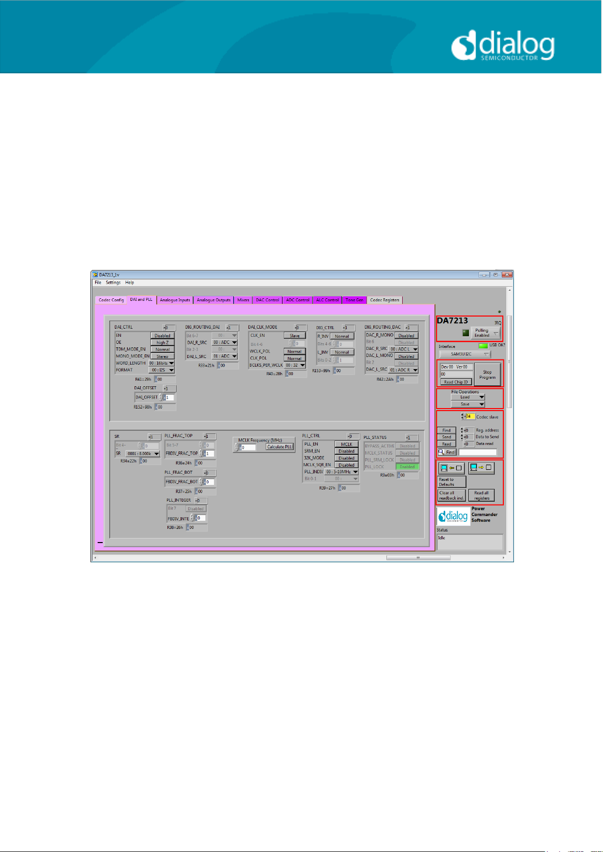
DAI and PLL Page
The DAI and PLL page allows control of the digital audio interface and phase-
locked loop. The DAI CTRL panel sets the format on the DAI and the DAI CLK
MODE panel sets the master/slave mode as well as the clock polarity and
number of BCLKS per WCLK. The DIG ROUTING DAI panel selects the data
source for the DAI and DIG ROUTING DAC selects the data source for the
DAC.
The PLL Control panel contains all the settings for the PLL and on-chip
clocking. The SR panel sets the sample rate being used. The PLL CTRL
panel sets the input clock rate, whether the PLL is enabled and whether
sample rate matching (SRM) is required to track the DAI in slave mode. If the
PLL is required, the three FBDIV panels control the value of the feedback
divider. The required values can be calculated using the DA7212 PLL
Calculator spreadsheet, or they can be determined automatically by entering
the supplied MCLK frequency and pressing the Calculate PLL button. The
current status of the PLL is shown in the PLL STATUS panel. The PC COUNT
panel controls the behavior of the internal program counter.
User Guide DA7212_Rev1v2 CONFIDENTIAL Page 20 of 34
User Guide
DA7212 User Guide –Rev1.2
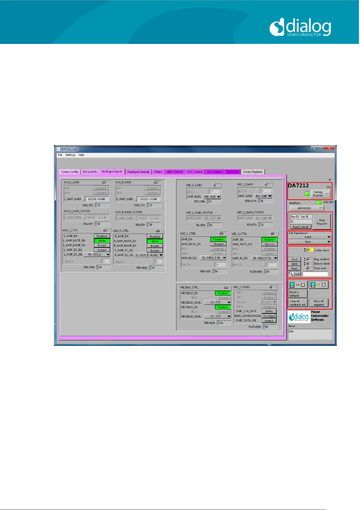
Analogue Inputs
The Analogue Inputs page controls the input amplifiers and microphone
biases. Each of the GAIN panels sets the target gain for the amplifiers, and
the GAIN STATUS shows the currently active gain setting. Each of the CTRL
panels sets the enable, mute, and gain change behavior (ramped or zero-
crossed) for the amplifiers. The MIC CTRL panels allow selection of single-
ended or differential input signal. The MICBIAS CTRL panel enables and sets
the output level for the microphone bias outputs. The MIC CONFIG panel sets
the clock and data format when digital microphones are used.
Table of contents
Other Dialog Semiconductor Motherboard manuals

Dialog Semiconductor
Dialog Semiconductor GreenPAK Advanced UM-GP-002 User manual

Dialog Semiconductor
Dialog Semiconductor DA1468 series User manual

Dialog Semiconductor
Dialog Semiconductor DA852 Series User manual

Dialog Semiconductor
Dialog Semiconductor DA9155M User manual

Dialog Semiconductor
Dialog Semiconductor SLG46824 Operating instructions

Dialog Semiconductor
Dialog Semiconductor DA16600 User manual

Dialog Semiconductor
Dialog Semiconductor UM-GP-007 User manual

Dialog Semiconductor
Dialog Semiconductor DA1468 series Installation and operating instructions


