Dialog Semiconductor DA852 Series User manual

Display Controllers
©Dialog Semiconductor2008. Allrights reserved.
All brand and product names aretrademarksor servicemarks of their respectiveowners. Printed in Europe. DA852x-UG02-608Page1of47
UserGuideRelease2.0
DA852XEInkEvaluationKit
1Summary
ThisdocumentdescribesthehardwareandsoftwareproducedbyDialogSemiconductortoallowuserstoevaluateEInk
segmenteddisplaysalongwiththeDA852Xfamilyof driverICsfromDialogSemiconductor.Thesystemisdesignedwith
thefollowingobjectives:
•Toassessthe suitabilityof the EInktechnologyforagiven productconcept,
•Toquicklyevaluatethe performanceof the display(forexample,intermsofitscontrast ratio,look
and feel,and transition speed),
•Todesign the display(particularlyitssize, segmentation, and otherparameters),
•Toevaluatedifferentdriving waveforms,and
•Tostartthe design ofthesoftwareforthe microcontrollerbeing used inthe system.
ThesoftwareusesaPCoperatingWindows2000/XPwithaUSB1.1orUSB2interface.Thesoftwarehasnotbeen
extensivelytestedon WindowsVista,but hasbeenshowntofunction.See Section 3.1.2
1.1ProductLineup
TheDA852XEInkEvaluationKitserieshasbeenproducedtoallowevaluationoftheDA852Xseriesdrivers
Thesecurrentlycomprise:
ProductLineup
DeviceP/N Description Package EvaluationKit
P/N
DA8521-00-BC-1 64 segments 80-pin5x5mm VTLGA DA8521-eval
DA8522-00-BD-1 96 segments 112-pin6x6mm VTLGA DA8522-eval
DA8523-00-BE-1 192 segments 208-pin12x7mm VTLGA DA8523-eval
DA8524-00-BF-1 256 segments 272-pin20x10mm VTLGA DA8524-eval
AllkitsincludeaCD ROMcontainingdocumentationanddriverfiles.Thedriversoftwareusesasimplegraphical
interface,allowing theDA852XseriesboardtobecontrolledviaaUSBportof aPC.Thesoftwareisthesameforall the
different kits.
1.2Feedback/ContactDetails
Wewelcomefeedback ofalltypesinordertomakethiskitandUserGuideaccelerateyourprojectdevelopment. Please
directanycomments,questions,support issuesorgeneralremarks,totheDisplayDriverApplicationsDepartmentat
Dialog Semiconductor,contactdetailsbelow:
Contact:DisplayDriverApplicationsDepartment
Company:DialogSemiconductor
Address: Windmill Hill,
WhitehillWay,
Swindon. SN56PJ.
UK
Telephone: +44 1793875327
Fax: +441793875328
E-mail: EPDsupport@diasemi.com

©Dialog Semiconductor2008. Allrights reserved.
All brand and product names aretrademarksor servicemarks of their respectiveowners. Printed in Europe. DA852x-UG02-608 Page2of47
UserGuideRelease2.0
DA852XEInkEvaluationKit
Display Controllers
1SUMMARY...........................................................................................................1
1.1 ProductLineup.....................................................................................................1
1.2 Feedback/ContactDetails....................................................................................1
2HARDWARE.........................................................................................................5
2.1 DA852XEvaluation Board....................................................................................5
2.1.1 USB Connector...................................................................................................5
2.1.2 PowerSupplies...................................................................................................5
2.1.3 Jumpers..............................................................................................................5
2.1.4 ExpansionInput..................................................................................................6
2.1.5 ExpansionOutput...............................................................................................6
2.1.6 FlexConnection..................................................................................................7
2.1.7 OutputConnectors..............................................................................................7
3SOFTWARE.........................................................................................................9
3.1.1 ReleaseNotes....................................................................................................9
3.1.2 Installation..........................................................................................................9
3.1.3 ControlPanel....................................................................................................11
3.1.4 InterfaceDescription.........................................................................................12
3.2 Common Controls..............................................................................................12
3.2.1 DeviceType......................................................................................................12
3.2.2 Top Plane Connection(s)..................................................................................12
3.2.3 FieldConnection(s)...........................................................................................12
3.2.4 StatusMessage................................................................................................12
3.2.5 USB OK?Indicator...........................................................................................12
3.3 DA852XPanel.....................................................................................................12
3.3.1 Direct Control....................................................................................................13
3.4 ParameterControlPanel....................................................................................13
3.4.1 Waveform Selection..........................................................................................15
3.4.2 FileMenu..........................................................................................................16
3.4.3 Toolbar.............................................................................................................17
3.4.4 Image Controls.................................................................................................18
3.4.5 Image Information.............................................................................................20
3.5 FileFormats........................................................................................................21
3.5.1 The ConfigurationFiles.....................................................................................21
3.5.2 The ImageFile..................................................................................................22
3.5.3 The Map File.....................................................................................................23
3.5.4 The SlideFile...................................................................................................24
3.5.5 Slide filenamesfornumbersand alphanumerics..............................................25

©Dialog Semiconductor2008. Allrights reserved.
All brand and product names aretrademarksor servicemarks of their respectiveowners. Printed in Europe. DA852X-UG02-608Page3of47
UserGuideRelease2.0
DA852XEInkEvaluation Kit
Display Controllers
3.5.6 NumberEntry...................................................................................................25
3.5.7 AlphanumericEntry..........................................................................................26
3.6 Programming Information..................................................................................28
3.6.1 Decode statestoprovide drivewaveform.........................................................29
3.6.2 CreatingaHexstringfromstateoutputs...........................................................30
3.6.3 Decode ahexstringtostatearray....................................................................30
4TUTORIAL–AMEMORYGAUGEEXAMPLE..................................................31
4.1 Connecting theDisplayHardware.....................................................................31
4.2 Creating aNewProject.......................................................................................33
4.3 Top PlaneConnection........................................................................................34
4.4 LoadImageofDisplay........................................................................................34
4.5 Mapping theSegments......................................................................................35
4.6 Creating theMapFile.........................................................................................36
4.7 Creating aSlideShow........................................................................................39
5WAVEFORMPHASE TABLE............................................................................40
6CASCADECONNECTION.................................................................................43
7FLEX CONNECTION..........................................................................................44
8TROUBLESHOOTING.......................................................................................45
8.1 Softwareissues..................................................................................................45
8.2 HardwareIssues.................................................................................................45
9RELEASE NOTES FORVERSION2.0..............................................................46

©Dialog Semiconductor2008. Allrights reserved.
All brand and product names aretrademarksor servicemarks of their respectiveowners. Printed in Europe. DA852x-UG02-608 Page4of47
UserGuideRelease2.0
DA852XEInkEvaluationKit
Display Controllers
Notices
Dialog Semiconductorprovidesthisevaluationkit(the“product”)forengineering evaluationpurposesonly. It isnot
consideredsuitableforuseinend products.
Thisproductcontainsstaticsensitivedevicesand careshouldbetakenthatitishandledappropriatelytoavoiddamage
fromelectrostaticdischarge.DialogSemiconductordoesnotassumeresponsibilityforthesafehandlingoftheproduct
afterithasbeendeliveredand subsequent disposal.
Asaprototypetheproducthasnotbeensubjecttoanyregulatoryapproval(CE,FCC,etc.)and maynotmeetthe
technicalrequirementsfromsuchbodiesforelectromagneticcompatibility.DialogSemiconductordoesassume
responsibilityforsuchcompliance.
Whilstcarehasbeentakeninthedesign oftheproduct, DialogSemiconductorassumesnoliabilityfromtheuserforany
indirect,incidentalorconsequentialdamagesresultingfromuseoftheproduct orfromapplicationsassistancegivenin
supportoftheproduct.
Dialog Semiconductorreservestherighttoalterwithoutnoticethespecification,design,priceorconditionofsaleofthis
product.
Beforeusingtheproductwerecommend thattheuserreadsboththeguideandtheproductdatasheet tofamiliarise
themselveswiththeoperationoftheproduct.
Maximumsupplyvoltagesforthisproductaredefinedwithinthisguide; operation outsidethesevoltagesmayresultin
permanent damagetotheproduct. Applyingloadsoutsidetherangespecifiedinthisguideortheproductdatasheetmay
alsoresultinpermanentdamage.It ispossiblethatduringoperationwithhighload currentsorvoltagesbeing applied,
somecomponentsmayoperateatanelevatedtemperature.Careshouldbeexercisedwhentouchingcomponentson
theboardinsuchcircumstances.

©Dialog Semiconductor2008. Allrights reserved.
All brand and product names aretrademarksor servicemarks of their respectiveowners. Printed in Europe. DA852X-UG02-608Page5of47
UserGuideRelease2.0
DA852XEInkEvaluation Kit
Display Controllers
2Hardware
2.1DA852XEvaluationBoard
TheDA852XEvaluationBoardcomprisestheDA852Xdevice, aUSBbridgeforPCcommunicationwiththedevice,and
afewexternalactivecomponentstoreducetherequirementforexternalequipment. ThedeviceU3isalevelshifter,
usedtomovethedigitalcontrolsignalsfromthe3.3vdomaintothechipsupplydomain.
Theboardcanbeusedflexiblywithexternalhardware, andcan accept connectionsfromanexternalmicrocontroller.
TheboardisdesignedtobecascadablewithotherDA852Xboards,toallowconnectionoflargedisplayswithmorethan
256 segments.
Figure1.DA8521 PCB layout
ThehardwaresolutionisbaseduponPCBsnumbered44-179-73-04/05/06/07-Aforthe64, 96,192and256segment
driverdevicesrespectively.
2.1.1USBConnector
TheUSB interfaceisusedtocontroltheboardfromthePC.TheUSB interfacemayalsobeusedtopowertheboard.
TheUSB interfaceconsumesapproximately50mainthestandbystate.
2.1.2PowerSupplies
Theboardisintendedtobesuppliedbyasingle1.8v-3.3vsupplyattachedtothetwo4mmbananasocketsmarked
VDD and GND.
It mayalsobepoweredwith3.3vdirectlyfromtheUSB interfacebysettingjumperJP1totheUSB position. Note:If JP1
issettotheExternalposition,VDD shouldbepoweredbefore, orassoonaspossibleaftertheUSB lead ispluggedin.
2.1.3Jumpers
JP1ThiswillconnectVDD tothe3.3vsupplygeneratedbytheUSBmodule.

©Dialog Semiconductor2008. Allrights reserved.
All brand and product names aretrademarksor servicemarks of their respectiveowners. Printed in Europe. DA852x-UG02-608 Page6of47
UserGuideRelease2.0
DA852XEInkEvaluationKit
Display Controllers
JP2RemovingthisdisablesthedigitalI/O signalsfromthelevelshiftertotheDA852X.Thisallowsdirectaccess and
controlofthechipfromanexternalcontrollerviatheexpansioninputpins
JP3Removalof thisdisablestheChipSelectsignaltotheDA852Xdevice. Thiswouldonlybedoneifusing the
externalFlexconnection.
JP5Removalof thisdisablestheStandbyBsignaltotheDA852Xdevice. Thiswouldbedoneif thedeviceisusing
an external15vsupply,orisbeingoperatedasaslavecascadeddevice.
JP4Selectsthe15voltsupplyeitherfromtheinternalchargepump, orfromtheEXT_V15pin.
Thenormalpositionsofthejumpersareasshownbelowinred:
Figure2.Normal PositionofJumpers
2.1.4ExpansionInput
Thisseriesoftestpointscan beusedto
•MonitorthecontrolsignalsfromtheUSB interface
•Transmitthesignalstoexternalhardware(e.g.theDA852XdevicemountedontoaflexiblePCB).
•AllowanexternalmicrocontrollertoprovidethecontrolsignalstotheDA852Xdevice.(RemoveJP2)
•AcceptthesignalsfromtheExpansion OutputportofanotherDA852Xboard.(RemoveJP2)
•Notethat CSN1isActiveHigh, labellingonthePCBisincorrect
2.1.5ExpansionOutput
Thisseriesoftestpointscan beusedto
•MonitorthecontrolsignalsfromtheUSB interface
•Send thecontrolsignalstotheExpansionInputportof anotherDA852Xboard.
•Notethat CSNisan ActiveHigh output, labellingonthePCBisincorrect.
NotethatthesignalsDATAOUTandCLKOUTaredifferentfromtheExpansion Inputport. Thesearepassedfromthe
DATAOUTand CLKOUTpinsoftheDA852Xdeviceand allowcascadeconnectionofdevices
The3V3_OUTpowersupplyisintendedtosupplytheUSB interfacecomponentsofthesecondboard,whichwillnotbe
pluggedintotheUSB port.

©Dialog Semiconductor2008. Allrights reserved.
All brand and product names aretrademarksor servicemarks of their respectiveowners. Printed in Europe. DA852X-UG02-608Page7of47
UserGuideRelease2.0
DA852XEInkEvaluation Kit
Display Controllers
2.1.6FlexConnection
TheconnectorsJ17 and J18 have16connectionsona0.5mm pitch. ThisisintendedtoconnectviaasuitableFPC
socket ordirectconnectiontoan assemblywhichcontainsboththedisplaysurfaceand thedriverdevicemountedon a
flexPCB.
2.1.7OutputConnectors
ThesegmentoutputsfromtheDA852Xdeviceareroutedtoaseriesofparallel-connectedinterfaces.NotethatALL
connectorsarenumberedfrom1upwards, whereassegment outputsarenumberedfrom0upwards.That isconnector
pin1isdrivenbyDA852XsignalDD0and connectorpin20isdrivenbyDA852XsignalDD19.
ItisanticipatedthattheEInkDisplayhasaflexibletailofatleast 4mm,withapitchdownto0.2mm.Somewillbe
intendedfordirect-to-boardbonding using ACFmaterial,otherswillbeintendedtoconnectviaaninlineorlowprofile
FPCsocket. Itisnot possibleforustopredict allthepossiblevariations,sowehaveallowedforthefollowing:
0.2mm pitchFPCconnectiondirect-to-board
0.4mm and0.5mm FPCconnectiondirect-to-boardorsocket(64,96 outputversionsonly).
0.3mm narrowpitchconnectorwithstaggeredpins. Thisgives0.6mm pitchonsolderpins
0.4mm and0.5mm narrowpitchconnectorwithin-linepins(64,96outputversionsonly).
1.27mmIDC socketsforconnectionviaribboncable.
Typically,inlineFPCsockets, fordirectinsertionoftheFPCtail,areavailableforup toabout70 ways.Lowprofile
sockets,usingcomplementarymating halveson PCBandflexibletail,areavailableforup toabout160ways.Typical
manufacturersareJAE,Panasonic,Hirose,Molexetc.
Theseconnectionsarepresent onbothsidesofthePCB, allowing fortop-sideandbottomsideconnections. However,if
thedisplayinusehastheconnectionsonthesamesideasthe visiblesurface,itshouldbeappreciatedthatpartofthe
displaymaybemaskedbythePCBiftheflexibletail isshort, asitisnotpossibleforall theconnectorpositionstobeat
theedgeofthePCB.
Forsuchadisplay,thereareseveralsolutions:
a)Connectthedisplaytothetop sideconnectorsandbend thedisplaytomakethedisplaysurfacevisible. The
usershouldtakecaretoavoidcracking oftheflexibletail.
b)Add an extenderPCB(flexibleorrigid)toextend thetail
c)Usean FPCsocket(ifavailable)withtop sidecontacts.
d)Makeorpurchasean interfacePCBtoconvertfromFPCtowiredorInsulation Displacementconnector, and
usetheIDCconnectionsontheboard.
Devicetype DA8521 DA8522
DA8523 DA8524
Outputs 64 96 192 256
Boardno 44-179-73-04-A 44-179-73-05-A 44-179-73-07-A44-179-73-07-A
Connectors 0.2mm FPC 0.2mm FPC 0.2mm FPC 0.2mm FPC
0.4mm FPC 0.4mm FPC
0.5mm FPC 0.5mm FPC
0.3mm skt 0.3mm skt 0.3mm skt 0.3mm skt
0.4mm skt 0.4mm skt 0.4mm skt
0.5mm skt 0.5mm skt
68 way1.27mm 100 way
1.27mm 3x68 way
1.27mm 4x68way
1.27mm
©Dialog Semiconductor2008. Allrights reserved.
All brand and product names aretrademarksor servicemarks of their respectiveowners. Printed in Europe. DA852x-UG02-608 Page8of47
UserGuideRelease2.0
DA852XEInkEvaluationKit
Display Controllers
The1.27mmpitchIDCsocketswehavechosenaretheTX3pinheaderseriesfromJAE,whichusetheTX2seriesIDC
socketsforflatribboncable.Theseareavailablefromseveralsuppliers. OtherconnectorscompatiblewiththePCB
footprint areavailable(e.g. www.gtk.co.uk, www.hirose.co.jp).
Devicetype DA8521 DA8522
DA8523 DA8524
Outputs 64 96 192 256
Boardno 44-179-73-04-A 44-179-73-05-A 44-179-73-07-A44-179-73-07-A
Connector 68 way1.27mm 100 way
1.27mm 3x68 way
1.27mm 4x68way
1.27mm
PartnumberTX3-68P-D2ST-
LN1E TX3-100P-
D2ST-LN1E TX3-68P-
D2ST-LN1E TX3-68P-D2ST-
LN1E
Distributor Farnell996-4940Farnell996-
4967 Farnell996-
4940 Farnell996-
4940
RS509-9077 RS509-9099 RS509-9077 RS509-9077
MatingIDC TX2-68S-D2P1-
1CE TX2-100S-
D2P1-1CE TX2-68S-
D2P1-1CE TX2-68S-D2P1-
1CE
RS509-8939 Farnell996-
4860 RS509-8939 RS509-8939

©Dialog Semiconductor2008. Allrights reserved.
All brand and product names aretrademarksor servicemarks of their respectiveowners. Printed in Europe. DA852X-UG02-608Page9of47
UserGuideRelease2.0
DA852XEInkEvaluation Kit
Display Controllers
3Software
TheEInkEvaluationKitsoftwareallowsyoutoactivateanddeactivatethesegmentsofthetargetdisplayusing auser
friendlygraphicaluserinterface. Thissectiondescribesversion2.0ofthesoftware.
3.1.1ReleaseNotes
Version 2.0hasbeenupgradedextensivelyfromearlierversions,withanewimageinterface. Severalnewfeatureshave
beenadded, suchasInversemode,and Waveformdefinitionstocontrolthelookand operationof thedisplaytransitions.
Alphanumericand numericentryhavebeensimplified, andthe abilitytomodifyrecordedsequencesincluded.
Compatibilityofsequenceand initialisationfilesisretained, except forembeddedspecialcodeswhichhavechanged
slightly.See detailsbelowinSection9.
3.1.2Installation
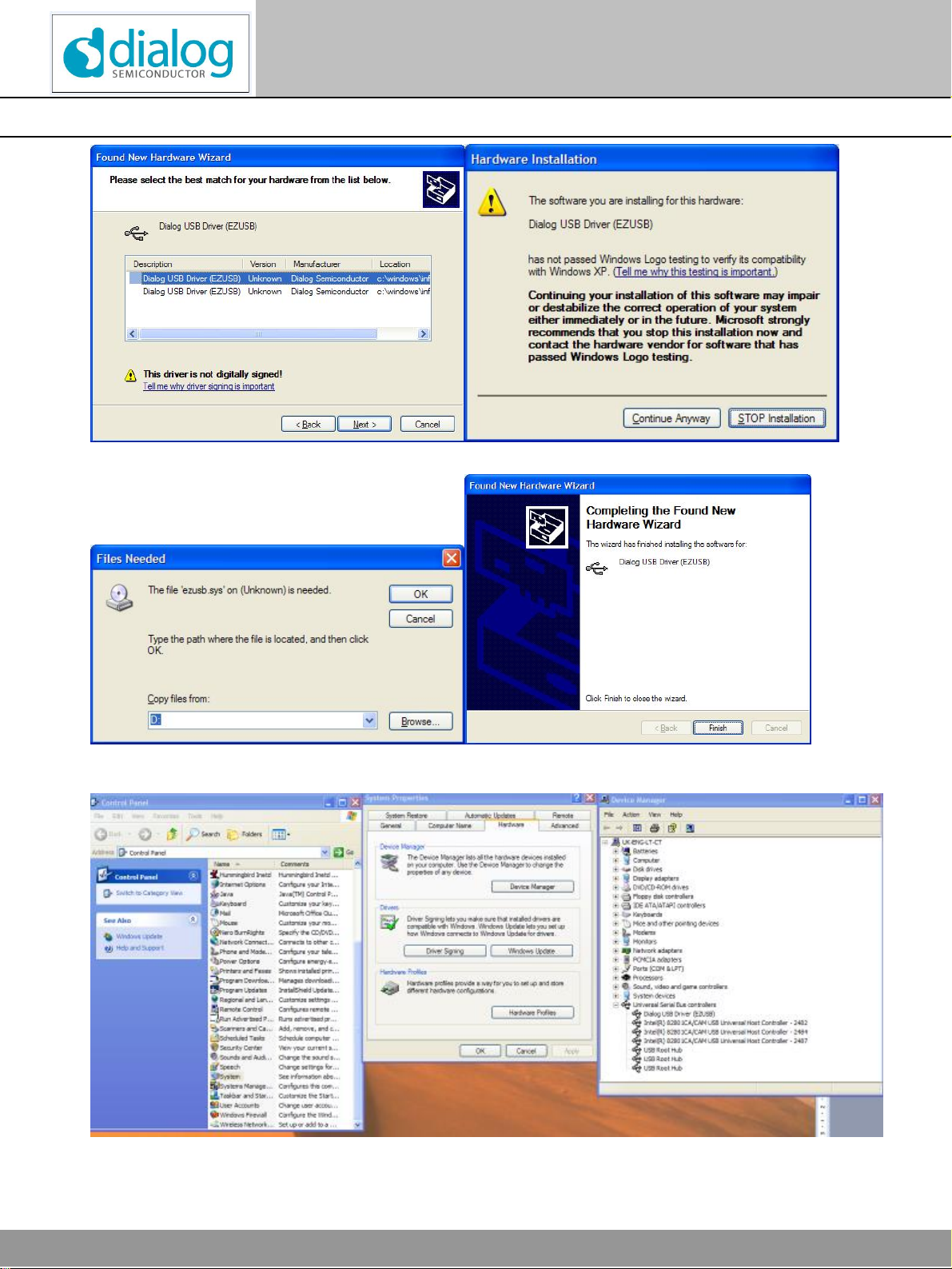
InserttheCD containing thesoftware.If theinstallationdoesnotstart automatically,runtheprogram‘setup.exe’fromthe
CD containingthesoftware.(Thiswillbefound inthedirectory‘Software’ontheCD).Anautomatedscriptwillinstallthe
programonyourPC.Bydefault, thedirectoryC:\DialogSemiconductor\DisplayControllers\DA852Xwillbeusedto
(hopefully)bemorecompatiblewithWindowsVista.
PlugintheUSB cable,and Windowswilldetect theUSB device. It willpromptforthedrivers,whichshouldbe
automaticallylocatedon therootdirectoryoftheCD. Thesetup fileisDlgezusb.inf.
Thefollowingimagesshowtheprocedurestepbystep.
Firststep-Select“No,notthistime”then“Next”Second step–Select“Installautomatically”
©Dialog Semiconductor2008. Allrights reserved.
All brand and product names aretrademarksor servicemarks of their respectiveowners. Printed in Europe. DA852x-UG02-608 Page10of47
UserGuideRelease2.0
DA852XEInkEvaluationKit
Display Controllers
Thirdstep–Select Dialog USBDriverFourthstep–“ContinueAnyway”
Fifthstep–(notalwaysproduced)If prompted,select SixthStep–Select“Finish”.
D: (oryourCDROMdriveletter)
©Dialog Semiconductor2008. Allrights reserved.
All brand and product names aretrademarksor servicemarks of their respectiveowners. Printed in Europe. DA852X-UG02-608Page11of47
UserGuideRelease2.0
DA852XEInkEvaluation Kit
Display Controllers
Ifinstalledcorrectly, DialogUSB Driver(EZUSB)shouldbelistedonDeviceManagerasshownabove.
IfyouareusingWindowsXP,youmayget amessagesayingthataUSB2deviceisattachedtoaUSB1.1port.Thiscan
safelybeignored.
TouninstallthesoftwarepleaseusetheWindows‘Add/RemovePrograms’functionthatcanbefoundunder‘Start’-
>’Settings’->’ControlPanel’.
Note: Thisproceduremayneedtoberepeatedif theUSB Interfaceispluggedintoadifferent USB Port.Thisisa
“feature”ofWindows, whichidentifiesaUSBdriveras“belonging”totheportonwhichit wasinstalled.
ThesoftwarehasnotbeentestedextensivelyonWindowsVista, butno problemshavebeenidentifiedwiththesoftware
ordevicedriverinstallation.If thesoftwareisinstalledintothe“ProgramFiles”directory,it maynot bepossibletoedit
text files,sincetheseare“virtualised”intotheUsershomefolder. Thesoftwarewill(probably)requireanadministrator
priveligetoinstall.
3.1.3Control Panel
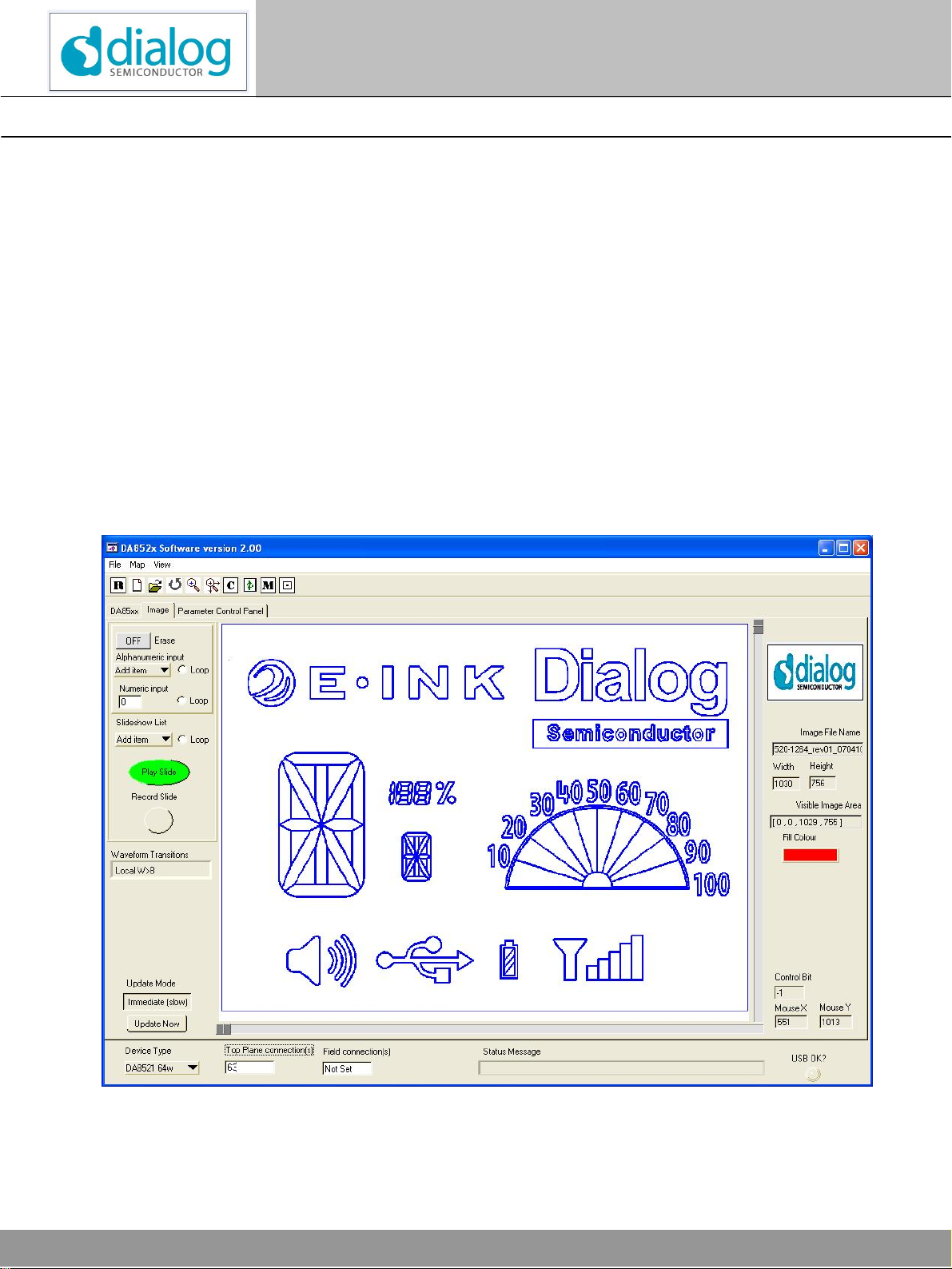
Run the“DA852X”programbyclickingtheshortcutintheStart menu Start>Programs>Dialog Semiconductor>Display
Controllers>DA852X_nnn.exe(wherennn isthelatestversionnumber). Thebest settingforthePCdisplaysizeis
1024x768 pixels..It isimportanttonotethat adisplaysizeotherthantherecommendedsetting mayaffect thewayin
whichthepanelsappear.It willoperatewithbothnormalandlargefonts.
Figure3.InitialInterface

©Dialog Semiconductor2008. Allrights reserved.
All brand and product names aretrademarksor servicemarks of their respectiveowners. Printed in Europe. DA852x-UG02-608 Page12of47
UserGuideRelease2.0
DA852XEInkEvaluationKit
Display Controllers
3.1.4Interface Description
Theinterfacecomprisesthree tabbedpanels, DA852X,Image, ParameterControlPanelandsomecommoncontrols
DeviceType, TopPlaneConnection(s), FieldConnection(s),StatusMessage, and USBindicator.
Theinterfacehasfilemenu items,toolbariconsandkeyboardshortcutsformanyofthecommonfunctions.
Hoveringthemouseovercontrolsontheselectedpanelproducesfloating“tooltip”text withhelpfuldescriptionsofthe
controls.
3.2CommonControls
3.2.1DeviceType
ThispulldownmenuselectsacurrentProject, orallowsthecreation ofanewUserProject.Wehavepre-definedthefirst
4andincludeddataappropriatetothosedevicesizes.
Theuserwillnormallyselect“AddItem”,(oralternativelyselect“NewProject”ontheFileMenu, or“StartaNewProject”
on thetoolbar),provideameaningfulprojectname,andprovidethenumberof outputsegmentsinuseforthatproject.
Thisnumbercan bemore(implyingacascadeconnection)orless thattheoutputsavailableonthechip.
AsubdirectoryundertheDatadirectoryiscreatedtoholdalltheinformationrelevanttothisproject.
Onceaprojecthasbeencreated,it isaddedtothepulldownmenu,and willbereloadedwheneverthesoftwareis
started.
3.2.2Top PlaneConnection(s)
Theusermust manuallyentertheoutputconnectedtothetop planeconnection. Usuallythisiseasilyavailablefromthe
documentationprovidedwiththedisplaypaneland byinspectionofthedisplaypaneltoPCBinterface.If not, itcanbe
deduced, see Tutorial.
Wherethephysicaldisplayhasmultipleconnectiontabs,it ispossiblethateachtab hasaconnection tothetopplane
and field(background). IfeachtabwereconnectedtoanEvaluation board,twooutputswithoppositephasecouldbe
shortedout. Thereforethesoftwareallowsmultipletopplanestobeentered, e.g.“63,127,191”. Alltheseoutputswillthen
switchinsynchronism.
3.2.3FieldConnection(s)
Enteringinformationhereisoptional,butifmultipletopplaneconnectionsabovearebeing used,thisallowsmutiplefield
connectiontobeenteredalso. Theconnectionsenteredwill switchtogetheralways.
3.2.4StatusMessage
Thismessageboxwilldisplaythecurrentmodeofthesoftware. ThisisespeciallyusefultocommunicateMapentryand
zoommodes.
3.2.5USBOK?Indicator
Agreenlighthereshowsthat theUSB interfaceisfunctioningcorrectly.
Ifofflinemodeisinuse(offline=1 in[Setup]section ofDA852X.ini)thenthesystemwill temporarilygoonlineandoperate
thehardwareifavailable.Theofflinemodeisnotcancelled,however, soarestart ofthesoftwarewill returntooffline
mode.
3.3DA852XPanel
Thisisthesimplestinterfacetotheattachedpanel,showingthecurrent state ofthesegments. Thenumberofsegments
shownreflectsthesizeofthedeviceselected. Forlargenumbersofsegments,scroll barsappeartoallowaccess tothe
highernumbers.

©Dialog Semiconductor2008. Allrights reserved.
All brand and product names aretrademarksor servicemarks of their respectiveowners. Printed in Europe. DA852X-UG02-608Page13of47
UserGuideRelease2.0
DA852XEInkEvaluation Kit
Display Controllers
Thesoftwareoperatesbykeeping trackofthe state ofthepanel,i.e.whichsegmentsareblackandwhicharewhite.
Operationofthesegmentcontrols,imageinterfaceandsequencesresultsinachangefroman old_state toa
new_state, undercontrol ofawavefromselection,whichaffectshowthetransition looks.Uponcompletionofthe
transition, new_state iscopiedtothe old_state. Thestateof asegmentdoesnotindicatewhetheritsphysicaloutput
connectionishigh orlow.
3.3.1DirectControl
Clicking onanycontrolwillturnthatsegmentdarkorlight. Ifthedisplayhasbeenmapped,theappropriatesegmentwill
beshowninthesmallthumbnailimagealongsidethecontrols.
Pleasenotethatthesestatesdonot necessarilyindicatetheoutputvoltageofthesegmentoutputs.
Thesegmentdesignatedasthetopplaneconnection,orconnections,aregreyedout and cannot beactivated
separately.Itwill,however,becontrolledbythesoftware.
Ifyouhavenotusedthesoftwarebefore,thedevicetypeselectedwillbeDA8521(a64 segment device). Animageofa
suitableEInkdisplayappearsalongside.
3.3.1.1DirectInput
TheDirectInputboxallowsentryofastringofhexdigitsrepresenting theindividualstates.Thelengthofthisstring
shouldbe numberofstates/4 .If thelengthofthestring enteredisless thanthis,thecharactersenteredwill affectthe
lowest numberedstates.Thelengthofthestringthatcanbeenteredislimitedautomaticallyto numberofstates/4 .
Thisboxhasafewpracticaluses,suchasproviding afast wayoffilling all orpartof theimage(e.g.enterFFFFFF…
untiltheentrylimit isreached),orenteringastringthatiscut-and-pastedfromtheuser’sownsoftwaretoverifycorrect
operation duringsystemdevelopment.
3.3.1.2Hex equivalent
TheHexequivalentboxshowsthecurrent output stateexpressedinhexadecimal.Itcan beusefulduring software
developmenttocut-and-pastethisstringintoexternalsoftware.
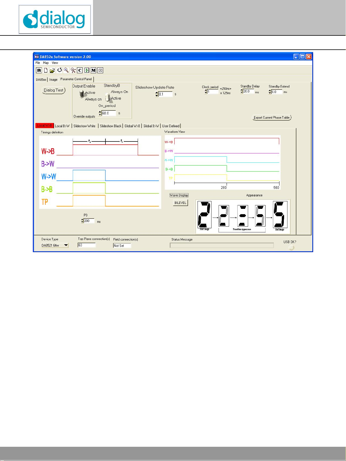
3.4Parameter Control Panel
Thisisusedtoadjustsettingswhichaffecttheappearanceof thepanelbetweenstatechanges,tochangeslideshow
and signaltimingsand toaccesstestfeatures.
©Dialog Semiconductor2008. Allrights reserved.
All brand and product names aretrademarksor servicemarks of their respectiveowners. Printed in Europe. DA852x-UG02-608 Page14of47
UserGuideRelease2.0
DA852XEInkEvaluationKit
Display Controllers
Figure4.ParameterControl Panel
Theuserisabletoadjustdisplaycontroltimings,andactivatethechargepumpforalongerperiodtomake
measurementsetc.
ClockPeriodThisadjuststhetimingoftheserialinterface.Aclock periodof 5willresultineachbitbeingtransmitted
at arateof 1.14Mb/s(250ns+5x125ns).Themaximumrateusingthissoftwareis4Mb/s.Thevalue
shouldshouldbeadjustedtotheminimumvalueconsistentwithcorrect transferacrossthehardware.
StandbyDelayThisadjuststheamountoftimethatthe15voltgeneratorisallowedtochargetoitsfinalvaluebefore
dataissentandthedisplayisenabled. Atypicalfigureis20msforVDD=3.3v.It isonlyrequiredthat
theoutputvoltagehasreacheditsworkingvoltagebeforethedisplayisenabled. Thiscanbeverified
on anoscilloscopebymonitoringpinsBLANKandV15_OUT.
StandbyExtend Thisadjuststheamountoftimethatthe15vgeneratorisenabledafterthetransitioniscomplete. This
shouldbesmall,andcanusuallybezerotoconservepower.
SequenceUpdateRateThissetstherateat whichnewsequencesaredisplayedwhenin“Loop”mode.Thiscontrol
can beupdatedfromwithinsequencefiles(see Section “TheSlideFile“).
StandbyBSwitchingthistothe“AlwaysOn”position allowsthechargepumptobeenabledfortheperiodshown
intheboxbelow.Itwillrevert backattheend oftheperiod. Thisisforprotectionof anyattached
display,toavoidpowerbeingappliedforaprolongedperiod. Thiscontrolisonlyusedduring
development,investigatingparameterssuchasthelevelof 15vripple.

©Dialog Semiconductor2008. Allrights reserved.
All brand and product names aretrademarksor servicemarks of their respectiveowners. Printed in Europe. DA852X-UG02-608Page15of47
UserGuideRelease2.0
DA852XEInkEvaluation Kit
Display Controllers
OutputEnableThiswilloverridetheprogrammed EnablePeriodtoenablethe outputdrivepermanently. Thisallows
measurment andinspectionoftheoutput drivesduringdevelopment.
Dialog TestAllowsaccess tointernaltestmodesand automatedtestforDialog Semiconductoruse.Requires
passwordwhichwillnotnormallybeprovided.
Export CurrentPhaseTableThiswillgenerateatext filecontainingthecurrentphasetable.
SeeSection 5WaveformPhaseTable
3.4.1WaveformSelection
Eachtabcontainstheparametersnecessarytocontrol6different predefinedtypesoftransitionappearance, andone
typewhichcanbedefinedbytheuser,see 5WaveformPhaseTable.Selectingatabchangesthestatetransition tothat
mode. Themodeselectionisstoredintheprojectconfigurationfile.
Thewaveformcanbechangedtemporarily(i.e. notstoredintheconfigurationfile)undercontrolofsequenceevents, see
section3.5.4“TheSlideFile”.
Detailedselectionof theparameterswillnot becoveredinthissection.
TheusershouldensurethattheparametersT0,T1and P0arelong enoughtoallowcompleteswitchingofthesegment.
Ifthevaluesaretoo short,agreylevelwillbeproduced. Thedefault is280ms.
Thetypesare:
LocalWhitethenBlack Thisisalocalupdatewaveform. Onlythepixelsthathaveadifferent endingstatefromtheir
startingstateswitch.
Theblack-to-white(B->W)transitionhappensbeforethewhite-to-black(W->B)transition.Thiswaveformisusefulfor
non-flashyupdates; however, repeatedupdatesorlong dwelltimesinbetweenupdatesmaycauseimageartifacts.
LocalBlackthenWhite Thisisalocalupdatewaveform. Onlythepixelsthathaveadifferent endingstatefromtheir
startingstateswitch.Thisisbetterusedforinversemodeoperation.
Theblack-to-white(B->W)transitionhappensbeforetheblack-to-white(B->W)transition.Thiswaveformisusefulfor
non-flashyupdates; however, repeatedupdatesorlong dwelltimesinbetweenupdatesmaycauseimageartifacts.
SlideshowWhite
Thisisaslideshowwaveform.Everytransition travelsthroughwhite.
Thiswaveformgivesaclean transitionappearancewhenswitchingcharacters.Thisisusefultousewhenupdating
alphanumericdisplayssinceitcompletelyerasestheoldinformationbeforethenewinformationisdisplayed.Thisis
recommendedforusewithwhitebackgrounds.
SlideshowBlack Thisisaslideshowwaveform.Everytransitiontravelsthroughblack.
Thiswaveformgivesaclean transitionappearancewhenswitchingcharacters.Thisisusefultousewhenupdating
alphanumericdisplayssinceitcompletelyerasestheoldinformationbeforethenewinformationis
displayed.Thisisrecommendedforusewithinversemodeoperation.
GlobalWhitethenBlack Thisisaglobalupdatewaveform. Allpixelsswitchduring atransition.
Thedisplaywillswitchtowhitethentoblack,beforedisplayingthefinalimage. Thiswaveformisusefultoclearimage
artifactsfromthedisplay. Withoptimalsettings,itprovidesthe best imageperformance.
GlobalBlack thenWhite Thisisaglobalupdatewaveform. Allpixelsswitchduring atransition.
Thedisplaywillswitchtoblackthentowhite,beforedisplayingthefinalimage. Thiswaveformisusefultoclearimage
artifactsfromthedisplay. Withoptimalsettings,itprovidesthe best imageperformanceforinversemodeoperation.
UserDefined Thisallowstheusertoimporthisownphasetable(see 5WaveformPhaseTable).Thetransitionwill be
shownasawaveformorbi-levelview. Thisisobviouslyanadvancedfunction,butcanbeusefulduringsystem
development.

©Dialog Semiconductor2008. Allrights reserved.
All brand and product names aretrademarksor servicemarks of their respectiveowners. Printed in Europe. DA852x-UG02-608 Page16of47
UserGuideRelease2.0
DA852XEInkEvaluationKit
Display Controllers
Thewaveformsareshownintwopossiblemodes:
Wave Mode showsthedrivewaveformindifferentialmode.Thisisthevoltagedifferencebetweenthesegmentand the
top planeconnections. Apositivevaluedrivesthesegmenttowardsblack, andanegativevaluedrivesthesegment
towardswhite. Theassumptionhereisthatthetopplaneisalways zero.
Thisvisualisationofthetransition can betheeasiesttosee the effect ofparameterchanges.
Notethatthedevicedriversdoesnotusenegativevoltages,sothesewaveformsareconceptual.
Bilevel Mode showsthewaveformaslogicvalues,andincludescontroloverthetopplane. Thismodeisclosesttowhat
isactuallyocurringatthedevicedriverpins.Thismodeisusefultocreateandvisualisecustomphasetables(see
Appendix2)astheorderofthestatechanges(W-B, B-W,W-W,B-B,TP)arethesameasthoseinthephasetable.
3.4.2FileMenu
File>NewProjectKeyboardshortcut Ctrl+N. Promptstheuserforaprojectnameandnumberofoutputs.
Createsdirectoryforprojectname,and .iniconfigurationfiletostorechanges.
File>OpenProjectKeyboardshortcut Ctrl+O.Displaysalistofcurrent projects,allowingselectionofnew
project.
File>ImportProjectAllowsanexistingdirectorytobeaddedtotheProjectlist.Thismightbeaprojectpreviously
deleted, oradirectorymanuallycopiedfromanotherlocation.Thedirectorymustcontainan
.inifilewiththesamenameasthedirectory.
File>CopyProjectAllowsthecreationof acopyoftheexistingselectedproject withanewname.Thisis
especiallyusefultoallowadifferent set ofslidefilestobeselected, oradifferent mapfileto
linktodifferent hardware.
File>DeleteProjectDisplaysalistofcurrentprojects. Selecttotheleft ofaprojecttodeletethatproject fromthe
list.
Apromptboxallowscancellingoftheselectionifperformed inerror,withafinalconfirmation
afterward.
File>LoadImageKeyboardshortcut Ctrl+I. Opensadialogboxtoselect anexisting WindowsBitmap(.bmp)
image, whichshouldresideintheproject directory.Right-clickinghereallowsvarious
navigationandcopy-pasteactivities.
File>LoadMapKeyboardshortcut Ctrl+P.Opensadialogboxtoselectanexistingmapfile(.map). Foranew
project thiswouldnot exist,but itcouldbeacopyofanexisting fileforasimilarproject.Right-
clickinghereallowsvariousnavigationandcopy-pasteactivities.
File>ExportPhaseTableThiswritesthecurrentphasetabletoaselectedfile.Thisphasetablemaybemodifiedto
achieveanewtransition appearanceortoremovedisplayartifacts.See Section 5.
File>Reset DisplayThisresetsthedisplaybyignoringitscurrentstate,andsettingthedisplaytoall-white, all-
black,thenall-whiteagain.Thisisperformed ifdevelopmentand testinghasresultedingrey
orpartiallyonsegmentswhichcannot beclearedbyaView>Clearcommand.
TheReset commandwillusuallyresult inawhitedisplayagain. Repeatifnecessary.
IftheInvertModehasbeenset, thedisplaywillfinishintheblack state.
File>ExitKeyboardshortcut Alt+F4.Shutsdownthesoftware,leaving thedisplayintact.

©Dialog Semiconductor2008. Allrights reserved.
All brand and product names aretrademarksor servicemarks of their respectiveowners. Printed in Europe. DA852X-UG02-608Page17of47
UserGuideRelease2.0
DA852XEInkEvaluation Kit
Display Controllers
Map>Load NumberOffset FileThisspecifiesthenumberoffsetfiletobeusedtofacilitatesimpleentryofnumberson
thedisplay
Map>Load AlphaOffsetFileThisspecifiesthealphanumericoffset filetobeusedtofacilitatesimpleentryof
alphanumericstringsonthedisplay
Map>Undo LastMap EntryKeyboardshortcut Ctrl+Z.Inmap entrymode, thishighlightsthelast boxtobeenteredand
allowsittobedeleted.
Edit>MapEntryModeKeyboardshortcut Ctrl+L. TogglesMap EntryMode
View>RefreshKeyboardshortcut F5.RefreshthePCdisplaywithnochange tostatus.
View>InvertTogglesInvert mode. Thiswill invertthecurrentdisplayandallslides.
View>ZoomZoomintoimagearea.
View>ZoomFull Showentireimagearea
View>Map Keyboardshortcut Ctrl+M.Togglesviewingof mapboxeson theimage
View>Fill ThistogglesFillmode. Normalmodeisenabled, whichallowsthePCscreentoreflectthe
physicaldisplay.Thefill colourisselectable.
View>ClearKeyboardshortcut Ctrl+Y. Clearstheimageareaanddisplay.
3.4.3Toolbar
Reset DisplayidenticaltoFile>Reset Display
Start NewProjectidenticaltoFile>NewProjectandAdd IteminDeviceTypepulldown
OpenProjectidenticaltoFile>OpenProjectandselecting IteminDeviceTypepulldown
Undo identicaltoEdit>UndoLast MapEntry
ZoomidenticaltoView>Zoom
ZoomFullidenticaltoView>ZoomFull
ClearidenticaltoView>Clear
RefreshidenticaltoView>Refresh
ShowMapidenticaltoView>Map
Map EntrymodeidenticaltoMap>MapEntryMode
©Dialog Semiconductor2008. Allrights reserved.
All brand and product names aretrademarksor servicemarks of their respectiveowners. Printed in Europe. DA852x-UG02-608 Page18of47
UserGuideRelease2.0
DA852XEInkEvaluationKit
Display Controllers
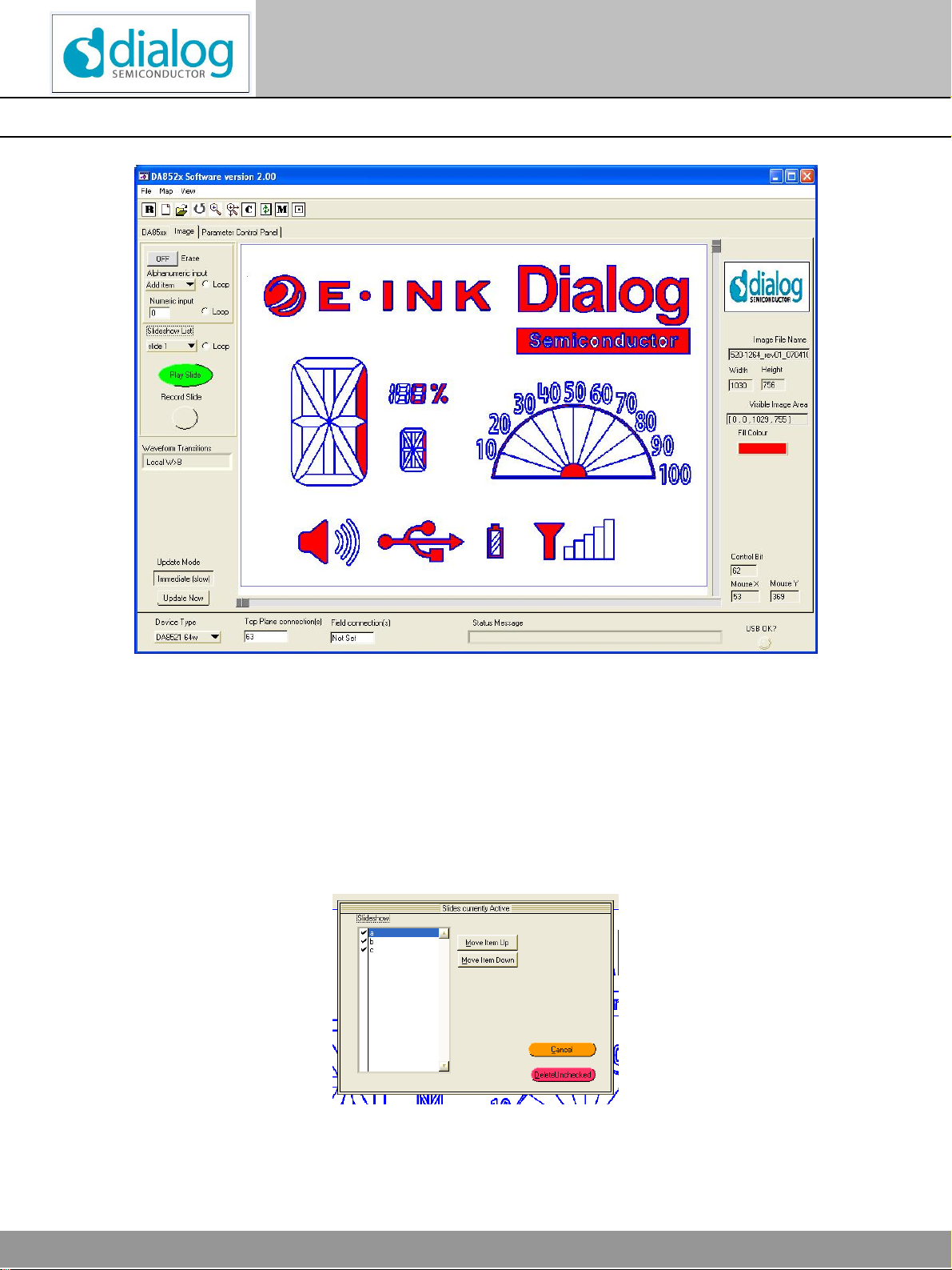
3.4.4ImageControls
Figure5.Imagepanelshowing loadedbitmapandfilledsymbols
AlphanumericInputSelecting “Additem”allowsentryofanalphanumericstring, whichwillbedecodedintoa
seriesofslides.If the“Erase“buttonisoff, thealphanumericstring isaddedtotheexisting
display, elsethescreenisclearedbeforedisplay.
Selectinganexisting iteminthelistdisplaysthatitem. Right-clickingonthecontrolbringsup
acontrolpanel,whichallowsreorderinganddeletionof alphanumericitems.
Click onthetext tohighlight theitem,thenMoveItemUporDowntoreorderitinthelist.
Clicking onthecheck markbesideanyalphanumericwilltoggletheselection.Anyunchecked
itemswill beremovedafterpressingthe“DeleteUnchecked”button whichclosesthepanel.
Figure6.AlphanumericControlpanel

©Dialog Semiconductor2008. Allrights reserved.
All brand and product names aretrademarksor servicemarks of their respectiveowners. Printed in Europe. DA852X-UG02-608Page19of47
UserGuideRelease2.0
DA852XEInkEvaluation Kit
Display Controllers
AlphanumericloopChecking thisitemcausesallthealphanumericitemsinthelisttobedisplayedendlesslyuntil
it isunchecked
NumericInputAllowsentryofasinglenumber, whichwillbedecodedintoaseriesofslides.If the“Erase“
button isoff,thenumberisdisplayedontop oftheexisting display,elsethescreeniscleared
beforedisplay.
NumericLoop Checking thisitemcyclesallnumbersup to999endlesslyuntil itisunchecked.
SlideshowListSelecting “Add item”allowsselectionof multiple, previouslyrecordedsequenceswhichwill
beaddedtothelist. ThecontrolpanelFigure7isthenactivetoallowreorderingorfurther
selection. Selectingan existingiteminthelist displays thatitem.
Alternatively,right-clickingonthecontrolbringsup thecontrolpanel,Figure7,toallow
addition,reordering,temporaryselection anddeletion ofsequenceitems.
Click onthetext tohighlight theitem,thenMoveItemUporDowntoreorderitinthelist.
Clicking onthecheck markbesideanyalphanumericwilltoggletheselection.
Furtherfilesmaybeaddedtothelist bypressingthe“AddFiles”button.
Anyuncheckeditemswill betemporarilydisabledafterpressing the“DisableUnchecked”or
“OK”buttonwhichclosesthepanel.
Anyuncheckeditemswillberemovedafterpressing the“DeleteUnchecked”button which
closesthepanel.
Selecting “Cancel”closesthepanelwithnochangesmade.
Allchangesarereflectedintothesequencelist box, andalsostoredintheconfigurationfile.
Figure7.Sequence ControlPanel
EraseCausesAlphanumericandnumericinputstobeprecededbyaClearcommand. Useeraseif
thealphanumericsornumericsaresimplybeingloopedindependently,butturnitoff if
alphanumericornumberinputarebeingusedaspartof aslide creation.
SlideshowLoopChecking thisitemcausesalltheslideshowitemsinthelisttobedisplayedendlesslyuntilit
isunchecked. ThetimebetweensequencesiscontrolledbytheSequenceUpdateRateinthe
Configurationpanel.
PlaySlideOpensaDialogboxtochoosesinglesequencetodisplay.

©Dialog Semiconductor2008. Allrights reserved.
All brand and product names aretrademarksor servicemarks of their respectiveowners. Printed in Europe. DA852x-UG02-608 Page20of47
UserGuideRelease2.0
DA852XEInkEvaluationKit
Display Controllers
RecordSlideClicking thisstartsrecordingofallmouseclickswhichtogglesegmentoutputs.Thecontrol
turnsredtoindicaterecordingmode. Clicking RecordSlideagaincausestherecordingmode
tofinish,openingadialog boxtopromptafilenamefortheslide. Itisnot necessarytoaddthe
.txtsuffix,thiswillbedoneautomatically.If anexisting fileisselected, theoptiontoReplace
orCancelisprovided.
WaveformTransitionsIndicatesthetypeof transitionsinuse. See Section 3.4.1
UpdateModeIfUpdateModeisSynchronous, mouseclicksarenottransmittedimmediatelytodisplay.If
modeisImmediate,mouseclicks aretransmittedimmediately, butthiscouldresultinfairly
slowresponseduetotheEnabletimeofthedisplay.ThedefaultmodeisImmediate.
UpdateNowUpdatesthedisplaywithstoredmouseclicksifmodeisSynchronous.
3.4.5ImageInformation
ImageFileNameDisplaysImagefilename
Width, HeightDisplaysImagefilewidthandheightinpixels.
VisibleImageAreaDisplaystop leftandbottomrightcoordinatesofviewedareaofimage. Thisisupdatedduring
zoomoperations.
ControlBitDisplayssegmentoutputassociatedwithclickedareaoftheimage.If areaisnotassociated
withasegmentinthemapfile, displays-1
MouseX, MouseYDisplaysposition of mouseclickonthepanelinBitmapunits. 0,0isinthetop leftofthe
image.
ScrollBarsThesecan beusedwhentheimageiszoomedintopantheimageverticallyorhorizontally.
Thescrollbarswillnotallowtheimagetobescrolledpast thelimitsofthebitmap.
Fill ColourThisallowsmodificationof thecolourwhichwillbeusedtoinfill thesymbolsonthePC
display.Thisshouldnotbethesamecolourastheoutlineofthesymbols.
This manual suits for next models
4
Table of contents
Other Dialog Semiconductor Motherboard manuals

Dialog Semiconductor
Dialog Semiconductor GreenPAK Advanced UM-GP-002 User manual

Dialog Semiconductor
Dialog Semiconductor DA7212 User manual

Dialog Semiconductor
Dialog Semiconductor DA1468 series Installation and operating instructions

Dialog Semiconductor
Dialog Semiconductor DA1468 series User manual

Dialog Semiconductor
Dialog Semiconductor UM-GP-007 User manual

Dialog Semiconductor
Dialog Semiconductor DA9155M User manual

Dialog Semiconductor
Dialog Semiconductor DA16600 User manual

Dialog Semiconductor
Dialog Semiconductor SLG46824 Operating instructions


