Dialog Semiconductor DA9155M User manual

Company confidential
User manual
DA9155M Getting Started with
Evaluation Board
UM-PM-010
Abstract
This document describes the hardware and software used by Dialog Semiconductor to test and
evaluate the DA9155M slave battery charger.
The hardware solution is based on PCB numbered 287-06-A.
The software uses a PC operating Windows 2000/XP/Vista/Windows 7 ™ with USB (1.1, 2.0 or 3.0)
interface.
The software permits configuration of the device using one pre-defined templates, read and
operations to all control registers while monitoring device status.
The section ‘Quick Start Tutorial’ provides an abbreviated quick start guide with a practical
configuration example on how to run the evaluation kit.

UM-PM-010
DA9155M Getting Started with Evaluation Board
Company confidential
User manual
Revision 1.0
11-10-2015
UM-PM-010
2 of 19
© 2015 Dialog Semiconductor
Contents
Abstract................................................................................................................................................ 1
Contents............................................................................................................................................... 2
Figures.................................................................................................................................................. 2
Tables ................................................................................................................................................... 3
1Terms and definitions................................................................................................................... 3
2References..................................................................................................................................... 3
3Introduction.................................................................................................................................... 4
4Board recommended operating conditions................................................................................ 5
5DA9155M Performance Board Hardware .................................................................................... 6
5.1 DA9155M Slave charger layout ............................................................................................ 7
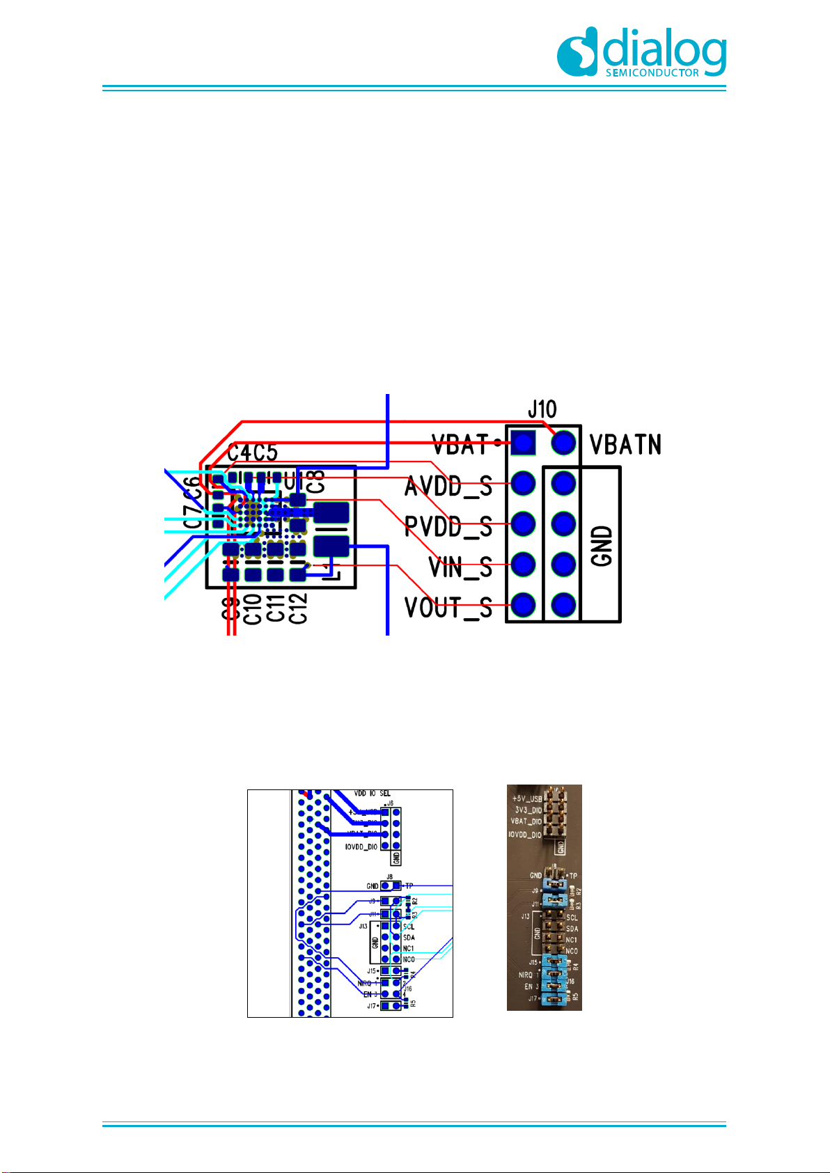
5.2 Slave charger multi-test point J10 connector........................................................................ 8
5.3 Digital I/O board connectivity headers .................................................................................. 8
5.4 Transient injection points ...................................................................................................... 9
5.5 Connectivity........................................................................................................................... 9
6Hardware requirements .............................................................................................................. 10
6.1 Input voltage supply............................................................................................................ 10
6.2 Battery voltage .................................................................................................................... 10
7DA9155M Performance Board Graphical User Interface......................................................... 11
7.1 Software installation............................................................................................................ 11
7.2 GUI overview....................................................................................................................... 12
8Quick start tutorial guide............................................................................................................ 16
Revision history................................................................................................................................. 18
Figures
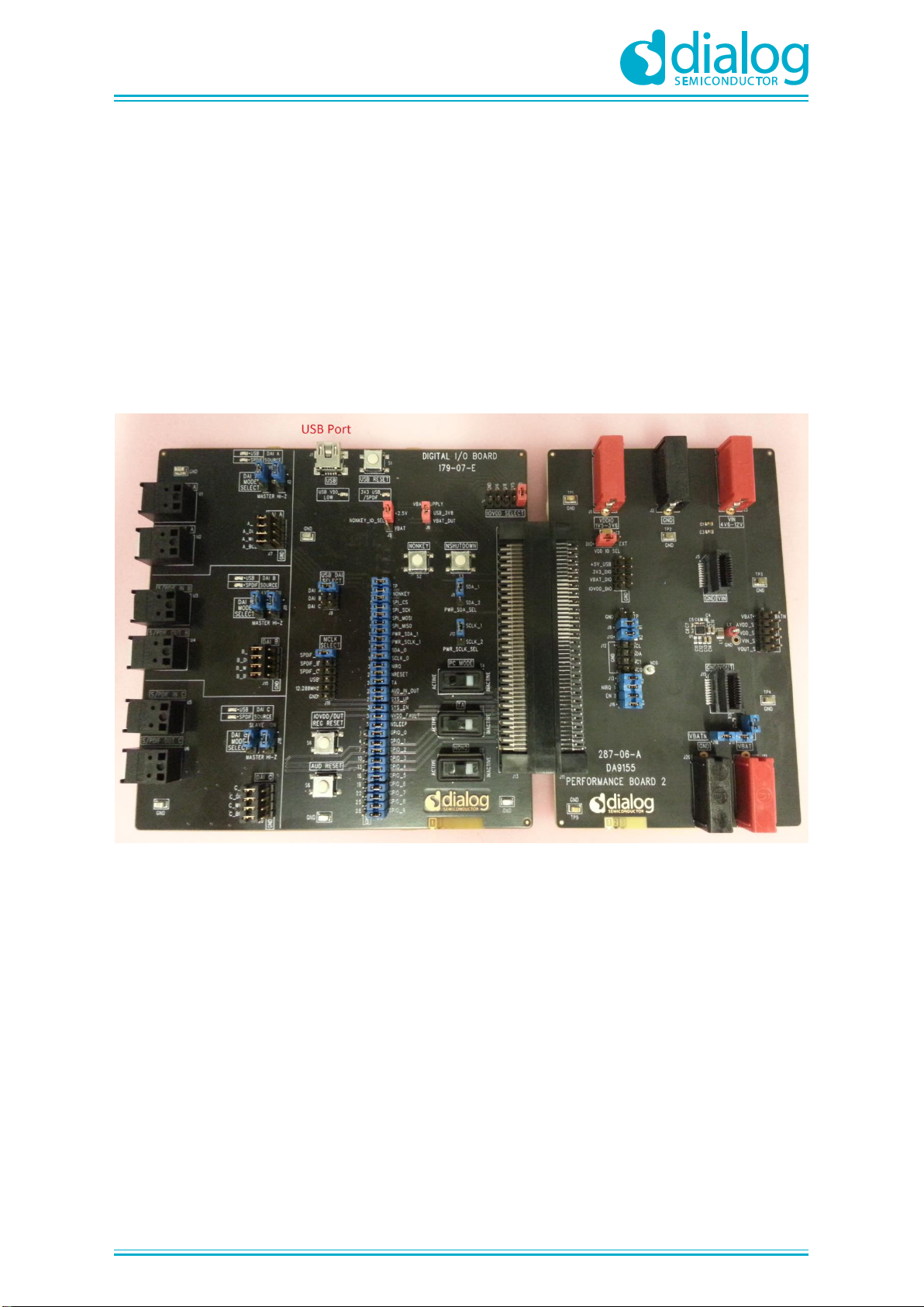
Figure 1: DA9155M Performance Board (top view) .............................................................................. 4
Figure 2: Functional overview ............................................................................................................... 6
Figure 3: PCB Layout for DA9155M...................................................................................................... 7
Figure 4: DA9155M Performance Board Layout................................................................................... 7
Figure 5: Test point J10 header ............................................................................................................ 8
Figure 6: DIO connectivity headers (a) Layout view (b) Default jumper settings.................................. 8
Figure 7: DIO and DA9155M Performance board................................................................................. 9
Figure 8: DA9155M Evaluation GUI Installation File........................................................................... 11
Figure 9: DA9155M GUI Software Licensing and Installation............................................................. 11
Figure 10: DA9155M GUI Installation Path......................................................................................... 11
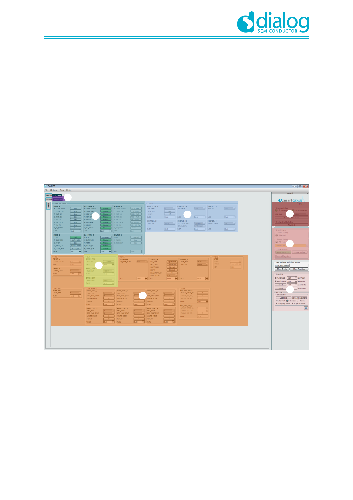
Figure 11: GUI Overview Screen ........................................................................................................ 12
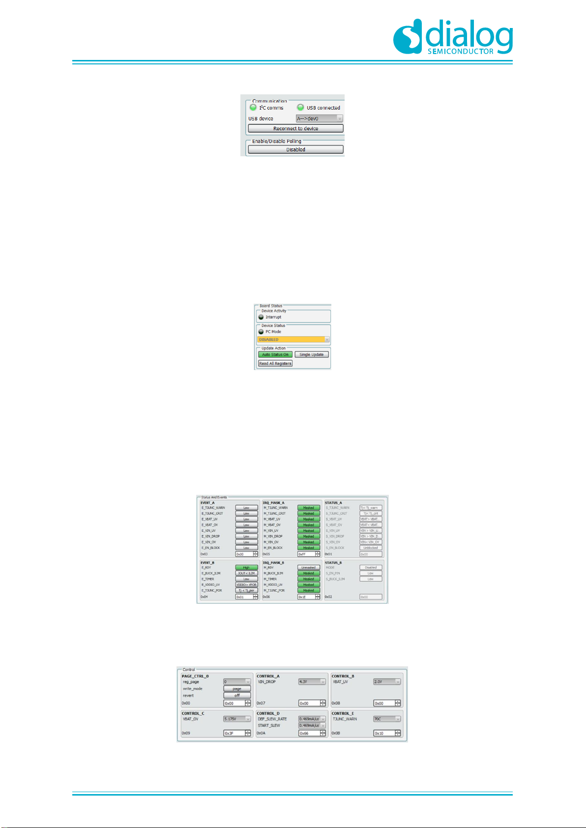
Figure 12: Active Communication Indicator......................................................................................... 13
Figure 13: Board Status Indicator........................................................................................................ 13
Figure 14: Status and Events shown in GUI ....................................................................................... 13
Figure 15: Control Registers in GUI .................................................................................................... 13
Figure 16: Buck converter control registers......................................................................................... 14
Figure 17: Raw I/O and File I/O GUI Controls..................................................................................... 14
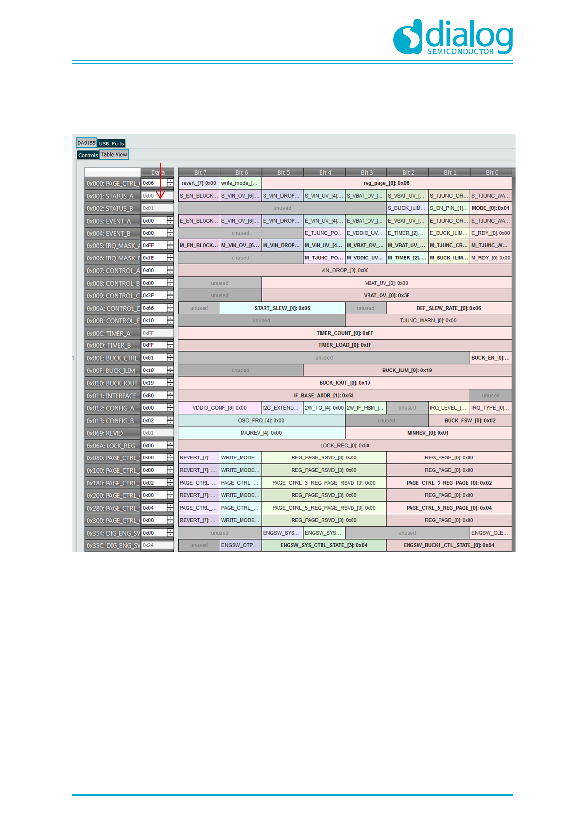
Figure 18: DA9155M GUI using the Table View ................................................................................. 15
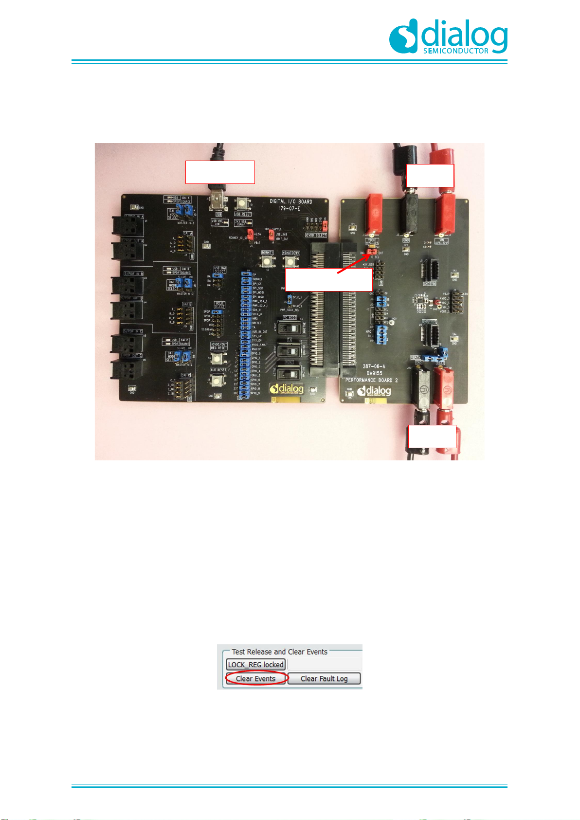
Figure 19: DA9155M Performance Board Full Setup.......................................................................... 16
Figure 20: Clear Events button............................................................................................................ 16
Figure 21: Configure the output current .............................................................................................. 17
Figure 22: Enable Buck converter button............................................................................................ 17

UM-PM-010
DA9155M Getting Started with Evaluation Board
Company confidential
User manual
Revision 1.0
11-10-2015
UM-PM-010
3 of 19
© 2015 Dialog Semiconductor
Tables
Table 1: DA9155M Performance Board recommended operating conditions....................................... 5
Table 2: DA9155M Performance Board overview and descriptions...................................................... 6
Table 3: List of hardware..................................................................................................................... 10
1 Terms and definitions
DAI Digital Audio Interface
DIO Digital Input/Output
DUT Device Under Test
GPIO General Purpose Input Output
GUI Graphical User Interface
I2C/SPI Inter-Integrated Circuit/Serial Peripheral Interface
OS Operating System
PCB Printed Circuit Board
SPI Serial Peripheral Interface
SMU Source Meter Unit
USB Universal Serial Bus
PCB Printed Circuit Board
2 References
[1] DA9155M, Data sheet, Dialog Semiconductor
[2] UG-179-070-D, Digital I/O Board User Guide, Dialog Semiconductor
[3] AN-PM-058 DA9155M PCB Layout Recommendation Application Note, Dialog Semiconductor
[4] 287-06-A00_SCH, DA9155M Performance Board Schematic, Dialog Semiconductor
[5] 287-06-A_PCB, DA9155M Performance Board Layout, Dialog Semiconductor

UM-PM-010
DA9155M Getting Started with Evaluation Board
Company confidential
User manual
Revision 1.0
11-10-2015
UM-PM-010
4 of 19
© 2015 Dialog Semiconductor
3 Introduction
The DA9155M Performance Board is designed evaluate the DA9155M slave battery charger. The
optimised board layout enables testing at full-rated power and measurement of efficiency, current
accuracy, transient response, and thermal performance.
The performance board includes an interface connector to the communication board referred as the
Digital I/O (DIO) board. This DIO board connects the DA9155M to a computer via USB-to-I2C, for
status monitoring and control using the DA9155M Graphical User Interface (GUI).
This document provides an overview of the development board, hardware configuration, and GUI
installation process. The goal of this user manual is to provide the details required to get started with
the evaluation of the DA9155M.
Figure 1: DA9155M Performance Board (top view)

UM-PM-010
DA9155M Getting Started with Evaluation Board
Company confidential
User manual
Revision 1.0
11-10-2015
UM-PM-010
5 of 19
© 2015 Dialog Semiconductor
4 Board recommended operating conditions
Table 1 lists the recommended operating conditions of the DA9155M Performance board. Stressing
the board beyond these ratings may cause permanent damage to the board.
Table 1: DA9155M Performance Board recommended operating conditions
Parameter
Symbol
Min
Max
Unit
Storage temperature
-60
+150
oC
Operating
temperature
TA
-40
+85
oC
Input voltage
VIN
4.3
13.4
V
Supply voltage IO
VDDIO
1.5
3.6
V
Battery voltage
VBAT
0
4.5
V
Battery current
IBAT
0
3
A
Digital I/O
(EN, SCL, SDA, nIRQ)
0
0.7 x VDDIO

UM-PM-010
DA9155M Getting Started with Evaluation Board
Company confidential
User manual
Revision 1.0
11-10-2015
UM-PM-010
6 of 19
© 2015 Dialog Semiconductor
5 DA9155M Performance Board Hardware
The DA9155M board functional overview is shown in Figure 2. The board functionality can be broken
down into the following functions:
Figure 2: Functional overview
Table 2: DA9155M Performance Board overview and descriptions
Section No.
Function Description
1
Device Under Test (DUT) DA9155M slave charger
2
Input Voltage (VIN) terminals
3
Battery Output (VBAT) terminals and battery current sense resistor
4
VDDIO supply selector (DIO vs External)
5
DA9155M multi-test point J10 connector header
6
Digital I/O interface connector
7
Line transient injection point
8
Load transient injection point
9
Digital I/O board connectivity selector (signals SCL, SDA, Enable, nIRQ, TP)
1
6
5
4
3
2
7
8
9

UM-PM-010
DA9155M Getting Started with Evaluation Board
Company confidential
User manual
Revision 1.0
11-10-2015
UM-PM-010
7 of 19
© 2015 Dialog Semiconductor
5.1 DA9155M Slave charger layout
The placement guidelines for PCB layout and trace interconnectivity for the main power components
are shown in the PCB layout section of the DA9155M Datasheet [Ref 1] and also shown in Figure 3
below. The same layout guidelines were followed and implemented for the DA9155M Performance
Board, with the exception of the footprint for additional output capacitors are included in the board for
experimentation purposes.
Figure 3: PCB Layout for DA9155M
It is important to follow the recommended layout guidelines in order to achieve the best efficiency
performance and noise immunity. Particular attention should be paid to the layout of the input
capacitor, inductor and output capacitors, highlighted in Figure 4. From this figure it can be seen that
that the Power Ground ensures that there is the minimal path impedance between the capacitors and
the DA9155M PGND terminals. The layout engineer should review the DA9155M PCB Layout
Recommendations Application Note, see [Ref 3]
Figure 4: DA9155M Performance Board Layout
Note: Only 2
output caps
needed

UM-PM-010
DA9155M Getting Started with Evaluation Board
Company confidential
User manual
Revision 1.0
11-10-2015
UM-PM-010
8 of 19
© 2015 Dialog Semiconductor
5.2 Slave charger multi-test point J10 connector
The multi-test point connector is shown in Figure 5. This connector provides the user access to the
various nodes of the DUT. This connector is only capable of “sensing” voltages and should not be
used for delivering current/voltage to and from the DUT, as the PCB traces can be fused by
excessive current.
The signals available on this header are:
○Battery voltage VBAT sense (using battery Kelvin connection)
○Voltage of the AVDD supply
○Voltage of the PVDD supply
○Input voltage VIN sense
○Output voltage VOUT (measured at DA9155M output capacitor node)
Figure 5: Test point J10 header
5.3 Digital I/O board connectivity headers
The DIO interface connectors select the signals from the DIO board to the DUT board and also
provide test point terminals to monitor the different voltage rails of the DIO board. The jumpers
shown in Figure 6 below indicate the default jumper selection for the digital signals SCL, SDA,
Enable, nIRQ and TP.
Figure 6: DIO connectivity headers (a) Layout view (b) Default jumper settings
(a) (b)

UM-PM-010
DA9155M Getting Started with Evaluation Board
Company confidential
User manual
Revision 1.0
11-10-2015
UM-PM-010
9 of 19
© 2015 Dialog Semiconductor
5.4 Transient injection points
The two injection points are connected to the input voltage and output voltage (J5 and J15). These
can be used to measure the line and load transient response of the DUT. Special transient injection
boards are available (P/N 44-179-168-03-A and 44-179-168-03-B Hammer2 board), but these are
not supplied as part of the standard DA9155M Performance Board kit. Please contact Dialog
Semiconductor for more information on how to obtain one of the transient injection boards.
5.5 Connectivity
To evaluate the features of the DA9155M slave charger, it is necessary to connect the DUT to a
computer to perform status monitoring and configure the device. The DA9155M Performance Board
uses the DIO board as an interface to convert the USB datalink to I2C bus on the DUT.
Figure 7: DIO and DA9155M Performance board
The configuration settings for the DIO board are shown in Figure 7. Ensure these settings match the
board under test. For additional information, schematics, and configuration, see the Digital I/O Board
User guide [Ref 2]

UM-PM-010
DA9155M Getting Started with Evaluation Board
Company confidential
User manual
Revision 1.0
11-10-2015
UM-PM-010
10 of 19
© 2015 Dialog Semiconductor
6 Hardware requirements
The hardware included in the list below can be substituted by equivalent hardware.
Table 3: List of hardware
Item #
Description
Manufacturer
Comments
1
DA9155M Performance Board
Dialog
Semiconductor
2
Digital I/O Board
Dialog
Semiconductor
3
USB Cable
N/A
Type-A Male to Mini Type-B Male
4
Keithley 2308 Battery Emulator
Keithley
Dual output SMU,
Output #1: Connected to VBAT (1)
and
Output #2: Connected to VIN
Note 1 This SMU must be capable of sourcing and sinking current (simulate a battery).
6.1 Input voltage supply
The DA9155M Performance Board is a slave battery charger; this means that the input voltage must
be present in order to enable the DUT. For the initial setup, and example in this document, this is set
to 9 V DC and the current limited to 3 A.
6.2 Battery voltage
The VBAT terminals must be connected to a battery and the battery voltage must be within the
DA9155M under- and overvoltage limits. Otherwise the DUT will enter into a fault condition and the
charging mode will not be enabled until the fault is removed and the fault status registers (Event_A
and Event_B) are cleared, see the DA9155M Datasheet [Ref 1] for more details on the DUT power
modes and/or fault detection.
Before connecting a standard DC power supply to the VBAT terminals, ensure that the DC power
supply is able to source and sink current. Once the DA9155M charger is enabled, current needs to
flow into the VBAT supply. Failure to do so could damage the DC power supply and/or the DA9155M
Performance Board.
In the hardware list Table 3, the Keithley 2308 Battery Emulator Output #1 is connected to the VBAT
terminals. The battery emulator was selected because it is able to sink/source up to 5 A of current
and the input impedance can be programmed between 0 Ωand 1 Ω, in 10 mΩsteps.
There are three options that can be connected to the VBAT terminals:
●Li-Ion battery, the voltage must be within the under- and overvoltage limits as configured in
DA9155M settings (VBAT_UV and VBAT_OV registers)
●Source Meter Unit capable of sourcing and sinking current, such as the Keithley 2308.
●Power supply connected in parallel to a resistive or electronic load. The user must ensure that
the current load is greater than the current supplied by DA9155M, defined by the BUCK_IOUT
register. For example: Power supply output set to 4 V, electronic load set to 1 A and DA9155M
set to 500 mA.

UM-PM-010
DA9155M Getting Started with Evaluation Board
Company confidential
User manual
Revision 1.0
11-10-2015
UM-PM-010
11 of 19
© 2015 Dialog Semiconductor
7 DA9155M Performance Board Graphical User Interface
The user can explore all the features of the DA9155M with the Graphical User Interface (GUI) using
the I2C interface. This includes changing the control settings and monitoring the status/fault of the
DUT.
The user must be aware that the GUI is non-invasive, meaning:
●It will not modify registers contents without user interaction
●I2C periodic communication stops when the “Polling Enabled” button is set to “Polling Disabled”
7.1 Software installation
When the supplied media is inserted into the computer the installation begins automatically. If the
installation does not start automatically, run the program file
‘setup_DA9155M_Evaluation_GUI_AB.0_0_xx.exe’from the ‘Software’ directory on the media. An
automated script installs the program on your PC, and by default, the directory
C:\Dialog Semiconductor\Power Management\DA9155M_Evaluation GUI is used.
To install the software:
1. Run setup_DA9155M_Evaluation_GUI_AB.0_0_xx.exe and click the ‘Next’ button
Figure 8: DA9155M Evaluation GUI Installation File
2. Accept the license agreement and click ‘Next’
Figure 9: DA9155M GUI Software Licensing and Installation
3. Choose the installation path using ‘Browse’ or leave the default path and click ‘Next’
Figure 10: DA9155M GUI Installation Path
(a) (b)

UM-PM-010
DA9155M Getting Started with Evaluation Board
Company confidential
User manual
Revision 1.0
11-10-2015
UM-PM-010
12 of 19
© 2015 Dialog Semiconductor
4. Choose the ‘Start Menu Folder’ using ‘Browse…’ or leave the default folder and click ‘Next’
5. Check ‘Create a desktop icon’ to access the software directly from the desktop and click ‘Next’
6. Review installation information and click ‘Next’
7. Check ‘Launch DA9155M GUI’ to launch the GUI immediately after installation and click ‘Finish’
Once connected, the hardware will be detected and the drivers will install automatically. In some
operating systems the driver installer window may pop up: accept the recommended settings.
7.2 GUI overview
The GUI is laid out in a modular way, where the sections are grouped by functionality. This means
that some sections or ‘smartcanvas’ modules are used to display device status (for example, VBAT
Under Voltage) and other modules are used to control the behaviour of the DUT (for example, output
current).
This section gives an overview of the GUI functions and references the GUI sections as shown in
Figure 11.
Figure 11: GUI Overview Screen
Smartcanvas section 1: Right after the GUI is initialized the “I2C comms” and “USB Connected”
indicators should be shown in green, see Figure 12. If either one of these indicators is not green
communication has not being established between the DA9155M and the GUI. It is possible to verify
this by disabling the VBAT and the input voltage of the performance board, and then the green light
should be disabled. Once power is re-enabled, press the “Reconnect to device” button to ensure the
communication link is active.
The Enable/Disable Polling enables the GUI to perform periodic updates (once per second) of all the
DUT registers and all the control/status registers will be updated with the read-back data.
1
5
4
3
2
6
7
8

UM-PM-010
DA9155M Getting Started with Evaluation Board
Company confidential
User manual
Revision 1.0
11-10-2015
UM-PM-010
13 of 19
© 2015 Dialog Semiconductor
Figure 12: Active Communication Indicator
Smartcanvas section 2: This module will show the performance board status information and will
define whether the GUI displayed registers are automatically or manually updated. In order to enable
the automatic updates, enable the “Auto Status On” button, see Figure 13. Alternatively, the user
might opt to perform a single GUI register refresh/read-back by pressing the “Single Update” button
and keeping the “Auto Status Disabled”. The “Read All Registers” button will update all registers
including those not displayed in the active GUI screen.
It is recommended to disable “Auto Status On”if other I2C devices in addition to the DIO and
DA9155M are connected to the communication interface, particularly if another I2C master is
connected, as this could create conflict in the communication link. If this is the case, the “Single
Update”can be pressed whenever the GUI needs updating.
Figure 13: Board Status Indicator
Smartcanvas section 3: This section of the GUI provides the user with “Status and Events”
information and can be used to “Mask” events from generating nIRQ flags or events. Figure 14
shows all events are masked or ignored as a default setting.
Event_A and Event_B registers display the status of all specific events, as described in the
DA9155M datasheet [REF 1]. For example, if the battery voltage drops below the E_VIN_UV and the
M_VIN_UV is unmasked, the S_VIN_UV bit is enabled and this will be displayed in the GUI, ensure
the “Auto Status ON” button is active. When the event is “Unmasked” a nIRQ flag is generated and
the nIRQ pin is set low after the event occurs.
Figure 14: Status and Events shown in GUI
Smartcanvas section 4: This section of the GUI is used to modify specific control registers of the
DA9155M as defined in the Datasheet [Ref 1]. For example, the user is able to change the under-
voltage (VBAT_UV) level or the specific DUT temperature for generating a warning.
Figure 15: Control Registers in GUI

UM-PM-010
DA9155M Getting Started with Evaluation Board
Company confidential
User manual
Revision 1.0
11-10-2015
UM-PM-010
14 of 19
© 2015 Dialog Semiconductor
Smartcanvas section 5: This section of the GUI controls three of the most important registers of the
DA9155M: These are the Buck Enable (BUCK_EN), Buck Current Limit (BUCK_ILIM), and Buck
Output Current (BUCK_IOUT) registers.
The BUCK_EN will only enable the converter if there are no faults/events present, (EVENT_A =
EVENT_B = 0x00). It is best practice to press the “Clear Events” button before enabling the Buck.
Figure 16: Buck converter control registers
Smartcanvas section 6: In this section of the GUI the following information about the DUT is
displayed: I2C address, REVID, Oscillator Frequency, Timer_A, Timer_B, and page control registers.
Review the DA9155M Datasheet for specific functionality of each of the registers in this section.
Smartcanvas section 7: This section of the GUI is used to manually Read/Write data to the I2C bus,
by specifying the Device I2C address, Register Address, and the data package to read or write. The
GUI will not perform any data manipulation or validation to the data written or read.
File I/O is used to save all DA9155M registers to a file. This feature is helpful when used after the
“Read All Registers”, as it will capture a snap shot of the device under specific test conditions.
Figure 17: Raw I/O and File I/O GUI Controls

UM-PM-010
DA9155M Getting Started with Evaluation Board
Company confidential
User manual
Revision 1.0
11-10-2015
UM-PM-010
15 of 19
© 2015 Dialog Semiconductor
Smartcanvas section 8: The Table View tab displays the DA9155M Registers in a table format and
captures the status of all the registers in a compact form. The register values are also editable in the
Table View.
Figure 18: DA9155M GUI using the Table View
Register value

UM-PM-010
DA9155M Getting Started with Evaluation Board
Company confidential
User manual
Revision 1.0
11-10-2015
UM-PM-010
16 of 19
© 2015 Dialog Semiconductor
8 Quick start tutorial guide
This section of the document provides the steps required to power up the board. Assumed that the
GUI is installed and the DIO board is configured as in Figure 7.
Figure 19: DA9155M Performance Board Full Setup
1. Set the Input Voltage: The input voltage is set to 9 V with a 3 A current limit, (the current limit can be
changed later, and this is only a practical starting point). Also, since the Keithley 2308 is a dual output
supply, Output #2 of this instrument can be connected to the input voltage terminals.
2. Set the VBAT Voltage: The VBAT terminals should be connected to the Keithley 2308 (battery emulator)
Output #1 set to 4 V and current limited to 3 A. As mentioned in the “Battery voltage” section, if a real
battery is to be connected, ensure the voltage is within the under- and overvoltage limits.
3. Set the VDDIO Voltage: The VDDIO voltage will be supplied by the DIO board, by selecting the VDDIO SEL
jumper as shown in Figure 19, where header J4, is configured to short position pin 1 and 2 (the two closest
to the interface connector).
4. Connect the USB cable: If not already so, connect the USB cable from the DIO port to the computer host
computer.
5. Using the GUI: At this point the hardware setup is completed and the DA9155M GUI can be initialized. Once
the GUI is done loading check the Active Communication Indicator, see Figure 12.
a. Before the Buck converter is enabled, press the ‘Clear Events’ button.
Figure 20: Clear Events button
b. Select the desired Buck output current from the drop-down
4V/3A
9V/3A
DIO Selected
USB to PC

UM-PM-010
DA9155M Getting Started with Evaluation Board
Company confidential
User manual
Revision 1.0
11-10-2015
UM-PM-010
17 of 19
© 2015 Dialog Semiconductor
Figure 21: Configure the output current
c. Click the BUCK_EN ‘Disabled’ button to enable the converter
Figure 22: Enable Buck converter button
At this point the Buck converter should be enabled and performance evaluation can begin.

UM-PM-010
DA9155M Getting Started with Evaluation Board
Company confidential
User manual
Revision 1.0
11-10-2015
UM-PM-010
18 of 19
© 2015 Dialog Semiconductor
Revision history
Revision
Date
Description
0.2
27-10-2015
Initial draft
1.0
10-11-2015
Initial release
Change details:

UM-PM-010
DA9155M Getting Started with Evaluation Board
Company confidential
User manual
Revision 1.0
11-10-2015
UM-PM-010
19 of 19
© 2015 Dialog Semiconductor
Status definitions
Status
Definition
DRAFT
The content of this document is under review and subject to formal approval, which may result in
modifications or additions.
APPROVED
or unmarked
The content of this document has been approved for publication.
Disclaimer
Information in this document is believed to be accurate and reliable. However, Dialog Semiconductor does not give any
representations or warranties, expressed or implied, as to the accuracy or completeness of such information. Dialog
Semiconductor furthermore takes no responsibility whatsoever for the content in this document if provided by any information
source outside of Dialog Semiconductor.
Dialog Semiconductor reserves the right to change without notice the information published in this document, including without
limitation the specification and the design of the related semiconductor products, software and applications.
Applications, software, and semiconductor products described in this document are for illustrative purposes only. Dialog
Semiconductor makes no representation or warranty that such applications, software and semiconductor products will be
suitable for the specified use without further testing or modification. Unless otherwise agreed in writing, such testing or
modification is the sole responsibility of the customer and Dialog Semiconductor excludes all liability in this respect.
Customer notes that nothing in this document may be construed as a license for customer to use the Dialog Semiconductor
products, software and applications referred to in this document. Such license must be separately sought by customer with
Dialog Semiconductor.
All use of Dialog Semiconductor products, software and applications referred to in this document are subject to Dialog
Semiconductor’s Standard Terms and Conditions of Sale, unless otherwise stated.
© Dialog Semiconductor. All rights reserved.
RoHS Compliance
Dialog Semiconductor complies to European Directive 2001/95/EC and from 2 January 2013 onwards to European Directive
2011/65/EU concerning Restriction of Hazardous Substances (RoHS/RoHS2).
Dialog Semiconductor’s statement on RoHS can be found on the customer portal https://support.diasemi.com/. RoHS
certificates from our suppliers are available on request.
Contacting Dialog Semiconductor
United Kingdom (Headquarters)
Dialog Semiconductor (UK) LTD
Phone: +44 1793 757700
Germany
Dialog Semiconductor GmbH
Phone: +49 7021 805-0
The Netherlands
Dialog Semiconductor B.V.
Phone: +31 73 640 8822
North America
Dialog Semiconductor Inc.
Phone: +1 408 845 8500
Japan
Dialog Semiconductor K. K.
Phone: +81 3 5425 4567
Taiwan
Dialog Semiconductor Taiwan
Phone: +886 281 786 222
Singapore
Dialog Semiconductor Singapore
Phone: +65 64 8499 29
Hong Kong
Dialog Semiconductor Hong Kong
Phone: +852 3769 5200
Korea
Dialog Semiconductor Korea
Phone: +82 2 3469 8200
China (Shenzhen)
Dialog Semiconductor China
Phone: +86 755 2981 3669
China (Shanghai)
Dialog Semiconductor China
Phone: +86 21 5424 9058
Email:
Web site:
www.dialog-semiconductor.com

Corporate Headquarters
TOYOSU FORESIA, 3-2-24 Toyosu,
Koto-ku, Tokyo 135-0061, Japan
www.renesas.com
Contact Information
For further information on a product, technology, the most
up-to-date version of a document, or your nearest sales
office, please visit:
www.renesas.com/contact/
Trademarks
Renesas and the Renesas logo are trademarks of Renesas
Electronics Corporation. All trademarks and registered
trademarks are the property of their respective owners.
IMPORTANT NOTICE AND DISCLAIMER
RENESAS ELECTRONICS CORPORATION AND ITS SUBSIDIARIES (“RENESAS”) PROVIDES TECHNICAL
SPECIFICATIONS AND RELIABILITY DATA (INCLUDING DATASHEETS), DESIGN RESOURCES (INCLUDING
REFERENCE DESIGNS), APPLICATION OR OTHER DESIGN ADVICE, WEB TOOLS, SAFETY INFORMATION, AND
OTHER RESOURCES “AS IS” AND WITH ALL FAULTS, AND DISCLAIMS ALL WARRANTIES, EXPRESS OR IMPLIED,
INCLUDING, WITHOUT LIMITATION, ANY IMPLIED WARRANTIES OF MERCHANTABILITY, FITNESS FOR A
PARTICULAR PURPOSE, OR NON-INFRINGEMENT OF THIRD PARTY INTELLECTUAL PROPERTY RIGHTS.
These resources are intended for developers skilled in the art designing with Renesas products. You are solely responsible
for (1) selecting the appropriate products for your application, (2) designing, validating, and testing your application, and (3)
ensuring your application meets applicable standards, and any other safety, security, or other requirements. These
resources are subject to change without notice. Renesas grants you permission to use these resources only for
development of an application that uses Renesas products. Other reproduction or use of these resources is strictly
prohibited. No license is granted to any other Renesas intellectual property or to any third party intellectual property.
Renesas disclaims responsibility for, and you will fully indemnify Renesas and its representatives against, any claims,
damages, costs, losses, or liabilities arising out of your use of these resources. Renesas' products are provided only subject
to Renesas' Terms and Conditions of Sale or other applicable terms agreed to in writing. No use of any Renesas resources
expands or otherwise alters any applicable warranties or warranty disclaimers for these products.
(Rev.1.0 Mar 2020)
© 2021 Renesas Electronics Corporation. All rights reserved.
Table of contents
Other Dialog Semiconductor Motherboard manuals

Dialog Semiconductor
Dialog Semiconductor UM-GP-007 User manual

Dialog Semiconductor
Dialog Semiconductor DA1468 series Installation and operating instructions

Dialog Semiconductor
Dialog Semiconductor DA16600 User manual

Dialog Semiconductor
Dialog Semiconductor DA852 Series User manual

Dialog Semiconductor
Dialog Semiconductor DA7212 User manual

Dialog Semiconductor
Dialog Semiconductor SLG46824 Operating instructions

Dialog Semiconductor
Dialog Semiconductor GreenPAK Advanced UM-GP-002 User manual

Dialog Semiconductor
Dialog Semiconductor DA1468 series User manual