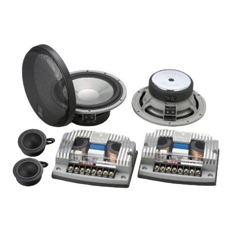
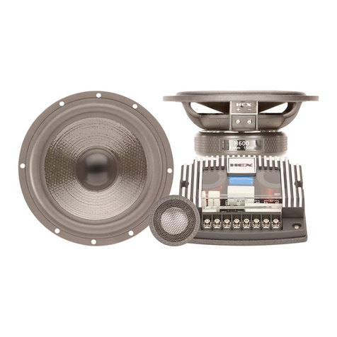
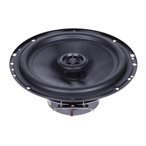
Diamond Audio Technology CM341 User manual

LIMITED WARRANTY STATEMENT
Diamond Audio Technology, Inc. (DAT) warrants all DAT products to be
free of defects in material and workmanship for a period of one (1)
year from the date of original purchase provided they are purchased
from an authorized DAT retailer in the United States. However, the
effective warranty period will be three (3) years if the products were
purchased from and installed by an authorized DAT retailer.
What is covered: Parts and labor to effect repair or, at the sole discre-
tion of DAT, replacement of either any malfunctioning or defective
part(s) or the entire system should the system or any component part(s)
thereof fail to perform as designed. Includes return freight via ground
transportation to destinations within the United States.
What is NOT covered: Installation or setup and repair or replacement of
the system or any parts thereof which, in DAT’s judgment, fail or
become damaged as a result of negligence, improper use, abuse, unau-
thorized modification or service, improper or inadequate packaging
during shipment, installation by a non-authorized dealer, accident, or
use for any purpose other than those for which this product was origi-
nally intended, or where the model’s serial number has been removed,
altered or defaced.
Who is covered: Original purchaser so long as they reside in the United
States and can provide proof of the original date of purchase (e.g.,
store receipt) from an authorized DAT retailer.
OUTSIDE THE UNITED STATES: Customers outside the United States
should contact their local sales office to obtain information on prices,
exchange unit availability, instructions, service and warranty/non-war-
ranty repairs.
Repair or replacement under this warranty is the exclusive remedy of
the consumer. DAT shall not be liable for any incidental or consequen-
tial damages for breach of any expressed or implied warranty on this
product. Except to the extent prohibited by applicable law, any implied
warranty of merchantability or fitness for a particular purpose on this
product is limited in duration to the duration of this warranty. Some
states do not allow the exclusion or limitation of incidental or conse-
quential damages, or allow limitations on how long an implied warran-
ty lasts, so the above limitations or exclusions may not apply to you.
This warranty gives you specific legal rights and you may also have
other rights that may vary from state to state.
HOW TO OBTAIN WARRANTY SERVICE
In the event a DAT product should require servicing, you should (a) visit
an authorized DAT retailer or (b) call the DAT Service Dept. at (866) 328
2834. To be eligible for warranty service within a three (3) year period,
the accompanying receipt of original purchase from an authorized DAT
retailer must specifically note that dealer installation was provided.
Product returned for repair/service must be properly packaged and
clearly marked with the Return Authorization (RA) number issued by
DAT. If the RA number is not clearly marked on the package or no RA
number was issued by DAT, the product may be refused upon delivery.
DAT does not assume responsibility for lost or misdirected product.
Head Office
410 South Benson Lane
Chandler, AZ 85224
Tel: 480-813-6200
Fax: 480-813-6210
Service Department
410 South Benson Lane
Chandler, AZ 85224
Tel: 480-813-6200
Fax: 480-813-6210
Service/Tech Support
Toll Free 1-866-328-2834
www.diamondaudio.com
Passion Drives
the Soul
Rev 052004 © 2004 Diamond Audio Technology, Inc.
All rights Reserved. Features and specifications subject to change without prior notice.


CM3 SERIES
CM3 SERIES
OWNER'S MANUAL
OWNER'S MANUAL
CONVERTIBLE SPEAKER SYSTEMS
CM341 - CM341m
CM351 - CM351m
CM361 - CM361m

Parameter
Parameter
(unit)
Sensitivity (2.83 V @ 1 M) (dB)
Qts
Fs (Hz)
Vas (L)
Rdc (ohm)
Xmax (mm/N)
Impedance (ohm)
Power (rms) (Watt)
CM341/m
CM341/m
88.6
0.48
70
3.7
3.1
2.7
4
60
CM351/m
CM351/m
89.4
0.48
60
8.6
3.3
4.8
4
100
CM361/m
CM361/m
90.6
0.49
51
18.9
3.6
6.2
4
120
CM3 CONVERTIBLE SPEAKER SYSTEMS
Features
-Textured, High Mineral Content Copolymer Cones
-Aluminum Dome Tweeters with Ferrofluid Cooling
-High Density Composite Frames
-EPDM Rubber Surrounds
-Flat Progressive Spiders
-Intercooled Motor Design
-Aluminum Voice Coil Former
-Coaxial/Component Convertible Design
-Detachable Onboard Crossovers
-Flush Mount or Coaxial Tweeter Mounting
-Protective Rubber Magnet Cover
Thiele/Small Parameters

Package Contents
-(2) Mid Bass Speakers
-(2) Mid Bass Speaker Grills
-(2) Mid Bass Speaker Gaskets
-(16) Mid Bass Mounting Screws
-(16) Speaker Mounting Screw Clips
-(2) Passive Crossovers (mounted on mid range speakers)
-(2) Crossover to Mid Range Mounting Screws
-(2) Separate Crossover Mounting Zip Ties
-(2) Crossover to Mid Bass Speaker Wire (component set up)
-(4) Spare Crossover Terminal Screws
-(2) Bridge Mount Tweeter Cups
-(8) Bridge Mounting Countersink Screws
-(2) 1” Aluminum Dome Tweeters (mounted in bridge)
-(2) Tweeter Bridge Cup Mounting Screws
-(2) Tweeter Flush Mount Cups
-(2) Tweeter Flush Mount Kits
-(2) Tweeter Flush Mount Screws
-(2) Tweeter Flush Mount Springs
-(2) Crossover to Tweeter Speaker Wire (component set up)
-(8) Female Wire Connectors (4 wide/4 narrow)
Tweeter Bridge Disassembly/Assembly
1. Remove tweeter bridge mounting screw from back of bridge cup.
2. Slide wire terminals apart so that tweeter leads hang freely.
3. Using a screw driver, gently pop tweeter out of cup through the screw
hole on the back of the cup.
1. To re-assemble, feed tweeter leads through the holes in the cup taking
note of polarity. (red dot indicates positive side)
2. Snap tweeter into cup by aligning the notches on the tweeter and cup.
(do not push on the center of the tweeter grill)
3. Gently tighten the tweeter bidge mounting screw into the tweeter
through the back of the cup. (do not over tighten)
4. Slide wire terminals together tacking in place for added security.
(Disconnect)
(Connect)
Terminal ConnectionsBridge Disassembly/Assembly

Bridge Mounting
1. Remove grill from mid bass speak-
er.
2. Align bridge over mid bass cone
so that the narrow end of the
bridge makes connection with the
points over the terminal side of
the mid bass speaker.
3. Mount bridge to the mid bass
frame using the provided counter-
sink bridge mounting screws. (do
not over tighten)
4. Replacing the grill is optional.
Mid Bass Speaker Mounting
1. Remove grill from mid bass if not already done.
2. Attach provided mid bass speaker gasket to the rear mounting surface
of the frame to ensure proper seal.
3. Mount in desired location using the provided mounting screws. Be cer-
tain to mount the speaker on a flat surface to avoid twisting the frame.
4. Some locations will require pre-drilled mounting holes and screw holes.
Use the provided mounting screw clips in these cases.
5. Follow the wiring instructions detailed later in this manual to finish
installation. (some wiring may need to be done before permanately
mounting the speaker)
6. Replacing the grill is optional.

Flush Tweeter Mounting
1. Remove tweeter from bridge follow-
ing bridge disassembly instructions.
2. Cut a 1.625” diameter hole in desired
location. (make sure it is a flat sur-
face)
3. Insert Flush mount cup screw through
center hole in flush mount cup.
4. Twist flush mount cup spring onto
screw.
5. Push entire assembly through hole cut
earlier and tighten flush mount screw
till cup is held firmly in place by the spring.
6. “Snake” tweeter leads through the wire holes in the cup.
7. Snap tweeter into cup by aligning the notches on the tweeter with the
tabs in the cup. (do not push on the center of tweeter grill)
8. Attach provided tweeter speaker wire to tweeter leads taking note of
polarity. (wire w/ white stripe is positive)
Coaxial Wiring
1. Mount bridge to mid bass following
the bridge mounting instructions.
1. Connect speaker wire from source to
terminals on crossover (already
mounted on speaker) and play.
Tweeter
Mounting
Cup
Spring
Clip
Screw
(align tab and slot)
Crossover Detachment
(for remote crossover mounting in component systems)
1. Remove screw located at the bottom of
the crossover.
2. Gently remove crossover by pulling
downward.
3. Mount crossover to wire harness or some
stable location using provided zip tie.
1. To reattach, line up terminal holes on
crossover with terminals on the mid bass
speaker and gentle push upwards.
2. Replace crossover mounting screw and
tighten. (do not over tighten)

Component System Wiring
1. Remove crossover from mid bass using crossover detachment instruc-
tions.
2. Plug provided tweeter wire male terminals into the inside terminal holes
marked “TWT” on the crossover taking note of polarity. (wire w/ white
stripe is positive)
3. Connect the female ends of the tweeter wire to the tweeter leads. (red
lead is positive)
4. Plug provided mid bass wire male terminals into the outside terminal
holes marked “WFR” on the crossover taking note of polarity. (wire with
white stripe is positive)
5. Connect the female ends of the mid bass wire to the outside terminals
on the mid range, also marked “WFR”. (take note of polarity)
6. Mount the crossovers using the provided zip ties to a secure location
through the center hole in crossover module.
7. Connect speaker wire from source to terminals on crossover and play.
CM361
(OUTPUT)
(INPUT)
+-
+-
TWT WFRTWTWFR
Mid Range
Tweeter
Crossover
(close up of crossover inputs)

112
4.41
4.20
.17
2
8.90
1.14
101.45
3.99
72
THIS DIMENSION IS
WITHOUT RUBBER BOOT
2.83
52
2.05
8.94
.35
25.87
1.02
CM341
General dimensions in mm. and [in.]. (not to scale)

28
1.10
80
THIS DIMENSION IS
WITHOUT RUBBER BOOT
3.15
55.91
2.20
123.19
4.85
148.99
5.87
9
.35
25.87
1.02
134
5.28
4.20
.17
CM351
General dimensions in mm. and [in.]. (not to scale)

9.51
.37
21.52
.85
157
6.18
4.20
.17
23.50
.93
171.99
6.77
68
2.68
143.88
5.66
90
THIS DIMENSION IS
WITHOUT RUBBER BOOT
3.54
CM361
General dimensions in mm. and [in.]. (not to scale)
This manual suits for next models
5
Table of contents
Other Diamond Audio Technology Car Speakers manuals

Diamond Audio Technology
Diamond Audio Technology HEX Series User manual

Diamond Audio Technology
Diamond Audio Technology HEX S400 User manual

Diamond Audio Technology
Diamond Audio Technology D652 User manual

Diamond Audio Technology
Diamond Audio Technology VSP4BMW User manual

Diamond Audio Technology
Diamond Audio Technology Motorsport M245i User manual

Diamond Audio Technology
Diamond Audio Technology M541 User manual

Diamond Audio Technology
Diamond Audio Technology MOTORSPORT M5 Series User manual

Diamond Audio Technology
Diamond Audio Technology M541 User manual

Diamond Audio Technology
Diamond Audio Technology D6 Series Quick start guide