DIAMOND DRYERS DIAMOND PLUS GWHD22 User manual

DIAMOND PLUS

TECHNICAL SPECIFICATIONS
IMPORTANT SAFETY INSTRUCTIONS
WARNING – TO REDUCE THE RISK OF FIRE, ELECTRIC SHOCK, OR INJURY TO
PERSONS OBSERVE THE FOLLOWING:
•
Use this unit only in the manner intended by the manufacturer. The manufacturer is not responsible for
any damages caused by misuse or defective installation.
The instructions contained within the installation Template must be followed carefully when installing
this unit. Failure to accurately follow the instructions may result in the incorrect operation of this unit,
damage to property and/or personal injury.
Installation work and electrical wiring must be done by qualified person(s) in accordance with all
applicable codes and standards, including fire-rated construction.
When cutting or drilling into wall or ceiling, do not damage electrical wiring and other hidden utilities.
This unit must be powered by a dedicated circuit branch protected by a circuit breaker with the
appropriate rating. Circuit cable must be fit current consumption for this unit.
This unit has been designed for indoor use only, protect from water, sun and extreme temperatures, do
not install it outdoors or close to moisture and heat generators.
This unit can only be revised, maintained, repaired and removed by qualified person(s).
If the unit stops and works strangely, contact your regional dealer or contractor.
This appliance can be used by children aged from 8 years and above and persons with reduced physical,
sensory or mental capabilities or lack of experience and knowledge if they have been given supervision
or instruction concerning use of the appliance in a safe way and understand the hazards involved. Do not
allow children to play with the appliance or carry out cleaning and user maintenance on this hand dryer.
If the supply cord is damaged, it must be replaced by the manufacturer, its service agent or similarly
qualified persons in order to avoid a hazard.
•
•
•
•
•
•
•
•
⚠
3
EN
Standard mode
Quiet mode
Power 10W
Operating cycle 1 hour on, 1 hour off
Air speed 14m/s
Performance DateItem Category
Drying Time 10 ~ 12 sec
Drip Proof
Isolation
Unit Size
IPX3
CLASS I
H 272mm x W 136mm x D 123mm
Sensor Type Auto Infrared touch free operation
Sensor Range 45° 10~20cm
Timing Protection 50 seconds auto shut off
Standby Power ≤0.5 W
Air Speed (sensing max)96 m/s
Motor Type Brushless DC Motor, 30,000 RPM
Operating Voltage
Power
AC 220~240 V, 50 Hz / AC 110~120, 60Hz
320 W (Heater off)/ 720 W (Heater on)
Q mode 'ON' , 130 W(Heater off) / 530 W (Heater on)
Sterlilization mode
220~240 V
110~120 V 320 W (Heater off)/ 820 W (Heater on)
220~240 V
110~120 V
Q mode 'ON' , 130 W(Heater off) / 630 W (Heater on)
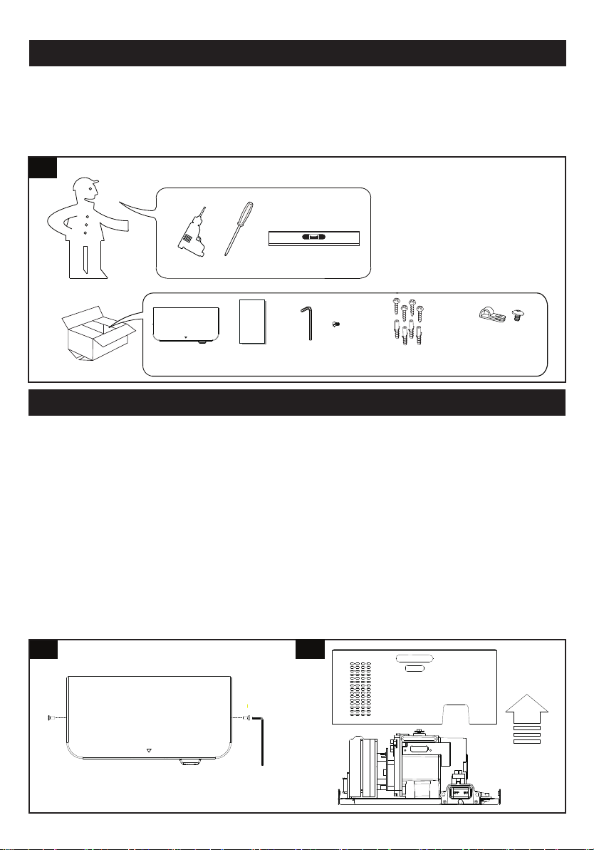
UNPACKING
1. Remove all packing material. Recycling is recommended.
2. Carefully remove the hand dryer from the shipping carton, using care not to drop the appliance.
3.
Inspect carefully for any damage that may have occurred during transit. Check for any loose, missing or
damaged parts. If the hand dryer is damaged, promptly inform the shipper or dealer where you purchased it.
Standard items with the hand dryer are shown in Fig.1 together with tools need by the installer.
1
INSTALLATION
EN
4
EN
CAUTION
•Make sure power supply breaker is switched off.
•
Check that the electrical supply corresponds to that shown on the rating plate. If the unit is connected to
any electrical supply other than stated on the rating plate of the unit, permanent damage or unsafe
operation of the unit may result.
The unit must be mounted on a flat vertical wall capable of supporting the full weight of the unit.
•
•
All electrical installation and repair work should be carried out by a qualified electrician or local service
Engineer in accordance with current local codes or regulations.
1.1 Place the main cover on a cloth to avoid marking its surface.
1.2 Remove the (2) security screws from the main body, using the service tool provided (fig 2).
Store safely.
1.3 Lift the front cover off the main body (fig 3).
1. Remove the Fornt cover
23
Service Tool
& Spare Screw
Installation
template Wall mounting
anchors with screws
Flat cable clamp
& Screw
-in case without
built in power cable
Unit

4
•
2.1 Mark the location on the wall with a pencil. Use the Installation Template to mark the locations for the
four fixing points (fig. 4).
Adult male 1300mm
Adult female 1265mm
Children 5-8 years old 928mm
Children 8-11 years old 1028mm
Children 11-14 years old 1108mm
Wheelchair user 1050mm
Recommended height measurements form the
floor to top screws
Installation target Height
2.2 Pre-drill the wall in the marked locations using 5/16” (8mm) drill, insert the plastic anchors and
tap flush to the wall. If the cable entry is to be done from the wall provide a proper cable exit (fig. 5)
8
5
5
EN
2. Positioning
CAUTION:
Before installation decide if the cable entry is to be from the rear or the above.
Follow the relevant instructions. Do not use the backplate as a guide when drilling.
101.00mm
244.00mm
2.3 Remove the filter kit(shown as Filter replacing step on page 7&8 ).
2.4 Fix the backplate to the wall. Screw to the wall and secure with the appropriate fitting (fig 6).
filter
6
2.5 Replace the filter kit(shown as Filter replacing step on page )
4. ATTACHING MIAN BODY
4.1 Place the main cover of the backplate (fig. 7).
4.2 Insert and tighten the (2) security screws into the side of the main body with the service tool (fig. 8)
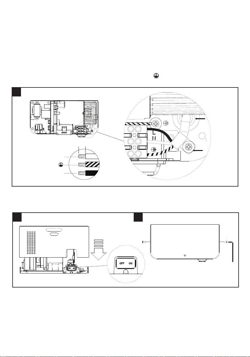
3. Installing Power cable & Connection terminal block
WARNING: ENSURE POWER NOT CONNECTED
3.1 Pull the cable through the the grommet. Ensure the cable is long enough to route correctly through the
backplate to the terminal block (fig 6).
3.2 The cable must sit in the dedicated channel.
3.3 As shown, connect cable to terminal block and screw in terminal block.
3.4 Fix the cable clamp with screw in the backplate (fig 6A).
(In case without built in power cable)
6
CAUTION: Connect the ground wire to the terminal block marked “ ”
Do not over-tighten and crush the power cable.
6
EN
L
N
6mm
Grommet
(cable entry)
Cable clamp
(In case without
built in power cable)
4.2 Give power to the electrical system.
4.3 Check the power switch on (factory default setting “ON”).
4.4 Test the unit for correct operation. The LED light on the cover should flash 5 times with a red light after
the power supply has been correctly connected and followed by continuous light white LED.
7 8
Table of contents
Other DIAMOND DRYERS Dryer manuals

Popular Dryer manuals by other brands


ffuuss
ffuuss eos user manual

KitchenAid
KitchenAid 53-3498 installation instructions

Schulthess
Schulthess Spirit topLine TW 8340 operating instructions

Whirlpool
Whirlpool LGR4624BW0 parts list

World Dryer
World Dryer AirMax D M5-972A manual

Alliance Laundry Systems
Alliance Laundry Systems ADEE9BSS user guide


