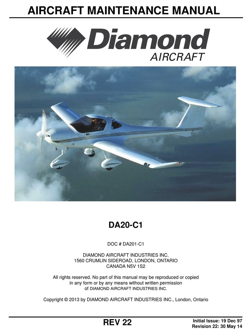
Diamond DA20-C1 User manual

REV 21
AIRCRAFT MAINTENANCE MANUAL
Initial Issue: 19 Dec 97
Revision 21: 14 Jan 13
DA20-C1
Part III (Chapters 51 to 92)
DOC # DA201-C1
DIAMOND AIRCRAFT INDUSTRIES INC.
1560 CRUMLIN SIDEROAD, LONDON, ONTARIO
CANADA N5V 1S2
All rights reserved. No part of this manual may be reproduced or copied
in any form or by any means without written permission
of DIAMOND AIRCRAFT INDUSTRIES INC.
Copyright © 2012 by DIAMOND AIRCRAFT INDUSTRIES INC., London, Ontario

AIRCRAFT MAINTENANCE
MANUAL
DA201-C1
Rev 21
14 Jan 13
This manual contains the maintenance information
required by JAR-VLA. Contents and revision status
can be found in the TABLE OF CONTENTS and the
RECORD OF REVISIONS.
DIAMOND AIRCRAFT INDUSTRIES INC.
1560 CRUMLIN SIDEROAD
London, Ontario, Canada N5V 1S2
http://www.diamondair.com/
For more information contact:
DIAMOND AIRCRAFT INDUSTRIES INC.
Technical Publications
+1-519-457-4030 Ext.3173

Page 1
Rev 16 51-TITLE
Standard Practices - Structures
DA20-C1 AMM
DA201-C1 30 Oct 09
CHAPTER 51-00
STANDARD PRACTICES
STRUCTURES

Standard Practices - Structures DA20-C1 AMM
51-TITLE
30 Oct 09
Page 2 DA201-C1
Rev 16
Intentionally Left Blank

51-TOC
Standard Practices - Structures
DA20-C1 AMM
Rev 21
DA201-C1 Page 1
14 Jan 13
TABLE OF CONTENTS
Subject CH-SE-SU Page
STANDARD PRACTICES - STRUCTURES . . . . . . . . . . . . . . . . . . . . . . . . . . . . . . . 51-00-00. . . . . . . .1
General. . . . . . . . . . . . . . . . . . . . . . . . . . . . . . . . . . . . . . . . . . . . . . . . . . . . . . . . . . . . . . . . . . . . . . . . .1
Structural Classification . . . . . . . . . . . . . . . . . . . . . . . . . . . . . . . . . . . . . . . . . . . . . . . . . . . . . . . . . . . .1
Design, Dimensions, Clearances and Wear Limits . . . . . . . . . . . . . . . . . . . . . . . . . . . . . . . . . . . . . . .3
The Description and Location of Parts . . . . . . . . . . . . . . . . . . . . . . . . . . . . . . . . . . . . . . . . . . . . . . . . .3
Repair Limitations. . . . . . . . . . . . . . . . . . . . . . . . . . . . . . . . . . . . . . . . . . . . . . . . . . . . . . . . . . . . . . . . .3
Inspection Techniques . . . . . . . . . . . . . . . . . . . . . . . . . . . . . . . . . . . . . . . . . . . . . . . . . . . . . . . . . . . . .5
Approved Materials and Suppliers . . . . . . . . . . . . . . . . . . . . . . . . . . . . . . . . . . . . . . . . . . . . . . . . . . . .7
Resin Handling. . . . . . . . . . . . . . . . . . . . . . . . . . . . . . . . . . . . . . . . . . . . . . . . . . . . . . . . . . . . . . . . . . .9
Resin to Hardner Mixture . . . . . . . . . . . . . . . . . . . . . . . . . . . . . . . . . . . . . . . . . . . . . . . . . . . . . . . . . .10
Bonding of Fiber Reinforced Plastics . . . . . . . . . . . . . . . . . . . . . . . . . . . . . . . . . . . . . . . . . . . . . . . . .11
Curing. . . . . . . . . . . . . . . . . . . . . . . . . . . . . . . . . . . . . . . . . . . . . . . . . . . . . . . . . . . . . . . . . . . . . . . . .12
CONTROL SURFACE BALANCING . . . . . . . . . . . . . . . . . . . . . . . . . . . . . . . . . . . . . 51-60-00. . . . . . . .1
General. . . . . . . . . . . . . . . . . . . . . . . . . . . . . . . . . . . . . . . . . . . . . . . . . . . . . . . . . . . . . . . . . . . . . . . . .1
Control Surface Balance. . . . . . . . . . . . . . . . . . . . . . . . . . . . . . . . . . . . . . . . . . . . . . . . . . . . . . . . . . . .1

51-TOC
DA20-C1 AMM
Standard Practices - Structures
14 Jan 13
Page 2 DA201-C1
Rev 21
Intentionally Left Blank

Page 1
Rev 21 51-00-00
Standard Practices - Structures
DA20-C1 AMM
DA201-C1 14 Jan 13
STANDARD PRACTICES - STRUCTURES
1. General
This chapter describes only the basic data about the structure.
The DA20-C1 aircraft is a single-engine, low-wing monoplane of composite construction. It has a 'T' tail.
It also has a fixed tricycle landing gear with a nose wheel that can caster.
The fuselage has a glass fiber skin of semi-monocoque construction with bulkheads and stiffeners.
The tapered cantilever wing has an I-spar. The spar caps are carbon fiber rovings. The wing skin is a
sandwich of Glass Fiber Reinforced Plastic (GFRP) with a rigid foam core. Each wing attaches to the
fuselage at three places.
The vertical stabilizer is part of the fuselage structure. It has a spar near the rudder hinge line and a full
laminate skin. The horizontal stabilizer, elevator and rudder have GFRP skins with rigid foam cores.
The ailerons and flaps have GFRP/CFRP skins with rigid foam cores.
The acrylic canopy has a frame made from carbon fiber laminate.
An epoxy filler with a polyurethane paint protects the aircraft against moisture and ultraviolet rays.
2. Structural Classification
When you do a repair, you must identify the area of the structure (Refer to Figures 1, 2, and 3). If the
damage is larger than the permitted repair, you must ask the manufacturer for advice.
A. Limited Area 1
In this area repairs are permitted on external skin damage up to 250 mm (10 in) in diameter.
B. Limited Area 2
In this area repairs are permitted on external skin damage up to 50 mm (2 in) in diameter.
C. Prohibited Repair Area
Only the manufacturer (or an approved repair facility) can do repairs in this area.
Standard Practices - Structures DA20-C1 AMM
14 Jan 13
Page 2 DA201-C1
Rev 21
51-00-00
Figure 1 - Fuselage Restricted Area Diagram
A
A
B
B
SectionA-A
Prohibited
Limited2
400
200
150
100300
350
300
500
300
150
150
80
400
LIMITEDAREA1
Repairsallowedonexternal
skin damageupto 250mm
(10in)diameter
LIMITEDAREA2
Repairsallowedonexternal
skin damageupto50mm
(2in)diameter
PROHIBITEDREPAIRAREA
Repairstobecarriedoutonly by
themanufactureroranapproved
repair facility
NOTE:All dimensionsaremm
SectionB-B

Page 3
Rev 21 51-00-00
Standard Practices - Structures
DA20-C1 AMM
DA201-C1 14 Jan 13
3. Design, Dimensions, Clearances and Wear Limits
A. Design Dimensions
The detail drawing for the part shows the design dimensions. Use the design dimensions when
manufacturing new parts or for a reconditioning scheme.
B. Clearances and Wear Limits
Where a chapter gives wear limits, the following data is listed:
- The maximum and minimum design dimensions for each part
- The acceptable worn dimensions
- The design assembly and acceptable worn clearances
- The description and location of parts to be examined or inspected
- A remarks column containing recommendations and, where necessary, repair details.
4. The Description and Location of Parts
The Aircraft Maintenance Manual (AMM) gives the description and location of parts. Where a special
repair needs more data, it is shown on the repair drawing.
5. Repair Limitations
You cannot do in-service repairs on these components:
- The main spar and the spar bridge
- Damage close to the main attachment fittings for the wing or horizontal stabilizer.
These are major repairs. You must ask the manufacturer for a repair scheme.
Figures 1 and 2 are the Restricted Area Diagrams. They show where you can do external skin repairs.

Standard Practices - Structures DA20-C1 AMM
14 Jan 13
Page 4 DA201-C1
Rev 21
51-00-00
Figure 2 - Diagram Fuselage Bottom Skin Restricted Area Diagram
LIMITED AREA 1
Repairs allowed on external
skin damage up to 250mm
(10 in) diameter
LIMITED AREA 2
Repairs allowed on external
skin damage up to 50mm
(2 in) diameter
PROHIBITED REPAIR AREA
Repairs to be carried out only by
the manufacturer or an approved
repair facility
NOTE: All dimensions are mm
245
285
100
150
300300
100
70
150
150
150
VIEW LOOKING DOWN ON
BOTTOM SKIN OF FUSELAGE

Page 5
Rev 21 51-00-00
Standard Practices - Structures
DA20-C1 AMM
DA201-C1 14 Jan 13
6. Inspection Techniques
There are different methods of inspecting a damaged composite area. The following gives the
procedures for inspecting a damaged Fiber Reinforced Plastic (FRP) area.
A. Examine Visually
Look carefully at the outer surface of an area or component. If the paint has cracks or bubbles,
then the composite may be damaged. Surface damage, e.g. dents or scratches may be detected
by visual inspection. Look especially in the areas where stones can hit the aircraft below the
fuselage and wings. By visual inspection, you can see where fiber breakage or matrix cracking has
happened. Damage to the core may also be visible.
A bright light can be used to visually examine the inside of a component. GFRP must be green or
brown. If the GFRP has white areas, then it may be damaged. Look especially at areas where
components bond to the GFRP.
Carbon Fiber Reinforced Plastic (CFRP) must be black or black/brown. If the CFRP has white
areas, then it may be damaged. Look especially at areas where components bond to the CFRP.
B. Light Test
A light test can be used to find delamination on components which do not have rigid foam inside.
CAUTION: DO NOT LET THE COMPOSITE GET HOT. HEAT CAN CAUSE DAMAGE TO
THE COMPOSITE.
Point a bright light at the surface of the composite and look at the other side of the surface.
Damage shows as a dark area. You can point the light from the inside or from the outside of a
component.
NOTE: You can use the light test on thick GFRP but it is difficult to use on CFRP.
C. Coin Tap Test
Damage to the laminate can be detected by tapping a coin on the laminate. The sound of tapping
will change its frequency as you move over the damaged area in relation to the sound of other
areas of corresponding thickness. By performing a tap test, you can detect disbonds (the
separation of one component which is bonded to another component) and delaminations (the
separation of individual layers of the glass cloth).
Pay special attention to the area surrounding the damage, because there could be secondary
damage, which can remain undetected.

Standard Practices - Structures DA20-C1 AMM
14 Jan 13
Page 6 DA201-C1
Rev 21
51-00-00
Figure 3 - Wing, Top Fuselage and Horizontal Stabilizer Restricted Area
100
40
100
100100
400400
500
600
500
200200
200200
3030 00
300300
400400
MassBalance
AreaonAileron
150
250
LIMITEDAREA1
Repairsallowedonexternal
skin damageupto250mm
(10in)diameter
LIMITEDAREA2
Repairsallowedonexternal
skin damageupto 50mm
(2in)diameter
PROHIBITEDREPAIR AREA
Repairstobecarriedoutonly by
themanufactureroranapproved
repair facility
NOTE:All dimensionsaremm
NOTE:THEWINGDATAISVALID
FORTOPANDBOTTOMSHELLS

Page 7
Rev 21 51-00-00
Standard Practices - Structures
DA20-C1 AMM
DA201-C1 14 Jan 13
7. Approved Materials and Suppliers
A. Resin and Hardner
Supplier: Scheufler, D-70327 Stuttgart
Resin: L160 (100 parts by weight) Hardener: 163 (28 parts by weight)
Resin: L285 (100 parts by weight) Hardener: 286 (40 parts by weight)
NOTE: L285/286 resin shall be used for DA20-C1S/N C0186 to S/N C0199.
L160/163 resin shall be used for DA20-C1up to S/N C0185 and S/N C0200 and higher.
B. Glass Fiber Cloth
Supplier: Interglas Textil Gmbh
Interglas Technologies AG
BenzstraBe 14. D-89155 Erbach, Germany
C. Carbon Fiber Cloth
Supplier: Interglas Textil Gmbh C.Cramer & Co
Interglas Technologies AG Postfach 1163 48613 Heek Nienborg
BenzstraBe 14. D-89155 Erbach, Germany Weberstrabe 21 Germany
Cloth Mass per Area
grams/m2Interglass No.
Double Twil 2/2 161 92110
Double Twil 2/2 276 92125
Double Twil 2/2 390 92140
Warp reinforced 220 92145
Warp reinforced 433 92146
All cloth is made from alkali free E glass with Volan A Finish or Finish I 550, and complies with
LN 9169.
Cloth Mass per Area
grams/m2P/N
Double Twil 2/2 200 Interglass 98141
Cramer 452T

Standard Practices - Structures DA20-C1 AMM
14 Jan 13
Page 8 DA201-C1
Rev 21
51-00-00
Approved Materials and Suppliers (Continued)
Product Part Number/Description Manufacturer Supplier
PVC Rigid Foam H060 Divinycell Divinycell
Aerosil Aerosil 200 3M
Stochem
106 Summerlea Road
Brampton, ON, L6T 4X3,
Canada
Microbaloons K20 3M Ashland Chemical Canada
10515 Rue Notre-Dame
Motreal, PQ H1B 2V1
Cotton Flocks Quarry Hill
Foundry
Quarry Hill Foundry Supplies
1262 Mcdougall Street
Windsor, ON N8X 3M7
Epoxy Primer
Primer EP669 White
BASF
Hardener PA897
Reducerspeed dependant
on Application Climate
Primer/Surfacer
(High Build)
Primer DP20 BASF
Hardener PH60
Exterior Topcoat
UNO
S/N C0001 to
C0383
Paint HS82004
(Olympia White)
BASFHardener DH46
Reducerspeed dependant
on Application Climate
Exterior Topcoat
AF400
S/N C0384 and up
Paint 752891EP
(Diamond White)
IMRONHardener DH46
Reducerspeed dependant
on Application Climate
Interior Topcoat
UNO-HD
Beige #1501A
BASF
Hardener DH46
Reducerspeed dependant
on Application Climate

Page 9
Rev 21 51-00-00
Standard Practices - Structures
DA20-C1 AMM
DA201-C1 14 Jan 13
8. Resin Handling
A. Introduction
The following steps establish the procedure for preparing resin.
B. Materials
Use only the epoxy resin systems and adhesives, which have been approved for the fabrication or
repair of the aircraft. The approved list of materials and their sources are shown in paragraph 7.
NOTE: L285/286 resin shall be used for DA20-C1S/N C0186 to S/N C0199.
L160/163 resin shall be used for DA20-C1up to S/N C0185 and S/N C0200 and higher.
Interior Texture
Material Paint 1109-1240/4 Glasurit
Instrument Panel
Flat Black
UNO-HD
Paint SC80
BASF
Hardener DH46
Reducer type dependant
on Application Climate
Fire Retardant
Paint
Paint N56582/T508
PPG Aerospace
PRC-Desoto International
Hein-Sass-Weg 29
D-21129 Hamburg-
Finkenwerder
Clear Coat 432-0303
Hardener N39/1327
(use for clear coat only)
Desothane HS Buffable
Clear Coat 9008B900D
Hardner 9008B
Desothane HS Matt Clear
Coat CA8720M0900C
Hardner CA8000B
Interior Baggage
Compartment
Speckled Paint
Multispec
Color MS86-3076
Nightspots
Multicolor
Specialties
Multicolor Specialties
2101 South 54th Avenue
Cicero, IL 60804-2209
Matt Black UNO SC804 BASF
Bonding Material TEROSTAT M9380 TEROSTAT
Product Part Number/Description Manufacturer Supplier

Standard Practices - Structures DA20-C1 AMM
14 Jan 13
Page 10 DA201-C1
Rev 21
51-00-00
C. Procedure
(1) Weigh the cut cloths and determine by ratio the resulting mixed resin weight. The ratio for
glass fiber cloth to resin is: 100:70 and the ratio for carbon fiber cloth to resin is: 100:85.
(2) Dispense only as much resin and hardener as you are able to use within the "working life" of
the resin, at the measured ambient temperature in accordance with the mixture table on
paragraph 9. A very common average mass is 100 g resin per pot. The dispensing error for
the mixing ratio should not be more than 0.5 percent.
(3) Mix the components thoroughly for several minutes. Always scrape the stirring utensil
surfaces as well as the sides of the mixing container, to ensure mixing of all components.
(4) Always thoroughly mix the resin system components before adding fillers or other additives.
(5) Note that small batches tend to have greater dispensing and mixing errors than larger
batches. Therefore, even more care is required when mixing small batches.
(6) Avoid dispensing components into different containers prior to mixing. Best accuracy is
obtained by weighing the resin and the hardener into a single mixing pot. Dispensing by
weight tends to be more precise than dispensing by volume.
(7) Large batches of mixed resin should be poured into flat containers, so that the surface area to
volume ratio is increased. This will reduce the risk of an exothermic reaction.
(8) Note that the resin on the rollers, brushes and other tools will also "cure". For this reason,
clean the tools regularly when lamination is continuing for an extended period of time. Use
only new brushes.
(9) Do not permit resin to become contaminated with foreign substances, other than the specified
additives. Solvents and thinners used to clean the equipment should be dried off before
commencing work with the tools.
WARNING: Curing of resin / hardener mix happens by an exothermic reaction. Therefore,
leftover resin may overheat and is a potential fire hazard. it may cause injury to
personnel.
9. Resin to Hardner Mixture
Scheufler L160/H163 (100:28 weight) Scheufler L285/H286 (100:40 weight)
Resin L160 g Hardner H163 g Resin L285 g Hardner H286 g
50 14 50 20
75 21 75 30
100 28 100 40
125 35 125 50
150 42 150 60
175 49 175 70
200 56 200 80

Page 11
Rev 21 51-00-00
Standard Practices - Structures
DA20-C1 AMM
DA201-C1 14 Jan 13
10. Bonding of Fiber Reinforced Plastics
A. Introduction
The following steps establish the procedure for the bonding of precured fiber reinforced plastic
parts.
B. Materials
Resin
Resin Filler/Thickner
(1) Scotchlite K20 (.19g/cc) Microballoons 3M
(2) AerosilFillerStochem
(3) Cotton flocksCotton fibersQuarray Hill
C. Procedure
Preparation of Bonding Paste
Bonding pastes are used primarily for adhesive bonding of precured fiberglass parts. Bonding
paste or thickened resin is a mixture of three types of fillers and mixed resins.
Refer to the table below.
The following combination of thickening fillers shall be used for preparation of bonding paste:
microballoons + aerosil: maximum 7% by weight
Cotton Fibers: minimum 7% by weight
Quantity of microballoons and aerosil may be varied to change paste consistency.
The total mix of fillers must not exceed 20% by volume.
Refer to the table below for the recommended mixture.
Joining of Precured Parts
Material Weight in Grams
Mixed Resin 50 100 150 200 250 300 350 400 450
CottonFlocks 5 1015202530354045
Aerosil 1.5 3 4.5 6 7.5 9 10.5 12 13.5
Microballoons 24681012141618

Standard Practices - Structures DA20-C1 AMM
14 Jan 13
Page 12 DA201-C1
Rev 21
51-00-00
(1) Pre-fit the parts to be bonded to make sure that there is adequate clearance and mark out the
exact bonding area between the parts as necessary for paste application. Note the gap
between the parts.
(2) Disassemble the pre-fitted parts and prepare the surface for bonding by removing the peel-ply
or abrading the surface.
(3) Prepare resin.
(4) Prepare bonding paste.
(5) Wet all the bonding surfaces with a thin coat of mixed resin (not thickened).
(6) Apply the bonding paste with a putty knife or a piping bag. Apply bonding paste to a depth
appropriate with the bond gap, as determined by the trial fit. Avoid trapping air by contouring
the paste higher in the middle of the joint.
(7) Fit the parts and remove excess bonding paste as it is squeezed out.
(8) Immobilize the parts until the pre-cure is complete (approximately 24 hours at 20°C, 68°F).
(9) Do not disturb the bonded parts until the full pre-cured duration has been reached.
11. Curing
A. Introduction
The following steps establish the procedure for curing a composite repair.
B. Material
Curing oven or a temporary enclosure with a heat source.
C. Procedure
(1) Precuring
Temperature: 20 - 25 oC (68 - 77 oF)
Time: 24 hours
(2) Postcuring
Temperature: 60 oC ± 5 oC (140 oF)
Time: 15 hours
The post cure may be divided into sections, as long as the total time at the required temperature
is at least 15 hours.
(3) If you do not have an oven or a warming room, construct a temporary enclosure around the
repair area to entrap heat.

Page 13
Rev 21 51-00-00
Standard Practices - Structures
DA20-C1 AMM
DA201-C1 14 Jan 13
(4) Use a heat source with variable heat control to apply heat to the ambient air around the repair
area. Do not point the heat gun directly at the composite material. Ensure that the nozzle of
the heat gun is more than 12 inches away from the area being cured. Use a thermocouple
probe to measure the surface temperature at the repair. Adjust the heat source to maintain
60 oC ± 5 oC (140 oF).
(5) Measure and record the temperature every 15 minutes for the first hour and then every hour
after that.
(6) It is not recommended to leave the repair unattended during the post cure, due to the risk of
overheating or fire.

Standard Practices - Structures DA20-C1 AMM
51-00-00
14 Jan 13
Page 14 DA201-C1
Rev 21
Intentionally Left Blank
Other manuals for DA20-C1
4
Table of contents
Other Diamond Aircraft manuals

Diamond
Diamond DA40 NG User manual

Diamond
Diamond DA20-C1 User manual

Diamond
Diamond DA20-C1 User manual

Diamond
Diamond DA 40 Technical specifications

Diamond
Diamond DA40 NG User manual

Diamond
Diamond DA 62 Technical specifications

Diamond
Diamond JAR-VLA Technical specifications

Diamond
Diamond DA20-C1 Technical specifications

Diamond
Diamond DA20-C1 Manual

Diamond
Diamond DA 42 Technical specifications