DIAsource ImmunoAssays ELISA PLATE SHAKER User manual


U
Us
se
er
r
M
Ma
an
nu
ua
al
l
E
EL
LI
IS
SA
A
P
PL
LA
AT
TE
E
S
SH
HA
AK
KE
ER
R
-
-
I
IN
NC
CU
UB
BA
AT
TO
OR
R
Version 201217 Page 2 of 26
TABLE OF CONTENTS
1. GENERAL INFORMATION...................................................................................................................4
1.1. WARRANTY INFORMATION:.....................................................................................................................4
1.2. TECHNICAL SERVICE:..............................................................................................................................4
1.3. DISPOSAL INSTRUCTION:.........................................................................................................................4
1.4. CONTACTS:...........................................................................................................................................5
2. GENERAL SAFETY WARNINGS ..........................................................................................................6
2.1. DANGER –WARNINGS SYMBOLS:...............................................................................................................6
2.2.USE OF THE INSTRUMENT:......................................................................................................................7
3. INTRODUCTION ..................................................................................................................................8
3.1. SPECIAL FEATURES:...............................................................................................................................8
3.2. SPECIFICATIONS:....................................................................................................................................8
4. PACKING, TRANSPORT AND STORAGE............................................................................................9
4.1. GENERAL WARNINGS:.............................................................................................................................9
4.2. PACKING:..............................................................................................................................................9
4.3. INSTRUMENT TRANSPORTATION:.............................................................................................................9
4.4. STORAGE OF THE INSTRUMENT:...............................................................................................................9
5. INSTRUMENT DESCRIPTION ............................................................................................................10
5.1. PERSPECTIVE VIEW:.............................................................................................................................10
(A) FRONT VIEW .........................................................................................................................................10
(B) REAR VIEW............................................................................................................................................10
6. INSTALLATION PROCEDURE AND VERIFICATION CRITERIA ........................................................11
6.1. UNPACKING INSTRUCTIONS:..................................................................................................................11
6.2. PLACING THE INSTRUMENT:..................................................................................................................11
6.3. POWER SUPPLY REQUIREMENTS:............................................................................................................11
6.4. PROTECTIVE GROUNDING:....................................................................................................................11
6.5. START UP INSTRUCTIONS:.....................................................................................................................11
7. PRECAUTIONS ..................................................................................................................................12
8. GENERAL KEY AND OPERATION.....................................................................................................13
8.1. KEYPAD:...........................................................................................................................................13
8.1.1. START / YES KEY ......................................................................................................................... 13
8.1.2. STOP / NO KEY............................................................................................................................ 13
8.1.3. SHAKE KEY .................................................................................................................................. 14
8.1.4. FUNC KEY:................................................................................................................................... 15
8.1.5. MENU KEY: ................................................................................................................................. 16
8.1.6. TIMER KEY:. ................................................................................................................................ 17
8.1.7. CLEAR KEY .................................................................................................................................. 18
8.1.8. TEMP KEY ................................................................................................................................... 19
8.1.9. ENTER KEY .................................................................................................................................. 19
8.2. DEFAULT SETTING (OPERATING MODE)..................................................................................19
9. SAVING THE TEST ............................................................................................................................20
10. DELETING THE TEST .....................................................................................................................21
11. RECALLING THE TEST ...................................................................................................................22
12. ERROR MESSAGES..........................................................................................................................23
13. DECONTAMINATION ......................................................................................................................24
13.1. DECONTAMINATION PROCEDURE:........................................................................................................24

U
Us
se
er
r
M
Ma
an
nu
ua
al
l
E
EL
LI
IS
SA
A
P
PL
LA
AT
TE
E
S
SH
HA
AK
KE
ER
R
-
-
I
IN
NC
CU
UB
BA
AT
TO
OR
R
Version 201217 Page 3 of 26
13.2. PURPOSE OF DECONTAMINATION:........................................................................................................24
13.3. GENERAL CONSIDERATIONS:...............................................................................................................24
13.4. DECONTAMINATION PROCEDURE:........................................................................................................24
14. SAFETY CLEARANCE CERTIFICATE: ............................................................................................25
15. SPARE PARTS .................................................................................................................................26
15.1. ORDERING SPARE PARTS:...................................................................................................................26

U
Us
se
er
r
M
Ma
an
nu
ua
al
l
E
EL
LI
IS
SA
A
P
PL
LA
AT
TE
E
S
SH
HA
AK
KE
ER
R
-
-
I
IN
NC
CU
UB
BA
AT
TO
OR
R
Version 201217 Page 4 of 26
1. GENERAL INFORMATION
1.1. Warranty Information:
Each Instrument is completely tested and guaranteed for twelve months from
delivery. The warranty applies to all the mechanical and electrical parts. It is
valid only for proper installation, use, and maintenance in compliance with the
instructions given in this manual.
DIAsource ImmunoAssays S.A. will at its discretion repair or replace parts,
which may be found defective in the warranty period. The warranty does not
include any responsibility for direct or indirect personal and/or material
damages, caused by improper use or maintenance of the instrument.
Parts that are inherently subject to deterioration are excluded from the
warranty. In case of defects due to misuse of the instrument, any incidental
expenses like travel and man-hour service charges will be charged extra.
1.2. Technical Service:
DIAsource ImmunoAssays S.A. is always accessible to the customers for any
kind of information about installation, use, maintenance, etc. While asking for
service, please refer to this manual, and report the printed serial no. on the
identification label.
Only qualified technicians are entitled to fix the instrument; the user, as
described in this manual, should carry out ordinary maintenance.
1.3. Disposal instruction:
In case of removal or disposal of instrument, following instructions need to be
followed
•Do not dispose in municipal waste; follow local regulations for
instrument disposal.
•Plastic parts, Electronic PCBs and components can be recycled, so return
back the instrument to manufacturer.

U
Us
se
er
r
M
Ma
an
nu
ua
al
l
E
EL
LI
IS
SA
A
P
PL
LA
AT
TE
E
S
SH
HA
AK
KE
ER
R
-
-
I
IN
NC
CU
UB
BA
AT
TO
OR
R
Version 201217 Page 5 of 26
1.4. Contacts:
DIAsource ImmunoAssays S.A.
Rue du Bosquet 2
BE-1348 Louvain-La-Neuve
BELGIUM
IVD Instrumentation Support Service
Hotline phones availabilities : Monday to Friday; 08 :30 to 17:00 (Belgium time)
Please contact first Hotline 1. In case of no response please contact Hotline 2.
Hotline 1 phone number : 0032 (0)10 849932
Hotline 2 phone number : 0032 (0)10 849976
Fax : 0032 (0)10 849990
U
Us
se
er
r
M
Ma
an
nu
ua
al
l
E
EL
LI
IS
SA
A
P
PL
LA
AT
TE
E
S
SH
HA
AK
KE
ER
R
-
-
I
IN
NC
CU
UB
BA
AT
TO
OR
R
Version 201217 Page 6 of 26
2. GENERAL SAFETY WARNINGS
2.1. Danger –warnings symbols:
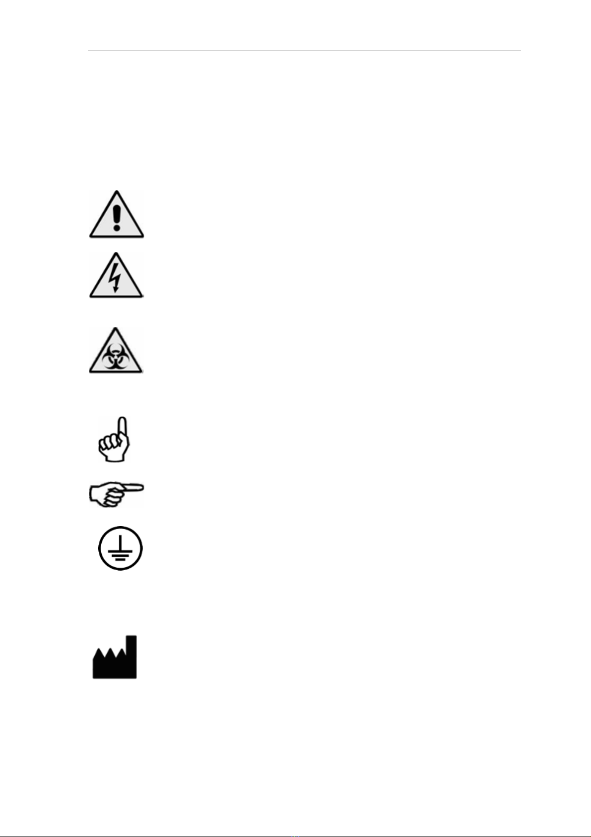
The following symbols are used to inform the user of the safety rules.
This symbol indicates generic danger. It means that, serious
damage can occur to the operator if described precautions are
not observed.
This symbol indicates HIGH ELECTRIC VOLTAGE. It is dangerous
to touch any part having this label. Only qualified operators can
access these components, after unplugging the instrument from
the Supply.
This symbol indicates that the instrument involves the handling
of samples, which can be infected (urine or human serum). In
this condition, infection or contamination might occur. Pay
attention to the general safety warnings when in presence of
such biological substances. Use Protective clothes, gloves and
glasses.
This symbol in the user manual indicates that damages to the
instrument or erroneous results could occur if the given
warnings are not followed.
This symbol indicates a portion, which is particularly important,
and should be studied carefully.
This symbol indicates a Protective Earth or Ground terminal.
General Symbols
Symbol for “Manufacturer”

U
Us
se
er
r
M
Ma
an
nu
ua
al
l
E
EL
LI
IS
SA
A
P
PL
LA
AT
TE
E
S
SH
HA
AK
KE
ER
R
-
-
I
IN
NC
CU
UB
BA
AT
TO
OR
R
Version 201217 Page 7 of 26
2.2. Use of the Instrument:
The instrument has to be used for the designed purposes under specified
conditions, following proper procedures and safety rules, by qualified
personnel.
THIS MANUAL CONTAINS INSTRUCTIONS FOR OPERATION BY QUALIFIED
PERSONNEL ONLY.
➢A qualified user has to make sure that the environmental condition is
suitable, the installation is correct, the use and maintenance are proper,
according to the general safety rules as well as to the particular
precautions described in the manual (However, the user is not entitled
to repair the instrument).
➢A qualified technician is entitled to maintain and fix the instrument,
according to the instructions given, using the original spare parts.
➢Maintain room temperature and humidity as specified in the manual.
➢The instrument must be used as described in this manual only. Usage in
any other way will be regarded as improper.
➢Alterations to the instrument are strictly prohibited. The user is liable
and solely responsible for any improper modification to the instrument,
and for the consequences derived as a result.

U
Us
se
er
r
M
Ma
an
nu
ua
al
l
E
EL
LI
IS
SA
A
P
PL
LA
AT
TE
E
S
SH
HA
AK
KE
ER
R
-
-
I
IN
NC
CU
UB
BA
AT
TO
OR
R
Version 201217 Page 8 of 26
3. INTRODUCTION
3.1. Special Features:
Simultaneous shaking & incubation operation.
Buzzer indication on completion of incubation
Indication of Remaining time
Current temperature of incubation on display, on pressing TEMP Key.
Separate Timer ON indication on Keypad.
3.2. Specifications:
Operating Modes
Shaker
Incubator
Shaking & Incubator
Temperature Control
Temperature Range
Resolution
370 C to 420 C
10 C
Incubation Time
1 to 999 min
Shaker
Frequency
Amplitude
400 to 700 RPM
2 mm
Operating Position
On horizontal flat, rigid and vibration
free surface
Operating Conditions
Temperature
Relative Humidity
From + 180 C to 320 C
Up to 80%
Storage Conditions
Temperature
Relative Humidity
From -100 C to 350 C
Up to 80%
Enclosure
ABS Fire retardant
Size (cm)
28 X 25 X 16 (l X b X h)
Weight
3 Kgs (Approx)

U
Us
se
er
r
M
Ma
an
nu
ua
al
l
E
EL
LI
IS
SA
A
P
PL
LA
AT
TE
E
S
SH
HA
AK
KE
ER
R
-
-
I
IN
NC
CU
UB
BA
AT
TO
OR
R
Version 201217 Page 9 of 26
4. PACKING, TRANSPORT AND STORAGE
4.1. General warnings:
Instrument has to be decontaminated before packing for transportation.
4.2. Packing:
Packaging is needed whenever it is to be transported or shipped by
courier or other means.
To pack the instrument follow the instructions as below described:
oDecontaminate the instrument as explained in
chapter No. 13 (Decontamination) of this manual.
oPlace the instrument into the original packaging box;
Instrument has to be properly protected by plastic protective
material. Put copy of safety clearance certificate (copy of Safety
Clearance certificate is attached at the end of this manual)
oMark the package with address, instrument
identification and warning Labels.
4.3. Instrument Transportation:
The transportation of the instrument in unpacked condition must be
limited within the room where it is used, to avoid damage.
4.4. Storage of the Instrument:
Before storing the instrument for a long period, pack it carefully as
described above and store indoors.
Relative humidity can be up to 80%, and temperature between -10ºc
and 35ºc.

U
Us
se
er
r
M
Ma
an
nu
ua
al
l
E
EL
LI
IS
SA
A
P
PL
LA
AT
TE
E
S
SH
HA
AK
KE
ER
R
-
-
I
IN
NC
CU
UB
BA
AT
TO
OR
R
Version 201217 Page 10 of 26
5. INSTRUMENT DESCRIPTION
Components of different views of the below pictured instrument:
5.1. Perspective View:
(A) Front View
(B) Rear View
Input power socket
On/Off switch
Cooling Fan
Incubator / Shaker Plate
holder
Numeric
Keypad
Display

U
Us
se
er
r
M
Ma
an
nu
ua
al
l
E
EL
LI
IS
SA
A
P
PL
LA
AT
TE
E
S
SH
HA
AK
KE
ER
R
-
-
I
IN
NC
CU
UB
BA
AT
TO
OR
R
Version 201217 Page 11 of 26
6. Installation procedure and verification criteria
6.1. Unpacking instructions:
Check accessories as per packing list.
Kindly store all packing materials so as to use it to repack and
ship for maintenance or servicing.
6.2. Placing the instrument:
-The instrument has to be placed on a level bench.
-Room temperature has to be between 10 and
35ºC with a relative humidity below 85%.
Protect it from direct sunshine
6.3. Power supply requirements:
Once the instrument has been placed, plug it into a power
source by the locally available approved plug-in cable.
Power cord should be CE, CSA, and UL marked.
115 - 230 Volts ± 10V, 60-50 Hz
6.4. Protective Grounding:
Warning : Please make sure that electrical power source is
properly grounded.
6.5. Start up Instructions:
oSwitch on the instrument. The instrument will display the
company name
oThe instrument initializes all the parameters internally, and
carries out a power on self-test. It then displays “company name”.
The temperature control of the plate starts. The temperature of
the plate will maintain at 37 ºC ± 0.5
oThe instrument is now in IDLE mode, and ready for use.

U
Us
se
er
r
M
Ma
an
nu
ua
al
l
E
EL
LI
IS
SA
A
P
PL
LA
AT
TE
E
S
SH
HA
AK
KE
ER
R
-
-
I
IN
NC
CU
UB
BA
AT
TO
OR
R
Version 201217 Page 12 of 26
7. PRECAUTIONS
Precautions:
Keep the place dry and clean.
Check all the grounding wires properly.
Use original packaging for transportation.
U
Us
se
er
r
M
Ma
an
nu
ua
al
l
E
EL
LI
IS
SA
A
P
PL
LA
AT
TE
E
S
SH
HA
AK
KE
ER
R
-
-
I
IN
NC
CU
UB
BA
AT
TO
OR
R
Version 201217 Page 13 of 26
8. GENERAL KEY AND OPERATION
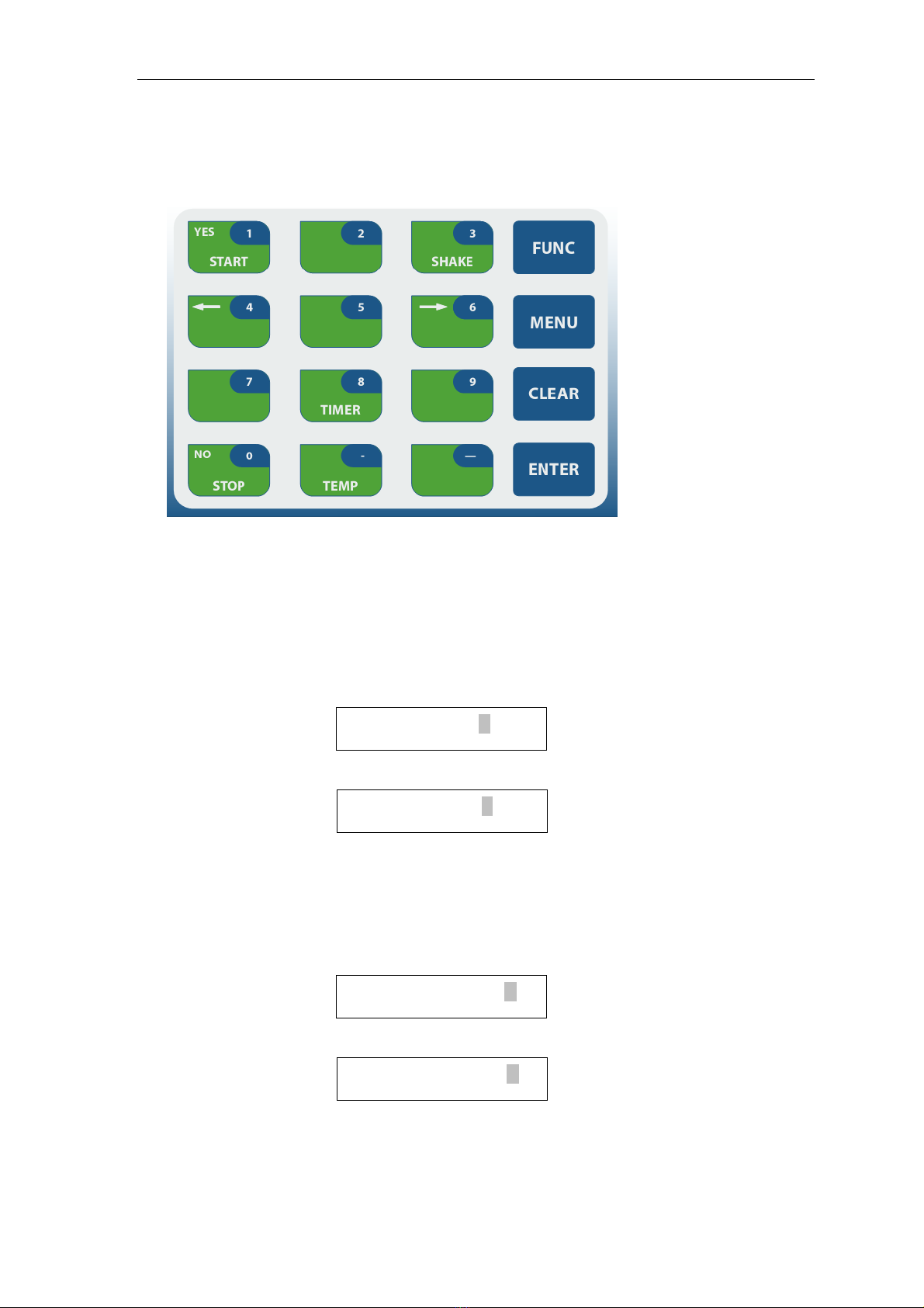
8.1. KEYPAD:
8.1.1. START / YES KEY
This option helps the user to START the process of Shaking.
Similarly, “YES” key is used when the instrument asks certain questions as
follows –
For eg:
OR
8.1.2. STOP / NO KEY
This option helps the user to STOP the process of Shaking.
Whereas, “NO” key is used to answer certain questions such as –
For eg:
OR
In such a case, user must select either “YES” or “NO” options to proceed further.
START SHAKE Y / N ?
CREATE TEST Y / N ?
START SHAKE Y / N ?
CREATE TEST Y / N ?
U
Us
se
er
r
M
Ma
an
nu
ua
al
l
E
EL
LI
IS
SA
A
P
PL
LA
AT
TE
E
S
SH
HA
AK
KE
ER
R
-
-
I
IN
NC
CU
UB
BA
AT
TO
OR
R
Version 201217 Page 14 of 26
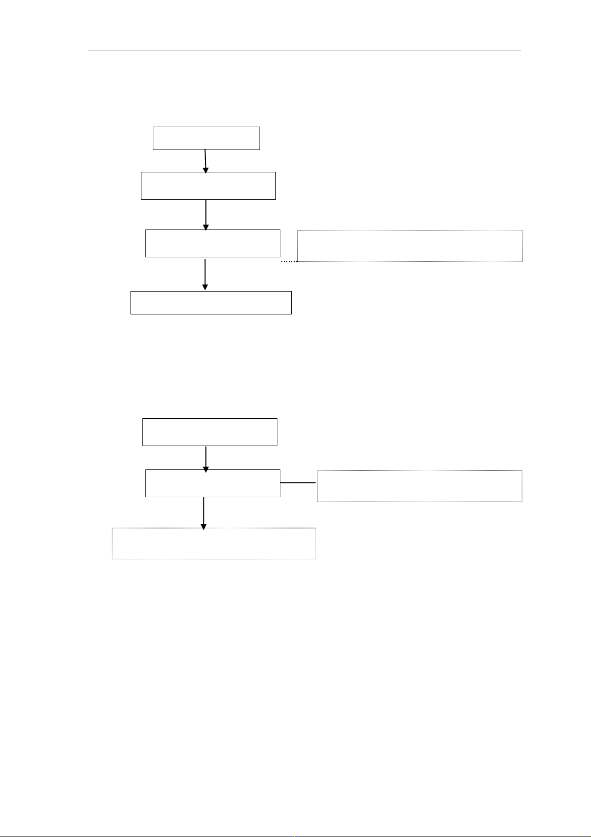
8.1.3. SHAKE KEY
User can directly start the process of Shaking just by selecting “SHAKE” key present on
the keypad.
Finally Shaker starts at 400 RPM. This process continues until user selects STOP
button
present on the keypad.
For Terminating the process, select STOP button.
START SHAKE Y/ N ?
SET RPM = 400
SHAKE
RPM: 400 STOP Y/ N
STOP
YES
Enter the RPM between 400 to 700 and press
Enter key. Its default value is 500 RPM
On selecting “YES” option, it STOPS the
process of Shaking
Select “NO” option, in order to continue the
process of Shaking
YES
NO
PRESS ENTER KEY
U
Us
se
er
r
M
Ma
an
nu
ua
al
l
E
EL
LI
IS
SA
A
P
PL
LA
AT
TE
E
S
SH
HA
AK
KE
ER
R
-
-
I
IN
NC
CU
UB
BA
AT
TO
OR
R
Version 201217 Page 15 of 26
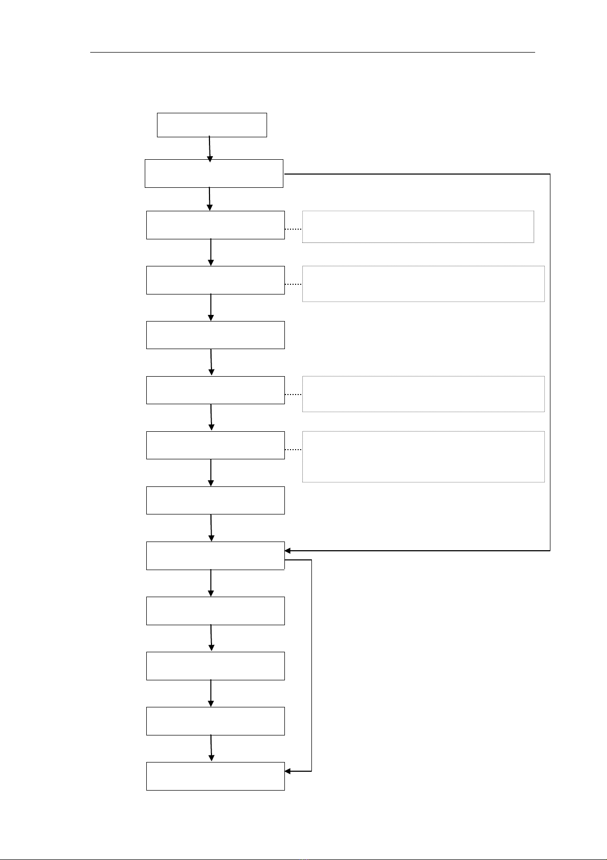
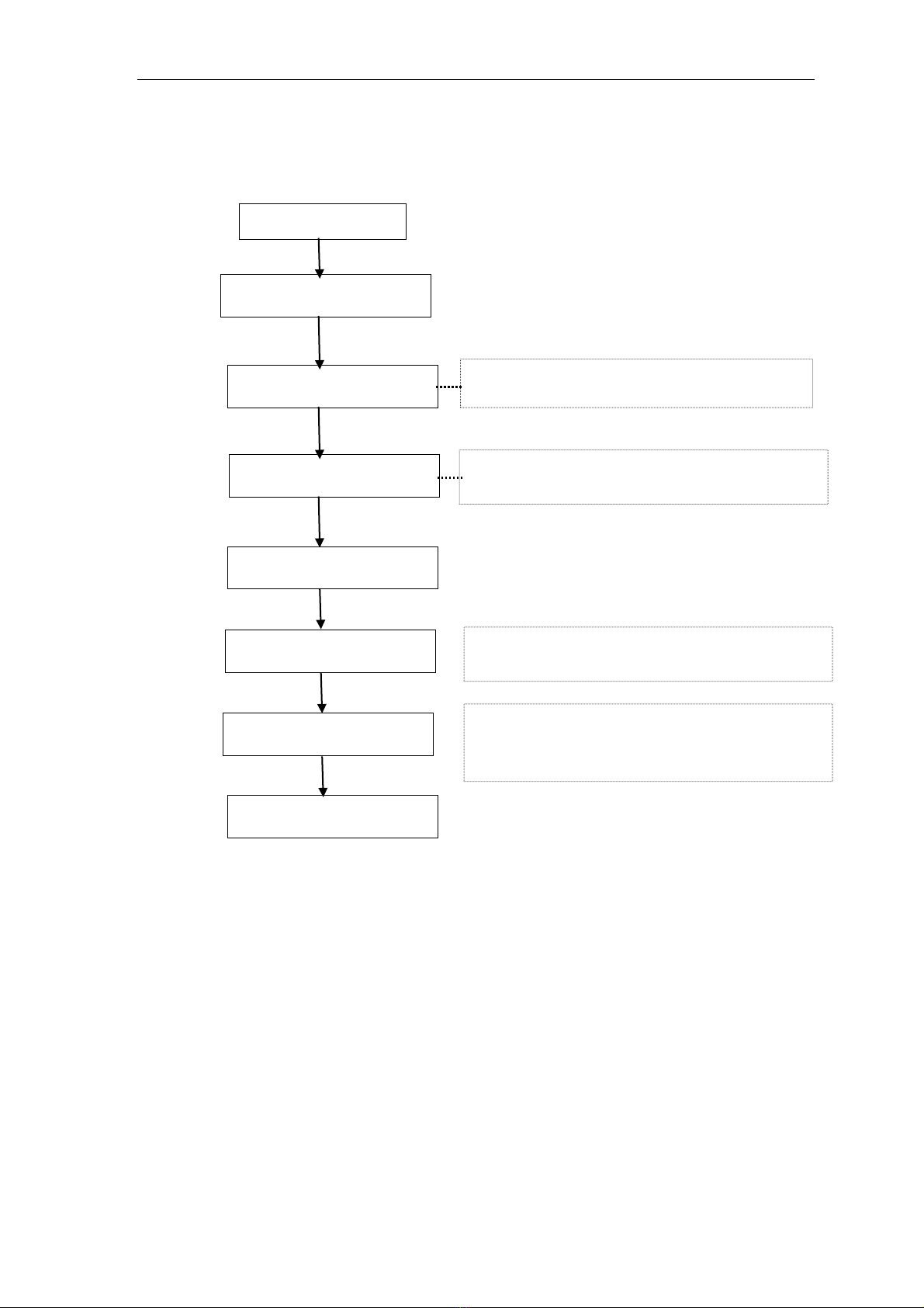
8.1.4. FUNC KEY:
CREATE TEST Y/ N ?
SET RPM = 400
FUNC
SET TIMER 1 = 50
SET TIMER 2 = 70
SET TEMP = 37C
SAVE TEST NO = 5
TEST SAVED
DELETE TEST Y/ N ?
ENTER TEST NO = ___
CONFIRM Y / N ?
TEST DELETED
INITIAL SCREEN
NO
NO
NO
YES
YES
Enter the RPM between 400 to 700 and press
Enter key. Its default value is 500 RPM
Set TIMER1 & TIMER2 between 1 –999 min and
press Enter key. Its default value is 30 min
Set TEMP between 37°C to 42°C and press Enter
key. Whereas, its default value is 370 C.
Enter the Test no. in order to save the test
parameters. Remember user can save maximum
9 tests.
Press FUNC button present on the keypad
YES

U
Us
se
er
r
M
Ma
an
nu
ua
al
l
E
EL
LI
IS
SA
A
P
PL
LA
AT
TE
E
S
SH
HA
AK
KE
ER
R
-
-
I
IN
NC
CU
UB
BA
AT
TO
OR
R
Version 201217 Page 16 of 26
8.1.5. MENU KEY:
This option helps the user to recall the saved test by entering its test no.
Enter the Valid Test No. or else it will display following string-
Since, user can save maximum 9 tests; one has to enter the test no. in between
–9 in order to recall the test.
If user enters the number which donot exist or in other words, the test is not saved
with that particular number; then in such a case it will display following string-
ENTER TEST NO = ___
TEST RECALLED
Enter the Test No. and select ENTER key
TEST NOT EXIST
INVALID TEST NO
MENU

U
Us
se
er
r
M
Ma
an
nu
ua
al
l
E
EL
LI
IS
SA
A
P
PL
LA
AT
TE
E
S
SH
HA
AK
KE
ER
R
-
-
I
IN
NC
CU
UB
BA
AT
TO
OR
R
Version 201217 Page 17 of 26
8.1.6. TIMER KEY: This option is used to set the timer for the respective plates
After selecting Timer1 and Timer2, LED glows of the respective Timer. On completion
LED gets OFF and the buzzer beeps in order to indicate that the Timer has reached its set
value. Now select Enter key to stop the buzzer.
The TIMER continues until user selects STOP button present on the keypad.
For Terminating the process, select STOP button
TIMER 1 Y/ N ?
START TIMER Y/ N ?
TIMER
START TIMER Y/ N
TIMER 2 Y/ N ?
YES
NO
SET TIMER 1 = 30
SET TIMER 2 = 30
Enter TIMER1 between 1 –999 min and press
Enter key. Its default value is 30 min
Enter TIMER2 between 1 –999 min and press
Enter key. Its default value is 30 min
YES
NO
YES
YES
STOP
YES
TIMER 1
TIME : 9 STOP Y/ N
Select “YES” option in order to Stop the
TIMER
S

U
Us
se
er
r
M
Ma
an
nu
ua
al
l
E
EL
LI
IS
SA
A
P
PL
LA
AT
TE
E
S
SH
HA
AK
KE
ER
R
-
-
I
IN
NC
CU
UB
BA
AT
TO
OR
R
Version 201217 Page 18 of 26
8.1.7. CLEAR KEY
This key is used to select the Language option and also to clear the test entry.
In other words, user can abort the test by pressing CLEAR key.
TIMER 2
TIME : 10 STOP Y/ N
Select “NO” option, in order to continue the
TIMER
S
CLEAR
FRENCH LANGUAGE : Y / N ?
Select “Yes” for French Language or otherwise
“No” to continue in English.

U
Us
se
er
r
M
Ma
an
nu
ua
al
l
E
EL
LI
IS
SA
A
P
PL
LA
AT
TE
E
S
SH
HA
AK
KE
ER
R
-
-
I
IN
NC
CU
UB
BA
AT
TO
OR
R
Version 201217 Page 19 of 26
8.1.8. TEMP KEY
NOTE: By Default condition incubator heating is off, Instrument will show Room
Temperature
8.1.9. ENTER KEY
Enter button present on the keypad helps the user to set the value for the selected
parameters
(ie. on completion of data entry)
8.2. DEFAULT SETTING (OPERATING MODE)
PARAMETERS
DEFAULT VALUES
RANGES
RPM
500 RPM
400 to 700 RPM
Temperature range
370 C
370 C to 420 C
Incubation Time
Timer 1
Timer 2
30 min
30 min
1 to 999 min
Set value and press ENTER Key
XX = 37°C to 42°C
Incubator Heating OFF (Room Temperature)
It will set to room temperature
Press TEMP button present on the keypad
TEMP
ROOM TEMP. Y/N ?
37ºC SET TEMP Y/N
SET TEMP = 37ºC
INITIAL SCREEN
YES
YES
NO
NO
U
Us
se
er
r
M
Ma
an
nu
ua
al
l
E
EL
LI
IS
SA
A
P
PL
LA
AT
TE
E
S
SH
HA
AK
KE
ER
R
-
-
I
IN
NC
CU
UB
BA
AT
TO
OR
R
Version 201217 Page 20 of 26
9. SAVING THE TEST
Saving the Test itself means creating new test with new parameters.
CREATE TEST Y/ N ?
SET RPM = 400
FUNC
SET TIMER 1 = 50
SET TIMER 2 = 70
SET TEMP = 37C
SAVE TEST NO = 5
TEST SAVED
YES
Enter the RPM between 400 to 700 and press
Enter key. Its default value is 500 RPM
Set TIMER1 & TIMER2 between 1 –999 min and
press Enter key. Its default value is 30 min
Set TEMP between 37°C to 42°C and press Enter
key. Its default value is 37°C
Enter the Test no. in order to save the test
parameters. Remember user can save maximum
9 tests.
Press FUNC button present on the keypad
This manual suits for next models
1
Table of contents
Languages:
Popular Accessories manuals by other brands

Rinstrum
Rinstrum K404 Reference manual

IFM Electronic
IFM Electronic O1D105 operating instructions

Xiaomi
Xiaomi Aqara quick start guide
352C66 Installation and operating manual")
PCB Piezotronics
PCB Piezotronics PCB-(M)352C66 Installation and operating manual

GLD Products
GLD Products VIPER 777 Replacement parts

Kobold
Kobold OPT Series operating instructions


Plantronics
Plantronics AP-1 ACCESSORY POD quick start guide

Atlona
Atlona OmniStream 238 installation guide

Xcellon
Xcellon PB-1200AC user manual

HEIDENHAIN
HEIDENHAIN TTR ERM 2200 Mounting instructions

Orion
Orion SKYLINE 5673 manual

Dwyer Instruments
Dwyer Instruments MFS Series Installation and operating instructions