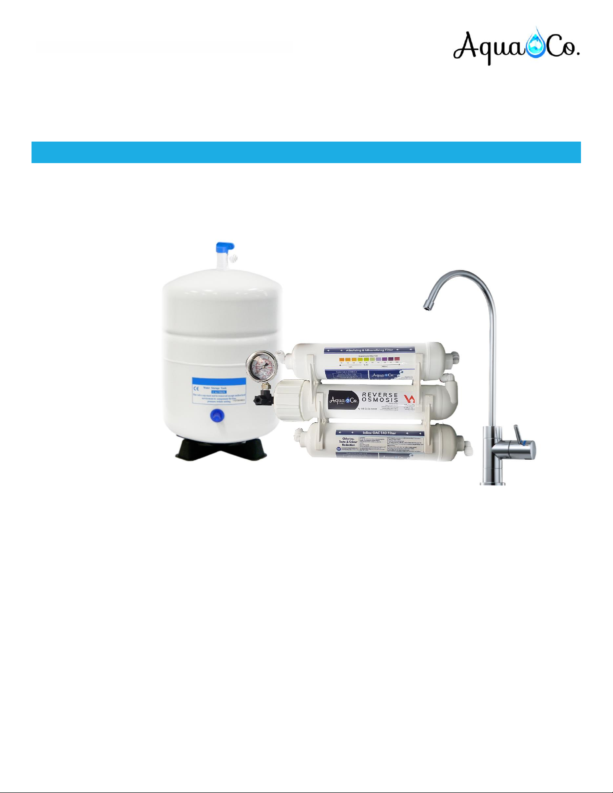
Compact Reverse Osmosis For Whole House Filtration Systems
Product Code: SYS-ROCOMP
Page 7of 17
INSTALLATION PROCEDURE
Important Note: Do not cut the BLACK tube when installing this system.
1. Find a convenient location: The System dimensions are 300W x 200 H x 100 D (mm), and the tank dimensions are 244 D x
366 H (mm). The tank can go laying down as well as the system.
2. Shut Off the water supply: Locate the connection between the kitchen tap & cold-water line (Usually a flex line). Shut off the
incoming water and open the tap (cold water) to release the pressure.
3. Disconnect the cold water braided hose: If you do not know which one is the hot or cold, run the hot water for a while and
feel the hoses.
FEEDING THE SYSTEM WITH HOT WATER, WILL DAMAGE THE SYSTEM
4. Install the mains adaptor: From the cold-water inlet, install the valve adaptor/mains connector in
between. DO NOT apply thread tape to these connections as they are designed to use the
washers only. (Fig 3)
5. Push the red tube all the way in to stop. Connect ¼” RED inlet tube to mains connector.
6. Check for leaks: With the black handle facing in line with the cold-water line (As pictured)
the valve is in the off position. During this point, you can turn the water back on to check
for leaks in the valve installation.
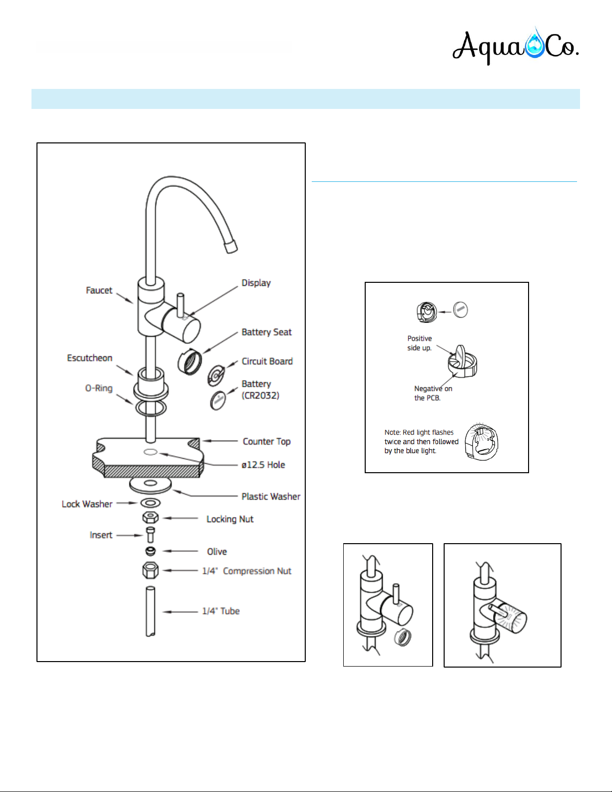
7. Select location on kitchen sink to install faucet. Make sure there is adequate access under
the bench top for the hoses. The faucet supplied with the system requires a ½” (12 mm) hole.
Use a centre punch to locate the position to drill.
8. Drill a pilot hole and gradually enlarge until you have the correct size hole.
9. To install faucet, insert the faucet into the hole in sink or bench. The faucet may be installed on any flat surface over 50mm
(2”) in diameter. (Remember: check the underside of the location for interference). Make a small indent using a centre punch
to mark the desired drilling location. Drill a pilot hole with a metal drill. Enlarge the hole using a 1⁄2” metal drill bit.
Once the hole has been drilled install the faucet as per Figure 4. Be sure the faucet body, chrome plate, and the black rubber
washer are placed above the sink. Install the black locating washer, the lock washer and nut underneath, then tighten firmly
while aligning faucet in the desired direction. Connect BLUE tube to faucet. (Fig 1)
10. Reset LED indicator by following instructions on page 10.
11. Install the drain clamp by drilling a 4 mm hole in the waste pipe. Position the drain
clamp above the trap. Connect ¼” BLACK drain tube to drain clamp and tighten
compression nut. Do not allow drain hose to protrude more than 10 mm into drain,
making sure the holes in the drain and the clamp are exactly aligned. This can be
done by inserting a thin Phillips screwdriver through them whilst tightening the
clamp. (Fig 4)
12. When connecting the red, black, blue and white tubes leave plenty of extra
length so that the purifier can be repositioned during servicing without having to
disconnect all the hoses.
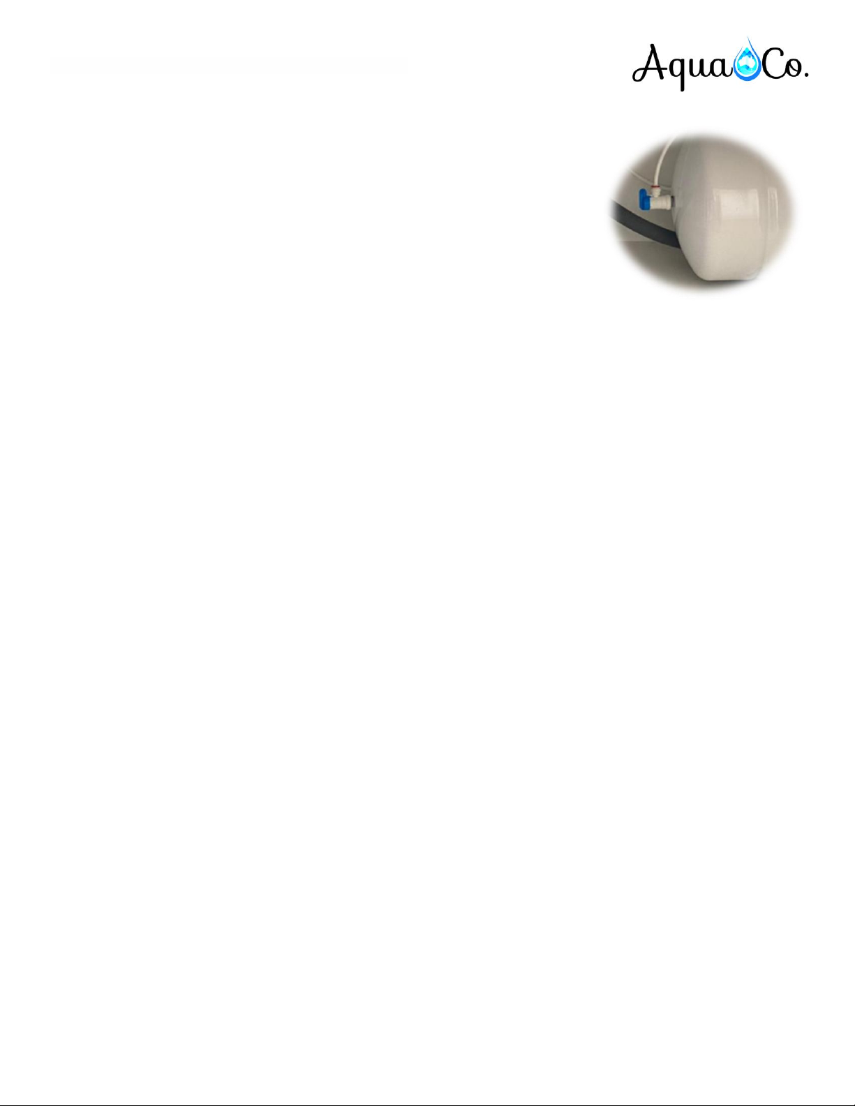
13. Connect WHITE tube to storage tank. Screw ball valve to tank outlet and ensure valve
is open. (Fig 5)