Diatest DIATRON 2200 User manual

DIATRON 2200
Document No. : DT2200/EN/V2
Edition: 03/2011
© Copyright : DIATEST
Hermann Költgen GmbH
Instruction Manual
DIATRON2200
Column Gauge

2
Manual DIATRON 2200
Contents
1. Introduction
1.1 General information......................................................................................................................... 4
1.2 Measuring and display features ...................................................................................................... 4
1.3 Front and rear panel ....................................................................................................................... 5
1.4 Dimensions ..................................................................................................................................... 6
1.5 Hole pattern for interconnection ..................................................................................................... 6
1.6 Technical data ................................................................................................................................ 7
2. Getting started
2.1 Delivered items ............................................................................................................................... 8
2.2 Fitting the base ............................................................................................................................... 8
2.3 Fitting the modules ......................................................................................................................... 8
2.3.1 Removal of DIATRON2200 column cover ................................................................................... 8
2.3.2 Connecting the modules .............................................................................................................. 9
2.3.3 Fitting modules in DIATRON2200 column gauges ...................................................................... 10
2.3.4 Fitting of bus terminator ............................................................................................................... 10
2.3.5 Fitting of DIATRON2200 column cover ........................................................................................ 11
2.4 Measurement input addresses ........................................................................................................ 11
2.5 Connecting several column gauges ................................................................................................ 12
2.6 Power supply connection ................................................................................................................ 13
2.7 Connecting a foot or hand switch .....................................................................................................14
2.8 Connecting adaptors for tolerance outputs ......................................................................................14
2.9 Connecting a PC, multiplexer or statistic printer .............................................................................. 15
2.10 Connection of wireless module ......................................................................................................15
2.11 Connection of probes, air plug gauges, sensors and measuring instruments ................................16
2.12 Modules at a glance .......................................................................................................................18
2.13 Power on / Self-test ........................................................................................................................18
3. Programming the column gauge
3.1 Encoder functions ............................................................................................................................ 19
3.2 Foot and hand switch functions ........................................................................................................19
3.3 Quick programming guide for programmers in a hurry .................................................................... 20
3.4 Description of calibration mode ........................................................................................................21
3.4.1 Zero adjustment / Calibration ........................................................................................................21
3.4.2 Probe set-up ..................................................................................................................................21
3.5 Description of programming mode ...................................................................................................22
3.6 Basic Setup …...................................................................................................................................27
3.7 Restoring factory settings .................................................................................................................31
3.8 Error messages / Error corrections .................................................................................................. 31
3.8.1 Operating and programming errors ...............................................................................................31
3.8.2 System error ................................................................................................................................. 32
4. Working with the column gauge
4.1 Initial start-up ....................................................................................................................................33
4.2 Measurement operation ....................................................................................................................33
4.3 Mechanical setup of inductive probes ............................................................................................. 33
4.4 Automatic zero adjustment of gauges ..............................................................................................34
4.5 Automatic gauge calibration .............................................................................................................34
4.6 Multi gauging ( C1...C8 ) ...............................................................................................……………. 34
5. The RS232 interface
5.1 Transmission format and wiring .......................................................................................................35
5.2 Data format ...................................................................................................................................... 35
5.3 Table of commands ..........................................................................................................................35

3
Manual DIATRON 2200
5.4 Requesting measured values .......................................................................................................... 36
5.5 Transfer of measured data ...............................................................................................................36
5.6 Importing measurement values into Windows applications ............................................................ 36
5.7 Importing measurement values into MS-EXCEL ............................................................................. 36
6. Male connector pin assignments
6.1 Measuring controller connectors ......................................................................................................37
6.2 Termina blocks for accessories ........................................................................................................37
7. Accessosries and order placement information ................................................................................ 39
8. Safety Instructions ..............................................................................................................................40
9. Guarantee ........................................................................................................................................ 41

4
Manual DIATRON 2200
1.
Introduction
1.1 General information
1.2
Measuring and display features
Static measuring mode
Dynamic measuring modes : Min, Max, Tir, Mean
Bore measuring mode with automatic function
Multi-gauging measuring modes :Manual or automatic selection of 1 to 8 gauges
Measuring range / Resolution : ± 3,0 mm / 0.1 µm, 0,12 / 0.00001 inches (inductive probes)
± 30 mm / 1 µm, 1,2 / 0.0001 inches (inductive probes)
24 Bit (incremental measuring systems)
Unit :
mm and inches
2-digit numeric display: Gauge number C1 … C8
Measuring input P1 … P8
Basic setup menu L0 … L9
Numeric display ranges
Relative measurements : ± 9.9999 mm / ±99.999 mm, ±.99999 inches / ±9.9999 inches
Absolute measurements : 0 to 99.9999 mm / 0 to 999.999 mm, 0 to 9.99999 inches / 0 to 99.9999
Inches
Number of grades : 1…30
The DIATRON2200 column gauge is an electronic gauge
for connecting 1 to 4 inductive probes (on request also
other modules are available).
The column gauge allows the manual or automatic selec-
tion of 1 to 4 gauges, including static and dynamic meas-
uring programmes and the optional selection (grading) of
workpieces in up to 30 classes.
Highly sophisticated measuring programmes allow a quick
and simple calibration with 1 or 2 masters.
Two numeric displays allow the output of absolute meas-
ured values, comparative deviations or the classification of
workpieces as well as the corresponding gauge numbers.
The 3-colour column display with superimposable toler-
ance limits gives a fast overview over the tolerance result
of the workpieces and is an ideal tool for quality checks of
workpieces in mass production.
The new Bus system of the DIATRON2200 provides solu-
tions for more sophisticated measuring applications
through the simple interconnection of several column
gauges.

5
Manual DIATRON 2200
Numeric display 6-digit
Programming menu
Rotary encoder
Numeric display 2-digit
Dynamic mode display
Column display ranges
± 5.0000 mm ± 0.50000 ″
The 3-colour column display ( red, green, yellow )
± 1.5000 mm ± 0.15000 ″features an
automatic colour selection according
± 0.5000 mm ± 0.05000 ″to the tolerance limits.
± 0.1500 mm ± 0.01500 ″
A maximum of 4 tolerance limits can be programmed.
± 0.0500 mm ± 0.00500 ″
The tolerance limits are output as coloured marks inside
± 0.0150 mm ± 0.00150 ″
the column display.
± 0.0050 mm ± 0.00050 ″
The column display ranges can be set to AUTO or to a fixed range in the BASIC SETUP menu. In the AUTO mode the
column gauge automatically selects the optimal column display range depending on the given tolerance limits. The selected
column display range is shown in the measuring mode on the numeric display by pressing the Encoder button
for more than 2 seconds. User-defined column display ranges can be programmed with the PC software DT2200_PC.EXE.
1.3
Front and rear panel
RS232 connector
Foot / Hand switch and
tolerance outputs
Power supply
100...240 VAC
Tolerance limits (4)
Measuring module for 1, 2
or 4 inductive probes
3-colour column
Bus terminator

6
Manual DIATRON 2200
1.4 Dimensions
1.5
Picture: Column display with base
Picture: Column display with base

7
Manual DIATRON 2200
1.6 Technical data
Mechanical characteristics
Case
Base plate Aluminium anodised, plastic top and bottom parts
Aluminium powder-coated
Front panel Plexiglass
Control element Rotary encoder with button
(16 detents / rotation)
Dimensions W x H x D / Weight 56 x 418.5 x 86 mm / 1340g ( incl. Base plate
( DIATRON2200 incl. Base plate, power supply and interface
modul= 1650g )
Electrical characteristics
Power supplies
Primary switched power supply 100 to 240VAC, 45 to 60Hz
Max. power consumption 2.5 VA ( without measuring modules )
Display
Numeric display Column display
Scale with 103 and 2 LEDs for “out-of-range” display,
3-colour, with automatic colour selection and
programmable tolerance marks
Numeric display
6-digit and 2-digit LED displays: 7.62 mm, red
LEDs
Mode, Einheit, Programmiermenüanzeigen 17 LEDs, red
Connections
Interface (RS232)
9-pin SUB-D port, hardware: EIA RS232 standard,
data format corresponds to OPTO RS232
2 trigger inputs / tolerance outputs
(Ft 1 / Ft 2) 9-pin SUB-D port
Trigger input for external contacts and serial
output for OC3, OE3 and OP3 adapters
Measurement parameters
Measuring range / Resolution
± 99,9999 mm / 0.1 µm, ± 4,00000 / 0.00001 inches
± 999,999 mm / 1 µm, ± 40,0000 / 0.0001 inches
Resolution Auflösung
16 bits ( analogue ),
24 bits ( incremental measuring systems )
Sampling rate Messrate 50 measurements per second
For measurement error specifications, linearity, hysteresis and temperature drift please refer to the technical
data pertaining to the measuring module in question
Bus
Bus
9-pin SUB-D male (input) / female ( output ),
Hardware: EIA RS485 Half Duplex, automatic addressing,
max. of 64 clients, max. Bus length 1200 m
Environmental condition
Operating temperature range 0 ... 50°C
Storage temperature range -30 ... +60°C
Protection Front panel IP65 ( CEI / IEC 529 )
Rear panel depending on the measuring modules
Electromagnetic compatibility (EMC)
Electromagnetic compatibility ( EMC ) Generation of interference according to EN50081-2
Resistance to interference according to EN50082-2
8
Manual DIATRON 2200
2. Getting started
2.1 Delivered items
Column gauge, base with 4 screws ( M3x8 ) for fixing, instruction manual, programming card, and
a 2.0 mm Allen key.
Further accessories, such as measuring controllers, power supply modules, measurement
modules, foot switches, or adaptors according to shipping order.
Please check the shipment for completeness and keep the packaging.
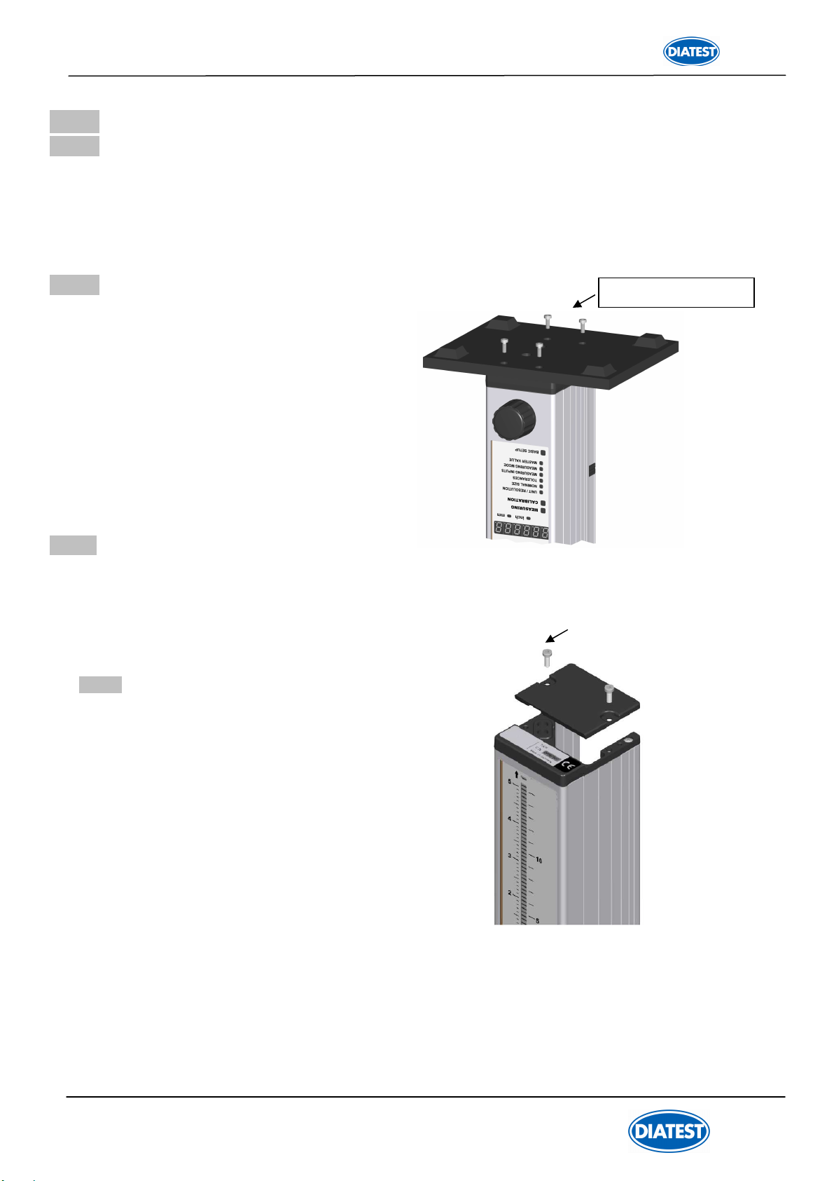
2.2
Fitting the base plate
Use the Allen key ( included in shipment )
to fixate the screws of the base and set
the column gauge on a solid base.
!!! Do not overtighten screws !!!
2.3
Fitting the modules
The DIATRON2200 column gauge has been developed for use in modules and provides for the connection
of 1 to 4 (8) probes. The respective modules of the this series can be fitted to the rear panel of the
DIATRON2200 to connect probes (pls. ask).
2.3.1 Removal of DIATRON2200 column cover
Use the Allen key ( included in
shipment ) to undo and remove both
retaining screws of the column cover.
Then remove the column cover.
4 x DIN 7984 M3 x 8

9
Manual DIATRON 2200
A DIATRON2200 column gauge that comprises modules is configured in a fixed order. If one single
DIATRON2200 is to be configured, the power supply model ( 1 ) always has to be fitted first, followed by
the measuring controller module ( 2 ) and then finally ( starting with no. 3 ) the measuring and interface
modules in no fixed order. The address designation ( Ch.1 to Ch.8 ) of the connected sensors or measur-
ing instruments determines the order. The DIATRON2200 column gauge can read a maximum of 8 con-
nected sensors or measuring instruments.
If several DIATRON2200 are to be connected, the adaptor cable ( 1 ) is to be fitted first, followed by the
power supply module ( 2 ), then the measuring controller and finally the measuring and interface module in
no fixed order.
One power supply module can support up to 3 DIATRON2200 column gauges in this way. If more than 3
DIATRON2200 are interconnected, an additional power supply module has to be fitted for the fourth
DIATRON2200.
Extensions cables can be used at any point between the individual modules, if needed. Sensitive signal
leads from inductive probes, configurations can hence be avoided. The total maximum length of all exten-
sion cables must not exceed 1200 m.
2.3.2 Connecting the modules
(1) Push both red levers of the first module against the stop and rotate to the stop
( set up )
.
(2) Connect modules.
(3) Rotate back both red levers to lock the modules while pressing them together.
Follow steps (1), (2) and (3) to connect the modules one after the other.
The following table indicates the installation sequence of the modules.
Position 1 is the bottom position later on, and is screwed to the base of the DIATRON2200 column
gauge.
!!! Important : The bottom module must be equipped with bolts to do so.
Position Module
1 Connection cable
( only if interconnecting several column gauges )
2
power supply modules
3
measuring controller module
4 measuring and interface modules
Important :
Should an module already be equipped with bolts
( e.g. when using an connection cable )
,
please replace the bolts with 2 cross-recessed screws
( included in shipment )
in order to en-
able connecting of modules.
(1) (2) (3)

10
Manual DIATRON 2200
2.3.3 Fitting modules into the DIATRON2200 column gauge
Once the modules have been connected, they are slid into the DIATRON2200 column section as a
package from the top and are then screwed to the column base using both cross-recessed screws.
!!! Do not overtighten screws !!!
If modules have already been fitted into the DIATRON2200 column and additional modules are to
be installed, then all previously fitted modules must be removed first.
Loosening and removing previously fitted modules :
The modules are screwed to the DIATRON2200 base by means of 2 screws. At first both cross-
recessed screws must be loosened by using a suitable screwdriver in order to remove the fitted
modules. Two lock washers keep the screws in place and they remain in the DIATRON2200
base. The base does not need to be removed. Once both screws have been completely loos-
ened, the modules can be slid to the top of the column and removed from it.
After removal of the initially fitted modules, additional modules
can be added. Afterwards the complete module package can be
slid into the DIATRON2200 column section. Finally the module
package is screwed to the column base.
2.3.4 Fitting of bus terminator
Prior to inserting the modules into the column profile, the bus terminator connector is attached to
the vacant port of the last module and screwed to it.
If the last module has not been fitted with bolts to fix the terminator connector, both cross-recessed
screws will have to be removed and replaced with bolts.
The bolts are included in the shipment !!!
Remove modules
Loosen screws

11
Manual DIATRON 2200
About the bus terminator :
The purpose of the bus terminator is to terminate the bus lines electrically, to seal the open port,
and to provide information on the function and the power supply of the column gauge.
The “VCC” LED lights up when the power supply to the column gauge is secured. The “VCC” LED
will be extinguished, if the power supply module has been overloaded due to external consumers,
such as digital probes with high current consumption, or as a result of voltage drops due to long ex-
tension cables. The design, however, allows adding power supply modules
between any gauging and interface modules at will, to compensate voltage drops.
The “RUN” LED lights up, when the self-test of all modules has finished successfully.
The “RUN” LED will not light up and will thus signal that the could not be completely checked, if
more modules have been fitted than can be addressed by the column gauge.
Note : The “RUN” LED will not issue an error message in this case, but instead signalises the
incomplete self-test of modules that cannot be addressed.
2.3.5 Fitting of DIATRON2200 column cover.
Place the column cover on top of the DIATRON2200
and fix with two Allen screws ( M3 x 8).
!!! Do not overtighten screws !!!
2.4. Measurement input addresses
The measurement inputs are referred to
as Ch.1 to Ch.8 for subsequent programming.
The bottom measurement input is always
Ch.1. It is possible to connect more than 8
measurement inputs, the DIATRON2200 column
gauge, however, can only address and read in
the first 8 inputs.
Note :
When connecting further column gauges via adapter cables,
the measurement inputs ( Ch.1 to Ch.8 )of the first column
gauge are also available at the subsequent column gauges
and are referred to as the same addresses. Therefore, there
is no complex behaviour to pay attention to when program
ming.
When connecting several column gauges, please take
into account the following facts:
A further measuring module in a series of column gauges
will interrupt the connection to the previous measuring
modules, and make available its inputs for the subsequent
column gauges, including the one it is fitted into.
See also example 2 on page 13 of this manual.
Ch. 7
Ch. 6
Ch. 5
Ch. 4
Ch. 3
Ch. 2
Ch. 1
Ch. 8
Bus terminator connector
Measuring
controller
module
Power supply
module

12
Manual DIATRON 2200
2.5 Connecting several column gauges
Adapter cables are utilized to connect several column gauges.
The adapter cables fulfil two tasks :
1.) Transferring the supply voltage from the first column gauge to the next.
One power supply module can supply power to a maximum of 3 column gauges, depending on the connected
probes, sensors and measuring instruments. The number of column gauges decreases, if the current con-
sumption of the connected measuring instruments exceeds 200 mA. As shown in Example 2, power supply
modules can be added at will. Each module performs the function of supplying power up to the next power
supply module
.
2.) The measurement inputs Ch.1 to Ch.8 of the first column gauge are made available for the sub-
sequent column gauges.
The measurement inputs are passed on to the subsequent column gauges via the adapter cables. The data
flow direction within the adapter cable is always from the thinner adapter housing towards the thicker adapter
housing. A further measuring module in a series of column gauges will interrupt the connection to the previous
measuring modules, and make available its inputs for the subsequent column gauges, including the one it is
fitted into. See also example 2 on page 14 of this manual.
Mechanical connection of column gauges : The housing connector underneath the column cover
serves to link together the column gauges. Take the
connector out of its storage and screw it together with
the column cover.
!!! Do not overtighten screws !!!
Example 1 : connecting 3 column gauges
The three-column gauges are linked together via two
adapter cables. The adapter cables are always fitted in
the first position
( bottom
slot )
, whereat the thinner
adapter section is always fitted to the first column
gauge. When using several adapter cables make sure
that the thinner adapter section is fitted in the first posi-
tion, with the thicker adapter section of the arriving ca-
ble directly above it. The power supply module of the
first column gauge supplies all three column gauges
with power. The measurement inputs Ch.1 to Ch.4 are
available at all three column gauges.
13
Manual DIATRON 2200
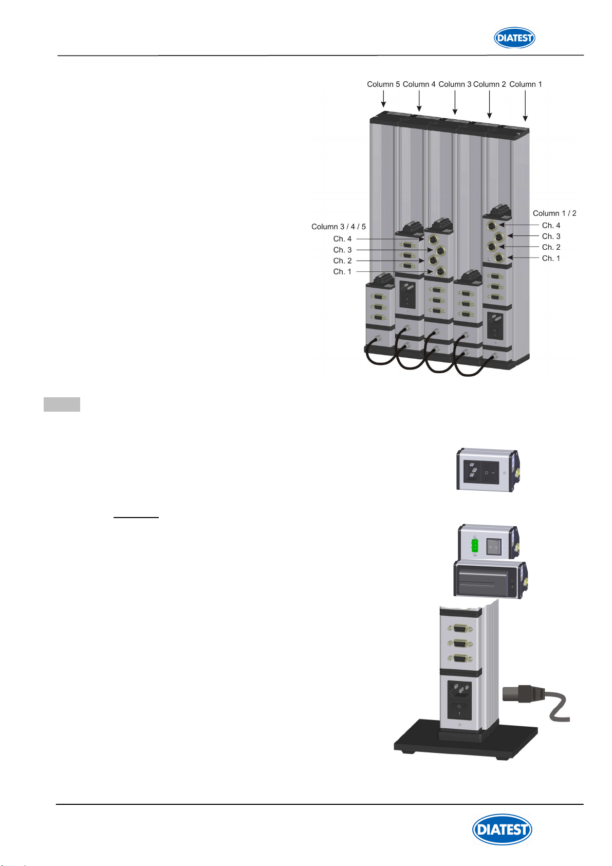
2.6 Power supply connection
There are three modules available to supply the column gauge with power :
1. Standard
Switched-mode power supply featuring wide range
voltage input from 100 to 240 VAC, 45 to 60 Hz
Optional:
2. DC to DC converter for input voltage range from 9 to 32 VDC
3. Rechargeable battery (accu-pack) module for battery-operated systems.
The module allows quick battery replacement. Rechargeable batteries
with capacities of 1850 / 4000 and 5500 mAh are available.
( Example : DIATRON2200 with 2 inductive probes and a 4000 mAh battery
Pack can operate for approx. 12 to 15 hours )
First read the sticker information on the fitted power
supply module and then check whether the module is
suitable for your mains voltage respectively DC voltage.
Use the enclosed power cable to connect the DIATRON2200.
Important !!! Insert device plug into grounded
outlet only
Example 2 : connecting 5 column gauges
The five column gauges are linked together via four
adapter cables. The cables are always fitted in the
bottom positions, as shown
in the illustration. The measurement inputs are
passed on from the thinner adapter section towards
the thicker adapter section. When using several
adapter cables make sure that the thinner adapter
section is fitted in the first position, with the thicker
adapter section of the arriving cable directly
above it. The power supply module of column 1
supplies columns 1, 2 and 3 with power. The power
supply module of column 4 interrupts the further
power supply from column 1 and supplies columns 4
and 5 with power. The measuring module in column
1 makes available the measurement inputs ( Ch.1 to
Ch.4 ) for columns 1 and 2. The measuring module
in column 3 interrupts the connection to the meas-
urement inputs from column 1 and makes available
its own measurement inputs at columns 3, 4 and 5.
14
Manual DIATRON 2200
Ft1
Ft2
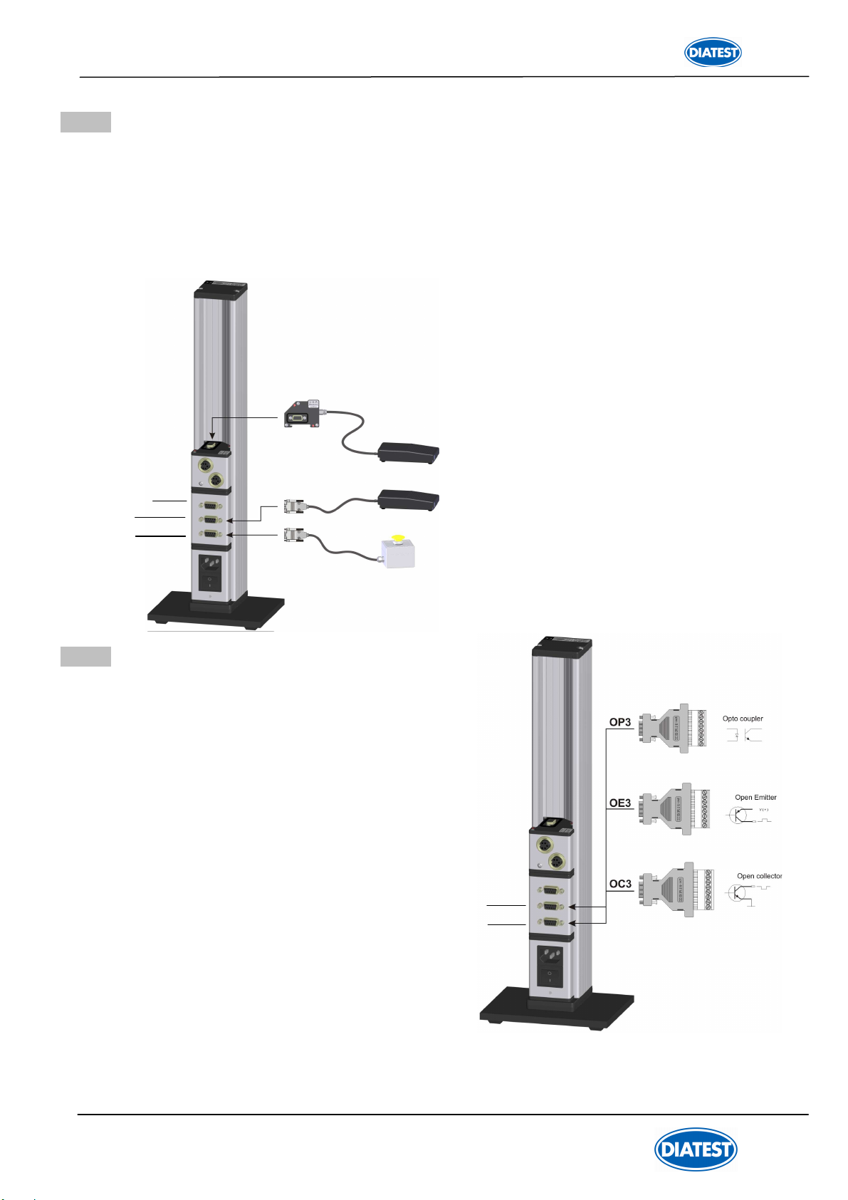
2.7 Connecting a foot or hand switch
The foot or hand switches are connected to the Sub-D ports Ft1 and Ft2 of the measuring controller.
A third switch input is available, if an foot or hand switch is used. The foot or hand switch can
be added at any place behind of the.
The functions of the foot or hand switches can be configured in the “BASIC SETUP”
menu ( L3 -L5 ).
Important !!!
Secure all connections by screwing them tight.
Plug-in connector pin assignments :
see Chapter 6
2.8 Connecting adapters for tolerance outputs
The adapters for the tolerance-controlled
outputs are connected at the rear of the
column gauge to the Ft1 or Ft2 Sub-D ports
of the measuring controller.
A total of 5 tolerance-controlled outputs are available:
1. Upper tolerance limit ( red ) exceeded
2. Upper intervention limit ( yellow ) exceeded
3. Measured value OK
4. Below lower intervention limit ( yellow )
5. Below lower tolerance limit ( red )
Types of connection adapters (on request):
Open collector adapter
Open emitter adapter
Optocoupler adapter
For
adapter pin assignment of OC3 / OE3 / OP3
see Chapter 6; for more information on adapters
see Data Sheets.
RS232
foot switch
Ft2
Ft1

15
Manual DIATRON 2200
2.9 Connecting a PC, multiplexer or statistic printer
A PC
( COM 1… 8, USB )
, a multiplexer or a statistic printer can be connected at the rear panel of the
column gauge via the RS232 Sub-D port of the measuring controller.
See Chapter 6 for RS232 pin assignment !!!
Select connection cable or adapter according to
.. . the interface of the PC, multiplexer, statistic printer,
or other recording device.
DT2200-K-RS232 cable....
RS232 connection cable for PC COM1 to COM8 interface
DT2200-K-USB cable .......
USB connection cable for PCs incl. driver software for emulation of
COM1 to 127 interfaces
RSD-Adap
Connection cable with interface converter to Mitutoyo Digimatic output
( cable converts RS232 output to DIGIMATIC output )
RSA-Ada
adapter with digital / analogue converter to output analogue voltages to a terminal block
( adapter converts RS232 output to ±10V analogue output )
2.10 Connection of wireless module
PC-RS232 cable
PC-USB cable
RSD-Adap ( Mitutoyo Digimatic)
RSA-Adap ( analogue output of measured values, ± 10V ))
RS232
RS232
The wireless module is connected at the
rear of the column gauge to the RS232
port. The wireless module enables the
wireless transmission of measured values
to PCs.

16
Manual DIATRON 2200
2.11 Connection of probes, sensors and measuring instruments
The modular design in conjunction with the measuring and interface modules makes it possible
to connect virtually any probe, sensor or measuring instrument to the column gauge. A maximum of 8
measurement inputs can be handled by the DIATRON2200. It is possible to connect more than 8 inputs,
however, the additional inputs are ignored. The RUN LED on the bus terminator connector does not light
up, if the surplus modules cannot be completely addressed
( see page 10, Information on Bus Terminator )
. The
measuring and interface modules can be combined in any order and allow the simultaneous connection of
different types of sensors
( inductive, digital, etc. )
. For an overview of measuring and interface modules see
Chapter 2.12.
Important !!! Reliable measurements can only be guaranteed,
if the connections have been screwed tight,
so that the contact to the probe shielding is good.
Example 1 : Connection of inductive probes
Prior to connecting the probes, check whether the
probe types correspond to the type designations
listed on the module. Secure the connectors by scre-
wing them tight.
Example 2 : Relocation of measuring and interface modules
Extension cables can be utilized to perfectly adapt meas-
urement configurations with modules to spatial requirements.
The extension cables can be used to interconnect any mod-
ules and reach a maximum length of 1200 m.
Use genuine
extension cables and bus terminators only !!!
Note :
The DIATRON2200-Bus is based on an RS485 interface and has
been developed for the demands of rough industrial use.
Bus terminator

17
Manual DIATRON 2200
Example 4 : Connection of different probes, gauges, sensors and measuring instruments
The example depicts a DIATRON2200
configuration for connection of
2 inductive probes,
2 incremental probes with
1Vss output,
2 Mitutoyo dial gauges
and one calliper gauge ( Sylvac, Tesa,
Mahr, etc. ) with Opto RS232 output.

18
Manual DIATRON 2200
2.12 Modules at a glance
The modules shown below provide an overview of measuring and interface modules that can be connected
to the DIATRON2200 column gauge.
2.13 Power on / Self-test
Every time the column gauge is switched on, a self-test will automatically be performed in order to check all
system components. If an error is detected during the self-test, the numeric display will indicate an error
message.
If the display remains dark, after the DIATRON2200 column gauge was switched on, check both, the VCC
and RUN LEDs on the bus terminator connector.
Both LEDs must be lit !!!
VCC - LED is lit if the supplied voltage is within allowed tolerance values.
RUN - LED is lit if the internal self-test for all modules has finished successfully.
See Chapter 2.3.3 for more information
A display test routine runs subsequently, during which all display elements are switched on, one after the
other. This enables the user to check the function of the display elements. Once the column test has been
completed, information on the release of the software is shown on the six-digit numeric display.
Note :
The RS232 interface of the column gauge is not active while the self-test is running.

19
Manual DIATRON 2200
3. Programming the column gauge
The rotary encoder on the front panel is used to make all settings and carry out any programming.
During programming the user is guided through the individual menus, step by step, and prompted by the
LED and numeric displays. The programming procedure follows a logic structure and becomes self-
explanatory after studying it briefly.
Abbreviations used :
Encoder : Rotary encoder with pushbutton function
CW : Turn rotary encoder clockwise
CCW : Turn rotary encoder counterclockwise
3.1 Encoder functions
Turning the encoder By turning the encoder clockwise ( CW ) in the Measuring Mode, you can switch
to the Calibration Mode or the Programming Mode.
In the Calibration or Programming Mode, the flashing value or function can be al-
tered by turning the encoder.
CW - increases the value or moves to the next function.
CCW - reduces the value or returns to previous function.
Pushing the encoder By pushing the encoder button in the Measuring Mode, the function selected
under Basic Setup is executed.
Programming is carried out in the “BASIC SETUP” menu, section “L2” - Encoder key
function in measuring mode.
Push the encoder button in the Calibration or Programming Mode to accept the
programmed value or the flashing setting respectively.
Push and hold The six-digit numeric display indicates the column display range in the
for > 2 sec. Measuring Mode.
The programmed value of the corresponding, flashing menu LED is displayed for 1
second in the Programming Mode.
This is only valid for the values of “NOMINAL SIZE” and “MASTER VALUE”.
Pushing and Turning Switches to and from the activated gauges C1 to C8 in the Measuring Mode.
The gauges ( C1 to C8 ) are activated in the “BASIC SETUP” menu, section “L0” –
Activate / deactivate gauges.
3.2 Foot and hand switch functions
The column gauge allows connecting up to 3 foot or hand switches. The functions of the particular switches
can be assigned in the “BASIC SETUP” menu, sections L3 to L5.

20
Manual DIATRON 2200
Menu selection and programming
1. Turn the encoder clockwise ( CW ) to switch to the programming mode.
Turn the encoder counterclockwise ( CCW ) to exit the programming mode.
2. The respective display element that can be changed flashes in the programming mode.
3. Turn the encoder to alter the flashing display element. ( CW →+1 or go to the next function;
CCW →-1 or go to the previous function ).
4. Push the encoder button to accept or confirm a flashing setting.
Menu overview
E
En
nt
tr
ry
y
o
of
f…
…
E
En
nt
tr
ry
y
o
or
r
s
se
el
le
ec
ct
ti
io
on
n.
..
..
.
Perform zero adjustment or calibration
Menu for mechanical adjustment of probes
mm (0.0001 / 0.001 ) / inches ( 0.00001 / 0.0001 )
Programming of the column display
Zero point of column display
Tolerance values 1 to 4 as relative deviations from nominal size
Activation of measurement inputs for the selected gauge,
Coefficients and linking of measurement inputs Ch.1 to Ch.8
Static measurement
Dynamic measurement ( Min, Max, TIR, Mean, Bore )
Standard value for zero adjustment
Standard values for gauge calibration
Basic setup
L0. - Activate / deactivate gauges
L1. - Gauge selection by auto recognition ( on / oFF )
L2. - Encoder button function in measuring mode
L3. - Foot / hand switch Ft1 function in measuring mode
L4. - Foot / hand switch Ft2 function in measuring mode
L5. - Function of foot / hand switch in measuring mode
L6. - RS232 output control
L7. - Column display setup ( column range, column starting point )
L8. - Setting the grading mode ( classification )
L9. - Setting password protection
For quick help during programming use the programming reference card !!!
The card provides useful information and is a valuable source of information for daily work with
the column gauge.
First-time users of the column gauge should carefully read the instructions given in the following
chapter, which provides detailed information on the individual programming steps.
Users with basic knowledge of the column gauge should turn to the following chapter for reference.
3.3 Quick programming guide
Unit / Resolution
Nominal size
Tolerances
Measuring mode
Master value
Calibration mode
Measuring inputs
Table of contents


