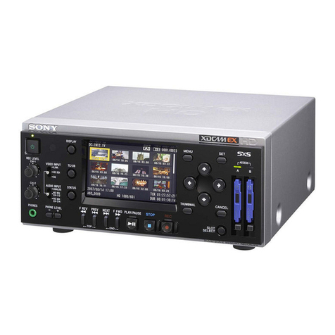
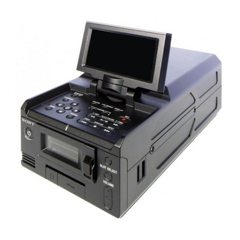
Sony DNW-A100 User manual

DIGITAL VIDEO HYBRID RECORDER
DNW-A100/A100P
DNW-A50/A50P
DNW-A45/A45P
MAINTENANCE MANUAL Part 2
Volume 1 1st Edition (Revised 1)
ANALOG COMPOSITE DECODER BOARD
BKDW-505/506
SDTI INPUT KIT
BKNW-103
ANALOG COMPONENT INPUT BOARD
BKNW-104
AES/EBU I/F KIT
BKNW-105

DNW-A100 Serial No. 10111 and Higher
DNW-A100P (UC) Serial No. 10001 and Higher
DNW-A100P (CE) Serial No. 10001 and Higher
DNW-A50 Serial No. 10001 and Higher
DNW-A50P (UC) Serial No. 10001 and Higher
DNW-A50P (CE) Serial No. 10001 and Higher
DNW-A45 Serial No. 10001 and Higher
DNW-A45P (UC) Serial No. 10001 and Higher
DNW-A45P (CE) Serial No. 10001 and Higher
BKDW-505 Serial No. 10001 and Higher
BKDW-506 (UC) Serial No. 10001 and Higher
BKDW-506 (CE) Serial No. 10001 and Higher
BKNW-103 Serial No. 10001 and Higher
BKNW-104 Serial No. 10001 and Higher
BKNW-105 Serial No. 10001 and Higher
!WARNING
This manual is intended for qualified service personnel only.
To reduce the risk of electric shock, fire or injury, do not perform any servicing other than that
contained in the operating instructions unless you are qualified to do so. Refer all servicing to
qualified service personnel.
!WARNUNG
DieAnleitung ist nur für qualifiziertes Fachpersonal bestimmt.
Alle Wartungsarbeiten dürfen nur von qualifiziertem Fachpersonal ausgeführt werden. Um die
Gefahr eines elektrischen Schlages, Feuergefahr und Verletzungen zu vermeiden, sind bei
Wartungsarbeiten strikt die Angaben in der Anleitung zu befolgen. Andere als die angegeben
Wartungsarbeiten dürfen nur von Personen ausgeführt werden, die eine spezielle Befähigung
dazu besitzen.
!AVERTISSEMENT
Ce manual est destiné uniquement aux personnes compétentes en charge de l’entretien.Afin
de réduire les risques de décharge électrique, d’incendie ou de blessure n’effectuer que les
réparations indiquées dans le mode d’emploi à moins d’être qualifié pour en effectuer d’autres.
Pour toute réparation faire appel à une personne compétente uniquement.
DNW-A100/A50/A45
DNW-A100P/A50P/A45P

1
DNW-A100/A50/A45
DNW-A100P/A50P/A45P
Table of Contents
Manual Structure
Purpose of this manual .............................................................................................. 8
Contents ..................................................................................................................... 8
Related manuals....................................................................................................... 10
Caution for Handing the Unit with Built-in HDDs (for Part 2) ........................ 11
1. Service Overview
1-1. Circuit Protection Device (Fuse and IC Link) ............................................1-1
1-2. Memory IC with Backup Battery................................................................1-2
1-3. NV-RAM.....................................................................................................1-2
1-4. Alignment Tape...........................................................................................1-4
1-5. Extension Board ..........................................................................................1-7
1-6. PLCC IC Removal ......................................................................................1-7
1-7. Service Action after Replacing or Repairing the Mounted Circuit Board ..1-8
1-7-1. AC-169 Board ............................................................................1-8
1-7-2. AD-105 Board (BKNW-104).....................................................1-8
1-7-3. APR-12 Board ............................................................................1-8
1-7-4. APR-13 Board ............................................................................1-8
1-7-5. CCM-15 Board...........................................................................1-8
1-7-6. CL-29 Board...............................................................................1-8
1-7-7. CP-277 Board.............................................................................1-9
1-7-8. CP-278 Board...........................................................................1-10
1-7-9. CP-297 Board...........................................................................1-10
1-7-10. CP-300 Board (BKNW-103)....................................................1-10
1-7-11. CP-301 Board...........................................................................1-10
1-7-12. CP-308 Board (BKNW-105)....................................................1-10
1-7-13. DEC-65 Board (BKDW-505/506) ...........................................1-11
1-7-14. DIF-42 Board ...........................................................................1-11
1-7-15. DIF-44 Board (BKNW-105) ....................................................1-11
1-7-16. DM-89 Board ...........................................................................1-11
1-7-17. DPR-71 Board..........................................................................1-11
1-7-18. DPR-73 Board..........................................................................1-11
1-7-19. DR-315 Board ..........................................................................1-11
1-7-20. EQ-56 Board ............................................................................1-12
1-7-21. FP-91 Board .............................................................................1-12
1-7-22. KY-364 Board..........................................................................1-12
1-7-23. LP-81 Board .............................................................................1-12
1-7-24. MB-648 Board .........................................................................1-12
1-7-25. MS-50 Board............................................................................1-12
1-7-26. PC-70 Board.............................................................................1-12
1-7-27. PD-35 Board.............................................................................1-13

2DNW-A100/A50/A45
DNW-A100P/A50P/A45P
1-7-28. PTC-54 Board ..........................................................................1-13
1-7-29. PTC-59 Board ..........................................................................1-13
1-7-30. PTC-69 Board ..........................................................................1-13
1-7-31. PTC-71 Board ..........................................................................1-13
1-7-32. RM-82 Board ...........................................................................1-13
1-7-33. SE-341 Board ...........................................................................1-13
1-7-34. SE-344 Board ...........................................................................1-13
1-7-35. SE-378 Board ...........................................................................1-13
1-7-36. SS-63 Board .............................................................................1-14
1-7-37. SSX-1 Board ............................................................................1-14
1-7-38. SWC-30 Board .........................................................................1-14
1-7-39. SWC-31 Board .........................................................................1-14
1-7-40. TBC-23 Board ..........................................................................1-14
1-7-41. TBC-24 Board ..........................................................................1-15
1-7-42. TC-96 Board.............................................................................1-15
1-7-43. TR-78 Board.............................................................................1-15
1-7-44. TR-79 Board.............................................................................1-15
1-7-45. VPR-17 Board ..........................................................................1-15
1-7-46. VR-223 Board ..........................................................................1-15
1-7-47. VR-224 Board ..........................................................................1-15
1-8. Perfection after Replacing the Hard Disk Drive .......................................1-16
2. Electrical Alignment Overview
2-1. Notes on Electrical Alignment ....................................................................2-1
2-2. Outline of Electrical Alignment ..................................................................2-1
2-3. Required Equipment/Tools .........................................................................2-2
2-4. Internal Video Test Signal ..........................................................................2-3

3
DNW-A100/A50/A45
DNW-A100P/A50P/A45P
3. Electrical Alignment
3-1. Power Supply Line Alignment....................................................................3-2
3-1-1. Output Voltage Check................................................................3-2
3-1-2. Output Voltage Adjustment .......................................................3-3
3-2. Dial Pulse Adjustment (PTC-69 Board) .....................................................3-4
3-3. Demagnetization Head Driving Voltage Adjustment (MS-50 Board)........3-6
3-4. Servo System Alignment.............................................................................3-7
3-4-1. Adjustment Overview ................................................................3-7
3-4-2. Servo Adjustment Data Initialization.........................................3-8
3-4-3. Servo Continuity Automatic Adjustment...................................3-8
3-4-4. Capstan Free Speed Adjustment ................................................3-8
3-4-5. RF Switching Position Adjustment ............................................3-9
3-5. RF System Alignment (EQ-56 Board)......................................................3-10
3-5-1. Adjustment Overview ..............................................................3-10
3-5-2. Betacam SX Format Overall RF System Adjustment..............3-11
3-5-3. Betacam / Betacam SP Format PB System
(EQ RF Output Level) Adjustment ..........................................3-12
3-5-4. Recording Current Adjustment ................................................3-15
3-6. Audio System Adjustment (APR-12/13 Boards) ......................................3-16
3-6-1. Adjustment Overview ..............................................................3-16
3-6-2. Common Preparation ...............................................................3-18
3-6-3. Analog Audio Outputs (CH1/2/3/4) Adjustment
(APR-13 Board) .......................................................................3-20
3-6-4. Analog Audio Offsets (CH3/4) Adjustment
(APR-13 Board) .......................................................................3-21
3-6-5. Analog Audio Inputs (CH3/4) Adjustment
(APR-13 Board) .......................................................................3-22
3-6-6. Analog Audio Monitor Outputs (L/R) Adjustment
(APR-12 Board) .......................................................................3-23
3-6-7. Analog Audio Offsets (CH1/2) Adjustment
(APR-12 Board) .......................................................................3-24
3-6-8. Analog Audio Inputs (CH1/2) Adjustment
(APR-12 Board) .......................................................................3-25
3-6-9. LAU PB System Adjustment (APR-12 Board)........................3-27
3-7. Video System Alignment (VPR-17 Board)...............................................3-32
3-7-1. Adjustment Overview ..............................................................3-32
3-7-2. Preparation in Standard System ...............................................3-34
3-7-3. Composite Video Output Adjustment (Standard System) .......3-35
3-7-4. Component Video Output Adjustment (Standard System) ......3-37
3-7-5. Component Video Output (Betacam) Adjustment
(525/60 System) .......................................................................3-39
3-7-6. Reference Color Frame Pulse Check
(Standard System only) ............................................................3-41
3-7-7. Internal 4fsc Frequency Adjustment ........................................3-43
3-7-8. Preparation in Another System ................................................3-44
http://getMANUAL.com
4DNW-A100/A50/A45
DNW-A100P/A50P/A45P
3-7-9. Composite Video Output Adjustment (Another System) ........3-45
3-7-10. Component Video Output Adjustment (Another System) .......3-47
3-7-11. Component Video Output (Betacam) Adjustment
(for DNW-A100P/A50P/A45P only in 525/60 System) ..........3-48
3-8. Analog Betacam PB System Alignment ...................................................3-49
3-8-1. Adjustment Overview ..............................................................3-49
3-8-2. Common Preparation ...............................................................3-54
3-8-3. Initial Data Settings ..................................................................3-55
3-8-4. EQ RF Output Level Adjustment .............................................3-56
3-8-5. Cosine Equalizer Adjustment ...................................................3-56
3-8-6. Cosine Equalizer Provisional Adjustment ...............................3-64
3-8-7. DM RF Output Level Adjustment............................................3-66
3-8-8. OMC Carrier Balance Adjustment ...........................................3-68
3-8-9. OMC Carrier Balance Provisional Adjustment........................3-71
3-8-10. Demodulator Limiter Balance Adjustment ..............................3-72
3-8-11. Non-Liner Output Level Adjustment .......................................3-74
3-8-12. PB Frequency Response Adjustment .......................................3-76
3-8-13. Drop-out Compensation Equalizer Adjustment .......................3-82
3-8-14. DM RF Output Level Readjustment ........................................3-83
3-8-15. RF Envelope Adjustment .........................................................3-84
3-8-16. Search Picture Adjustment .......................................................3-86
3-8-17. Guard Band Width Adjustment................................................3-88
3-8-18. Component Output Level Adjustment .....................................3-90
3-8-19. A/D Clamp DC Level Adjustment ...........................................3-93
3-8-20. VCO Lock-in Range Adjustment .............................................3-94
3-8-21. TBC VCO Free-running Adjustment .......................................3-95
3-8-22. FAST VCO Tracking Adjustment ...........................................3-96
3-8-23. PB Video Phase Adjustment ....................................................3-97
3-8-24. TBC Y/C Delay Rough Adjustment ......................................3-100
3-8-25. Impact Error Offset Adjustment.............................................3-102
3-8-26. TBC Y/C Delay Adjustment ..................................................3-103
3-8-27. VISC Phase Adjustment.........................................................3-105
3-9. TBC Remote Control Offset Adjustment (FP-91 Board) .......................3-109
3-10. SDI/SDTI I/O Lines Adjustment (CP-297 Board)..................................3-111
3-10-1. Adjustment Overview ............................................................3-111
3-10-2. VCO Free-running Frequency Automatic Adjustment ..........3-112
3-10-3. VCO Free-running Frequency Manually Adjustment............3-113
3-11. LTC Alignment and Full Erasure Current Check (TC-96 Board) ..........3-114
3-11-1. Adjustment Overview ............................................................3-114
3-11-2. LTC Playback Level Check ...................................................3-115
3-11-3. LTC Recording Level Check .................................................3-116
3-11-4. Full Erasure Current Check....................................................3-117
3-11-5. LTC Erasure Current Check...................................................3-117

5
DNW-A100/A50/A45
DNW-A100P/A50P/A45P
4. Electrical Alignment for Optional Boards
4-1. DEC-65 Board (BKDW-505/506) ..............................................................4-2
4-1-1. Adjustment .................................................................................4-2
4-2. CP-300 Board (BKNW-103).....................................................................4-12
4-2-1. Adjustment ...............................................................................4-12
4-2-2. Operation Check.......................................................................4-14
4-3. AD-105 Board (BKNW-104)....................................................................4-15
4-3-1. Adjustment ...............................................................................4-15
4-4. CP-308 Board and DIF-44 Board (BKNW-105) ......................................4-28
4-4-1. Operation Check.......................................................................4-28
5. Replacement of Main Parts
5-1. General Information for Parts Replacement ...............................................5-1
5-1-1. Index...........................................................................................5-1
5-1-2. Threading End Mode and Unthreading End Mode ....................5-4
5-1-3. L Cassette Position and S Cassette Position ..............................5-6
5-1-4. Basic Knowledge .......................................................................5-8
5-2. Upper Drum Assembly Replacement..........................................................5-9
5-3. Drum Assembly Replacement...................................................................5-18
5-4. Cleaning Roller and Video Head Cleaner Assembly Replacement ..........5-27
5-5. AT Head Cleaner Replacement.................................................................5-32
5-6. Air Filter Replacement..............................................................................5-35
5-7. Pinch Roller Replacement.........................................................................5-37
5-8. CTL Head Replacement............................................................................5-40
5-9. Reel Motor Assembly Replacement..........................................................5-44
5-9-1. Replacement Procedure of the Reel Motor Assembly .............5-44
5-9-2. Reel Motor Shaft Slantness Adjustment ..................................5-52
5-9-3. Cassette Pillar Height Adjustment ...........................................5-55
5-9-4. Reel Table Height Adjustment.................................................5-57
5-9-5. Reel Brake Clearance Check....................................................5-60
5-9-6. Reel Brake Release Amount Adjustment.................................5-61
5-9-7. Reel Table Rotation Sensor Position Adjustment ....................5-63
5-10. Capstan Motor Replacement .....................................................................5-66
5-11. AT Head Replacement ..............................................................................5-71
5-12. Pinch Solenoid Replacement.....................................................................5-76
5-12-1. Replacement Procedure of the Pinch Solenoid ........................5-76
5-12-2. Pinch Press Clearance Adjustment...........................................5-84
5-13. Fan Motor Replacement............................................................................5-86
5-13-1. Fan Motor (Rear) Replacement................................................5-87
5-13-2. Fan Motor (PS) Replacement...................................................5-90
5-13-3. Fan Motor (HDD) and Fan Motor (MD) Replacement............5-91
5-14. Brush Slip Ring Assembly Replacement ..................................................5-97

6DNW-A100/A50/A45
DNW-A100P/A50P/A45P
5-15. Brake Solenoid Replacement ..................................................................5-100
5-16. S Tention Regulator Assembry Replacement .........................................5-110
5-17. T Tention Arm Replacement...................................................................5-112
5-18. T Drawer Arm Replacement ...................................................................5-116
5-18-1. T Drawer Arm Replacement ..................................................5-116
5-18-2. Slant Guide Slantness Adjustment .........................................5-122
5-19. Gear Box Assembly and Threading Motor Replacement .......................5-126
5-20. Threading Ring and Ring Roller Replacement .......................................5-133
5-21. Reel Table Assembly Replacement ........................................................5-149
5-22. Brake Lining Replacement......................................................................5-152
5-23. Tape Guide Replacement ........................................................................5-156
5-24. Tape Cleaner Replacement .....................................................................5-158
5-25. Full-erase Head Replacement .................................................................5-160
5-26. Cleaning Solenoid Replacement .............................................................5-165
5-27. Reel Shift Gear Replacement ..................................................................5-171
5-28. Reel Shift Motor Replacement................................................................5-176
5-29. Cassette Compartment Motor Replacement............................................5-181
5-30. Power Supply Block Replacement..........................................................5-185
5-31. Hard Disk Drive Replacement ................................................................5-189
5-31-1. Caution for Handling the Hard Disk Drive ............................5-189
5-31-2. Removal/Installation of Hard Disk Drive Unit ......................5-189
5-31-3. Hard Disk Drive Replacement ...............................................5-193
5-32. Replacement of Mounted Circuit Board .................................................5-198
5-32-1. CP-277 Board .........................................................................5-198
5-32-2. CP-278 Board .........................................................................5-199
5-32-3. CP-297 Board .........................................................................5-201
5-32-4. CP-300 Board (BKNW-103)..................................................5-202
5-32-5. CP-301 Board .........................................................................5-203
5-32-6. DR-315 Board ........................................................................5-204
5-32-7. FP-91 Board ...........................................................................5-206
5-32-8. KY-364 Board ........................................................................5-208
5-32-9. MB-648 Board .......................................................................5-209
5-32-10. MS-50 Board ..........................................................................5-213
5-32-11. SE-341 Board .........................................................................5-215
5-32-12. SE-378 Board .........................................................................5-216
5-32-13. SWC-30 Board .......................................................................5-217
5-32-14. SWC-31 Board .......................................................................5-220
5-32-15. TC-96 Board...........................................................................5-222
5-32-16. TR-79 Board...........................................................................5-223
5-32-17. VR-223 Board ........................................................................5-224
5-32-18. VR-224 Board ........................................................................5-226

7
DNW-A100/A50/A45
DNW-A100P/A50P/A45P
6. Electrical Alignment after Replacement of Main Parts
6-1. General Information for Electrical Alignment............................................6-1
6-1-1. Notes on Electrical Alignment ...................................................6-1
6-1-2. Equipment and Tools Required..................................................6-2
6-1-3. Content of Alignment Tapes ......................................................6-4
6-2. Servo/EQ Alignment after Replacing the Drum .........................................6-7
6-2-1. Drum Phase Adjustment ............................................................6-8
6-2-2. PB Equalizer Adjustment ...........................................................6-9
6-2-3. Recording Current Adjustment ................................................6-10
6-3. Analog Video Playback System Adjustment after Replacing the Drum ..6-11
6-3-1. Preparation ...............................................................................6-13
6-3-2. EQ RF Output Level Adjustment.............................................6-16
6-3-3. DM RF Output Level Pre-adjustment ......................................6-19
6-3-4. OMC Carrier Balance Adjustment...........................................6-21
6-3-5. OMC Carrier Balance Adjustment (Provisional) .....................6-24
6-3-6. Demodulator Limiter Balance Adjustment ..............................6-24
6-3-7. PB Frequency Response Adjustment .......................................6-27
6-3-8. DM RF Output Level Adjustment............................................6-31
6-3-9. RF Envelope Adjustment .........................................................6-33
6-3-10. Impact Error Offset Adjustment...............................................6-34
6-3-11. TBC Y/C Delay Adjustment ....................................................6-35
6-4. Electrical Adjustment after Replacing the AT Head.................................6-37
6-4-1. Preparation ...............................................................................6-38
6-4-2. LAU PB Frequency Response Adjustment..............................6-40
6-4-3. LAU Dolby Level Adjustment.................................................6-42
6-4-4. LAU PB Level Adjustment ......................................................6-43
6-4-5. LAU PB Phase Adjustment......................................................6-44
6-4-6. LTC Erasure Current Adjustment ............................................6-45
6-4-7. LTC PB Level Check ...............................................................6-45
6-4-8. LTC OA Check ........................................................................6-46
6-4-9. LTC Erase Ratio Check ...........................................................6-47
7. Tape Path Alignment
7-1. Tape Path Adjustment .................................................................................7-1
7-1-1. AT Head Zenith Check and Adjustment ....................................7-6
7-1-2. Tape-running Check and Adjustment ........................................7-8
7-1-3. Video Tracking Check and Adjustment ...................................7-14
7-1-4. CTL Head Height Check and Adjustment ...............................7-26
7-1-5. CTL Head Position Check and Adjustment .............................7-28
7-1-6. AT Head Height Check and Adjustment .................................7-31
7-1-7. AT Head Azimuth Check and Adjustment ..............................7-34
7-1-8. AT Head Head-to-tape Contact Check and Adjustment ..........7-37
7-1-9. AT Head Position Check and Adjustment ...............................7-40
7-1-10. Audio Level Check and Adjustment in REV Mode.................7-42

8DNW-A100/A50/A45
DNW-A100P/A50P/A45P
Purpose of this manual This manual is the Maintenance manual part 2 volume 1 of digital video hybrid
recorder DNW series. DNW series includes the following models.
DNW-A100/A100P
DNW-A50/A50P
DNW-A45/A45P
This Maintenance manual part 2 is intended for use by trained system and service
engineers, and provides the information that premises the parts level service (parts
replacement, guideline for adjustment, schematic diagrams, board layouts, detailed
parts list) . Moreover, provides the information for the following optional boards.
BKDW-505/506 Analog Composite Decoder Board
BKNW-103 SDTI Input Kit
BKNW-104 Analog Component Input Board
BKNW-105 AES/EBU I/F Kit
This manual (volume 1) explains about parts replacement and guideline for adjust-
ment.
Contents This manual is organized by following sections.
Section 1 Service Overview
Explains the information of circuit protection devices, NV-RAMs, alignment tapes,
and extension boards, the removal of PLCC IC, and the service actions after replac-
ing/repairing the mounted circuit boards.
Section 2 Electrical Alignment Overview
Explains the overview for electrical alignment.
Section 3 Electrical Alignment
Explains the electrical alignment for the maintenance of this unit.
Section 4 Electrical Alignment for Optional Boards
Explains the electrical alignment for the maintenance of optional boards.
Section 5 Replacement of Main Parts
Explains the replacement of mechanical parts, power supply unit, hard disk drive
(HDD), and circuit boards.
Section 6 Electrical Alignment after Main Parts Replacement
Explains the electrical alignment associated with replacement of parts that are
described in Section 5.
Section 7 Tape Path Alignment
Explains the tape path alignment after replacement of parts that are described in
Section 5.
Manual Structure
Maintenance manual
part 2 volume 1
(9-967-659- )

9
DNW-A100/A50/A45
DNW-A100P/A50P/A45P
Section 1 Service Overview
Describes the notes on repair parts.
Section 2 Exploded Views
Describes the exploded views and the mechanical parts list (including some electri-
cal parts) .
Section 3 Electrical Parts List
Describes the electrical parts list of each board (including some mechanical parts) .
Moreover, describes the electrical parts list (frame electrical parts list) except on the
board.
Section 4 Electrical Parts List for Optional Boards
Describes the electrical parts list of each optional board (including some mechanical
parts) .
Section 5 Packing Materials and Supplied Accessories List
Describes the packing materials, packing materials for HDD and the supplied
accessories list.
Section 6 Optional Fixtures List
Describes the optional fixtures and maintenance articles list.
Section 1 Semiconductor Pin Assignments
Describes the semiconductor pin assignments.
Section 2 Block Diagrams
Describes the block diagrams of overall and each board.
Section 3 Schematic Diagrams and Frame Wiring
Describes the frame wiring and the schematic diagrams for the unit.
Section 4 Schematic Diagrams for Optional Boards
Describes the schematic diagrams for the optional boards.
Section 5 Board Layouts
Describes the board layouts for the unit and the optional boards.
Maintenance manual
part 2 volume 2
(9-967-660- )
Maintenance manual
part 2 volume 3
(9-967-662- )

10 DNW-A100/A50/A45
DNW-A100P/A50P/A45P
Related manuals Besides this “Maintenance manual part 2”, the following manuals are available for
digital video hybrid recorder DNW series.
..
..
.Operation Manual (Supplied with the DNW.)
This manual is necessary for application and operation (and installation ) of the
DNW.
..
..
.Maintenance Manual Part 1 (Supplied with the DNW.)
This manual describes the information that is required to install, maintenance
information, and the information for service such as replacement of plug-in
boards.
..
..
.Protocol Manual of Remote (9-pin) Connector (available on request)
This manual explains the protocol for controlling the VTR via the RS-422A (9-pin
serial remote) . If this manual is required, please contact your local Sony Sales
Office/Service Center.

11
DNW-A100/A50/A45
DNW-A100P/A50P/A45P
This unit has two built-in hard disk drives (HDDs). Pay careful attention to the followings and perform
operations with extra care when installing, servicing, and maintaining this unit.
Never give any mechanical shock and vibration
This may cause an HDD trouble or destroy the data in HDD.
.Pack this unit using the specified packing materials when carrying the unit. Use a cart with less-
vibration when carrying this unit by a cart. If an excessive mechanical shock and vibration are applied,
the HDD may be damaged.
.Never move this unit under power-on state. Take out or insert this unit from or into the rack in a state of
powering off. Also never install or remove the cabinet under power-on state.
.When putting the unit on the floor, put this unit gently with the four specified feet which is attached to
the bottom of the unit on the floor. If there are no feet on the bottom, attach them before putting this
unit, or put this unit gently so that no sound is generated.
Never operate the unit for 30 seconds after the power is turned off
The disks in HDD rotate by inertia for a while after the power is turned off. In this case, the heads are in
the unstable state. During this period, the HDD is more sensitive to a mechanical shock and vibration than
during power on state. Never give even a slight shock at least 30 seconds after the power is turned off.
Operations can be initiated (because the disks stop) after 30 seconds or more.
In the event of trouble in HDD
If there is something wrong with the HDD of this unit (a failure occurs in the HDD), handle this unit in
the same manner as described above. This protects the HDD from increase of the damage till confirming
the contents of the failure or analyzing the failure.
Pay careful attention to the following when handlings the HDD alone.
Notes when carrying or keeping the HDD
Pack the HDD using the specified packing materials when carrying or keeping the HDD. Moreover,
choose the method which the HDD is not subject to the vibration when carrying.
Caution for Handling the Unit with Built-in HDDs (for Part 2)

12 DNW-A100/A50/A45
DNW-A100P/A50P/A45P
Notes when replacing the HDD
Follow the procedure (described in Section 5) when replacing the HDD.
.If an excessive mechanical shock and vibration are applied, the unpacked HDD may be damaged. Place
the unpacked HDD in a horizonal position (with the printed board side up) . Moreover, it is recom-
mended that the unpacked HDD is put on the specified HDD cushion.
.Use the specified shockless torque screwdriver when tightening and removing the screw during replac-
ing the HDD.
The HDD cushion and shockless torque screwdriver are available as a fixture.
HDD cushion : Part No. J-6530-060-A
Shockless torque screwdriver: Part No. J-6530-070-A
.HDD is easily affected by static electricity. Take measures against static electricity such as establishing
a ground, then install the HDD.
Handling of failed HDD
Handle the HDD that is removed because of a trouble or failure in the same manner as a normal HDD
following above precautions. Then pack the HDD using the specified packing materials, contact your
local Sony Sales Office/Service Center.

1-1
DNW-A100/A50/A45
DNW-A100P/A50P/A45P
Section 1
Service Overview
Board name Ref. No.(address) Description Part No. Remarks
AD-105 board PS500 (B-7) Fuse (chip) 2 A, 125 V !1-533-351-11 For BKNW-104
PS501 (B-7)
APR-12 board PS900 (F-7) Fuse (chip) 0.5 A, 125 V !1-533-271-21
APR-13 board PS700 (G-7) Fuse (chip) 0.5 A, 125 V !1-533-271-21
CP-297 board PS100 (C-1) Fuse (chip) 1 A, 125 V !1-533-380-21
PS101 (C-1)
CP-300 board PS100 (A-1) Fuse (chip) 1 A, 125 V !1-533-380-21 For BKNW-103
PS101 (A-1)
DEC-65 board PS901 (C-6) Fuse (chip) 4 A, 125 V !1-533-272-11 For BKDW-505/506 (UC)
IC link (chip) 4 A !1-533-348-11 For BKDW-506 (CE)
DIF-42 board PS500 (G-5) Fuse (chip) 1 A, 125 V !1-533-380-21
PS501 (G-6)
DIF-44 board PS401 (G-7) Fuse (chip) 0.5 A, 125 V !1-533-271-21 For BKNW-105
DPR-71 board PS11 (G-7) Fuse (chip) 4 A, 125 V !1-533-272-11
PS12 (G-7)
PS13 (H-7)
PS15 (E-7)
DPR-73 board PS100 (E-7) Fuse (chip) 4 A, 125 V !1-533-272-11
PS101 (E-7)
PS102 (D-7)
DR-315 board PS1 (A-5) Fuse (chip) 5 A, 125 V !1-533-275-21
EQ-56 board PS1 (G-7) IC link (chip) 4 A !1-533-348-11
SE-378 board F1 Fuse (chip) 2 A, 125 V !1-533-351-11
F3
F2 Thermal fuse 115 dC, 3 A, 125 V !1-533-251-11
F4
SS-63 board PS100 (E-7) Fuse (chip) 3.15 A, 125 V !1-533-266-11
PS101 (E-7) Fuse (chip) 0.5 A, 125 V !1-533-271-21
SSX-1 board PS100 (F-7) Fuse (chip) 5 A, 125 V !1-533-275-21
PS101 (F-7) Fuse (chip) 2 A, 125 V !1-533-351-11
PS400 (F-2)
TBC-23 board PS1 (C-7) Fuse (chip) 0.5 A, 125 V !1-533-271-21
TC-96 board PS200 (D-1) Fuse (chip) 0.4 A, 125 V !1-533-724-11
PS300 (D-1)
VPR-17 board PS900 (H-12) Fuse (chip) 5 A, 125 V !1-533-275-21
Note: (address) means the mounted address of fuse or IC link.
Fuses or IC links for circuit protection are mounted on the
boards of the VTR and on the optional boards.
A fuse or IC link will blow when abnormality occurs and
an over-current flows (or over-heat occurs) in the equip-
ment. Be sure to replace it with the specified fuse or IC
link as shown below after tracing and removing the root of
the fuse-blowing.
c
Use the specified part only
The fuse and IC link are critical parts to safe operation.
Replace these components with Sony parts whose part
numbers appear in this manual published by Sony. If not,
this may cause a fire or electric shock. Be sure to use the
specified component in this manual
1-1. Circuit Protection Device (Fuse and IC Link)
http://getMANUAL.com
1-2 DNW-A00/A50/A45
DNW-A100P/A50P/A45P
1-2. Memory IC with Backup Battery
1-3. NV-RAM
1-2. Memory IC with Backup Battery
Memory IC (RAM) with backup battery is equipped on
IC710 of the SS-63 board.
This IC is used to store the setting data of setup menu, etc.
Besides it has an RTC (Real Time Clock) function, which
is also used in the VTR.
Owing to this battery, even if the external power is cut off,
this IC can maintain the stored data and the RTC continues
operating.
However, if the battery life comes to end with the external
power was cut off, memory can not maintain the stored
data and the RTC is failing to function.
Life of the backup battery
Life of the backup battery is guaranteed for at least ten
years in the absence of external power after this IC manu-
factured. Therefore, the replacement timing for IC710
varies depending on the operating condition (power-on
time).
Replacement time
When life-ending the battery while the VTR is powered
off, the RTC is failing to function.
If powered on in such a condition, the error code 96, sub
error message "CALENDAR CLOCK" will be displayed.
This message is displayed, be sure to replace IC710.
n
.This sub error message is displayed on the video monitor
connected to the VIDEO OUTPUT COMPOSITE 3
(SUPER) connector with the CHARACTER switch
turned on.
Other sub error messages, if present, are also displayed
together.
.When the error code 96, sub error message “CALEN-
DAR CLOCK” is displayed, the date in the calendar will
be reset to 1/Nov./1996.
You can check the date in calendar/clock using the error
logger display mode (M2 : ERROR LOGGER) in the
maintenance mode.
n
After replacing IC710, make/change settings of various
data and correct the calendar/clock.
Refer to “1-3. NV-RAM” for details.
1-3. NV-RAM
There are the NV-RAMs (EEP-ROM, and RAM with
backup battery) and EVR ICs used on the boards (includ-
ing optional boards) in the VTR. These devices store the
adjustment data, various setting data for the VTR, data for
the hours meters and error log respectively, etc.
EEP-ROM: Electric Erasable P-ROM
EVR: Electric Variable Resister (D/A converter with EEP-ROM)
After replacing above-mentioned device, take the follow-
ing service actions.
“Service action after replacing” and “Stored data” are
listed on next page.
IC710 on the SS-63 board is the only NV-RAM with
backup battery.
n
After replacing the NV-RAM, NV-RAM error (error code
96, 97, or 98) will occur at power-on.
After replacing IC710/SS-63: Occurs Error code 96.
After replacing IC9/MS-50: Occurs Error code 97.
After replacing IC908/DM-89: Occurs Error code 98.
After replacing IC900/EQ-56: Occurs Error code 98.
After replacing IC200/TBC-23: Occurs Error code 98.
When replacing IC710 on the SS-63 board, NV-RAM error
(error code 96) will be occur once at the first power-on. At
the second power-on and later, this error will not occur.

1-3
DNW-A100/A50/A45
DNW-A100P/A50P/A45P
Board / Ref.No. Type Stored data Service action after replacing
AD-105 / IC602 EVR IC Adjustment data for AD-105 board Readjust the AD-105 board.
(BKNW-104) (Perform Section 4-3.)
CP-297 / IC308 EVR IC Adjustment data for CP-297 board Readjust the CP-297 board (SDI/SDTI input/
output system). (Perform Section 3-9.)
DEC-65 / IC301 EVR IC Adjustment data for DEC-65 board Readjust the DEC-65 board.
(Perform Section 4-1.)
DM-89 / IC908 NV-RAM Adjustment data for DM-89 board Readjust the DM-89 board.
(Perform the electrical adjustments in “6-4.
DM-89 Board Replacement” of the maintenance
manual Part 1.)
EQ-56 / IC900 NV-RAM Adjustment data for EQ-56 board Readjust the EQ-56 board.
(Perform the electrical adjustments in “6-5. EQ-
56 Board Replacement” of the maintenance
manual Part 1.)
MS-50 / IC9 NV-RAM Adjustment data for VTR servo system After the initialization, readjust the VTR servo
system. (Refer to Section 3-4.)
Hours meter data None (All data are lost and automatically
initialized to count zero.)
Serial No. Set by the menu C41 of the maintenance mode.
Head room of the audio level meter Set by the menu C47 of the maintenance mode.
(When setting it to except 20 dB.)
SS-63 / IC710 NV-RAM Setting data of setup menu Set the setup menu again.
Error logs data None (All data are lost.)
ID code data Set by the ISR (Interactive Status Reporting)
application software.
Calendar/clock Set the calendar and clock again.
(Refer to “6-6-2. Error Logging Data Clean and
Calender/Clock Setting” of the maintenance
manual Part 1.)
TBC-23 / IC200 NV-RAM Adjustment data for TBC-23 board Readjust the TBC-23 board.
(Perform the electrical adjustments in “6-7.
TBC-23 Board Replacement” of the mainte-
nance manual Part 1.)
VPR-17 / IC909 EVR IC Adjustment data for VPR-17 board Readjust the VPR-17 board.
(Perform the electrical adjustments in “6-9.
VPR-17 Board Replacement” of the mainte-
nance manual Part 1.)
1-3. NV-RAM

1-4 DNW-A00/A50/A45
DNW-A100P/A50P/A45P
1-4. Alignment Tape
Describes the alignment tapes used for adjusting the unit.
1. SR5-1 (SONY part No. 8-960-075-01): For 525/60 system
SR5-1P(SONY part No. 8-960-075-51): For 625/50 system
Used for video/audio adjustment.
Time (min. : sec.) Digital video Digital audio CTL track
0:00 - 100 % color-bar 1 kHz sine wave, _20 dB FS CTL
2:00 - 100 % color-bar 1 kHz sine wave, 0 dB FS CTL
4:00 - 100 % color-bar _∞dB FS CTL
6:00 - 100 % color-bar 20 Hz sine wave, _20 dB FS CTL
8:00 - 100 % color-bar 20 kHz sine wave, _20 dB FS CTL
10:00 - Ramp 1 kHz sine wave, _20 dB FS CTL
12:00 - Ramp 1 kHz sine wave, 0 dB FS CTL
14:00 - Ramp _∞dB FS CTL
16:00 - Ramp 20 Hz sine wave, _20 dB FS CTL
18:00 - Ramp 20 kHz sine wave, _20 dB FS CTL
20:00 - 100 % color-bar 1 kHz sine wave, _20 dB FS CTL
22:00 - 100 % color-bar 1 kHz sine wave, 0 dB FS CTL
24:00 - 100 % color-bar _∞dB FS CTL
26:00 - 100 % color-bar 20 Hz sine wave, _20 dB FS CTL
28:00 - 30:00 100 % color-bar 20 kHz sine wave, _20 dB FS CTL
2. SR2-1 (SONY part No. 8-960-075-11) :For 525/60 system
SR2-1P(SONY part No. 8-960-075-61) :For 625/50 system
Used for servo adjustment.
Time (min. : sec.) Digital video Digital audio CTL track
00:00- 3.212 MHz (A CH only) SR2-1: 3 kHz, 0 VU CTL
(Pulse*) SR2-1P: 3.15 kHz, 0 VU
15:00 - A CH : 3.212 MHz SR2-1: 3 kHz, 0 VU CTL
B CH : 6.424 MHz SR2-1P: 3.15 kHz, 0 VU
20:00 - 12.848 MHz (All CH) SR2-1: 3 kHz, 0 VU CTL
SR2-1P: 3.15 kHz, 0 VU
25:00 - 27:00 100 % color-bar (All CH) No signal CTL
*: The time code data is not recorded on the time code track during pulse portion (00:00 to 15:00). This portion is recorded the duty 7:3
pulse on the CTL track. Therefore, when playing back this portion, time data which is interpolated by the time code signal is
displayed.
3. CR2-1B (SONY part No. 8-960-096-01) : For analog Betacam, NTSC
CR2-1B PS (SONY part No. 8-960-096-51) : For analog Betacam, PAL
Used for tracking adjustment.
Time (min. : sec.) Video Track AFM LAU track CTL track
00:00 -28:00 Y : 4 MHz No signal No signal CTL
(Pulse*) C : 5 MHz
*: The time code data is not recorded on the time code track of this tape. But the duty 7:3 pulse is recorded on the time code track.
Therefore, when playing back this tape, time data which is interpolated by the CTL signal is displayed.
1-4. Alignment Tape

1-5
DNW-A100/A50/A45
DNW-A100P/A50P/A45P
4. CR5-1B (SONY part No. 8-960-096-41): For analog Betacam, NTSC
CR5-1B PS (SONY part No. 8-960-096-91): For analog Betacam, PAL
Used for Betacam video adjustment.
Time (min. : sec.) Video AFM*LAU tracks CTL track
0:00 - RF sweep No signal No signal CTL
2:00 - 60 % H sweep (CTDM) No signal No signal CTL
5:00 - Pulse & Bar (CTDM) No signal No signal CTL
8:00 - 60 % multi-burst No signal No signal CTL
11:00 - Pulse & Bar No signal No signal CTL
14:00 - CR5-1B: 75 % color-bar 400 kHz sine wave No signal CTL
CR5-1B PS: 100 % color-bar with 25 kHz deviation
16:30 - CR5-1B: 75 % color-bar 400 kHz sine wave No signal CTL
CR5-1B PS: 100 % color-bar with 75 kHz deviation
17:00 - CR5-1B: 50 % bowtie & 12.5T No signal No signal CTL
CR5-1B PS: 50 % bowtie & 10T
19:00 - Line 17 No signal No signal CTL
22:00 - Quad phase No signal No signal CTL
24:00 - Flat filed No signal No signal CTL
26:00 - CR5-1B: 75 % color-bar No signal No signal CTL
with Drop-out
CR5-1B PS: 100 % color-bar
with Drop-out
28:00 - 30:00 Composite V sweep with VISC No signal No signal CTL
*: DNW-A100/A50/A45/A100P/A50P/A45P can not play back AFM part.
5. CR5-2A (SONY part No. 8-960-097-44): For analog Betacam, NTSC
CR5-2A PS (SONY part No. 8-960-098-44): For analog Betacam, PAL
Used for Betacam video adjustment.
Time (min. : sec.) Video LAU tracks CTL track
0:00 - 75 % color-bar No signal CTL
3:00 - 60 % multi-burst No signal CTL
6:00 - CR5-2A: 50 % bowtie & 12.5T No signal CTL
CR5-2A PS: 50 % bowtie & 10T
9:00 - Pulse & Bar No signal CTL
11:00 - Quad phase No signal CTL
13:00 - 15:00 Composite monoscope (Switching position is shifted.) No signal CTL
1-4. Alignment Tape

1-6 DNW-A00/A50/A45
DNW-A100P/A50P/A45P
6. CR8-1A (SONY part No. 8-960-097-45): For analog Betacam, NTSC
CR8-1A PS (SONY part No. 8-960-098-45): For analog Betacam, PAL
Used for Betacam audio adjustment.
Time (min. : sec.) LAU tracks CTL track Video
0:00 - 1 kHz sine wave, 0 VU CTL No signal
2:55 - No signal CTL No signal
3:00 - 10 kHz sine wave, _10 VU CTL No signal
4:55 - No signal CTL No signal
5:00 - 1 kHz sine wave, _20 VU CTL No signal
5:55 - No signal CTL No signal
6:00 - 40 Hz sine wave, _20 VU CTL No signal
6:25 - No signal CTL No signal
6:30 - 7 kHz sine wave, _20 VU CTL No signal
6:55 - No signal CTL No signal
7:00 - 10 kHz sine wave, _20 VU CTL No signal
7:25 - No signal CTL No signal
7:30 - 15 kHz sine wave, _20 VU CTL No signal
7:55 - No signal CTL No signal
8:00 - 10:00 1 kHz sine wave, 0 VU 1 kHz sine wave, 0 VU No signal
7. CR8-1B PS (SONY part No. 8-960-096-86): For analog Betacam, PAL
Used for Betacam audio adjustment.
Time (min. : sec.) LAU tracks CTL track Video AFM
0:00 - 1 kHz sine wave, 0 VU CTL No signal No signal
2:55 - No signal CTL No signal No signal
3:00 - 15 kHz sine wave, 0 VU CTL No signal No signal
4:55 - No signal CTL No signal No signal
5:00 - 1 kHz sine wave, _20 VU CTL No signal No signal
5:55 - No signal CTL No signal No signal
6:00 - 40 Hz sine wave, _20 VU CTL No signal No signal
6:25 - No signal CTL No signal No signal
6:30 - 7 kHz sine wave, _20 VU CTL No signal No signal
6:55 - No signal CTL No signal No signal
7:00 - 10 kHz sine wave, _20 VU CTL No signal No signal
7:25 - No signal CTL No signal No signal
7:30 - 15 kHz sine wave, _20 VU CTL No signal No signal
7:55 - 8:00 No signal CTL No signal No signal
1-4. Alignment Tape
Other manuals for DNW-A100
4
This manual suits for next models
5
Table of contents
Other Sony Measuring Instrument manuals

Sony
Sony M-640V - Microcassette Recorder User manual

Sony
Sony M-527V User manual

Sony
Sony DT12N User manual

Sony
Sony DG10B Series User manual

Sony
Sony PWS-100TD1 User manual

Sony
Sony APR-5000 User manual

Sony
Sony MSZ-2100G User manual

Sony
Sony DVW-250 User manual

Sony
Sony TC-580 User manual

Sony
Sony MZ-N920 User manual
Popular Measuring Instrument manuals by other brands

Cooper Atkins
Cooper Atkins HACCP Manager ENTERPRISE 37200 manual

Ambient Weather
Ambient Weather WH31-SRS Installation

Omron
Omron HEM-RML30 Instructions for use

Nokeval
Nokeval Solid-Sky-2Pro-DIO-RS485 manual

Cirris
Cirris Signature 1000R+ user guide

Endress+Hauser
Endress+Hauser Proline Promag 55 operating manual