Diatip CD 600 Economy User manual
Midhage Diatip AB May 2003
1
RETIPPING SYSTEM
CD 600 Economy
For core bit diameters and lengths 35 – 600 mm
Operators Manual
Midhage Diatip AB May 2003
2
DECLARATION OF CONTENTS
Assembly for CD 3
Core bit holders 3
Operating instructions and how to cut of the worn part of the drill bit and
make notches
4
Changing the Matrix and Knife 7
Maintenance 8
Serial number and patent number plate 9
Warranties 9
Adapters 9
Segment- and Index plate Guide 11
Guide on matrixes and knives 12
Straight off Cutting Guide 13
Fittings
Column extension with extra 900 mm
Midhage Diatip AB
Hallandsvägen 21
Box 1020
SE - 269 21 Båstad
Sweden
Tel. + 46 (0) 431 710 09
Fax. + 46 (0) 431 754 07
E-mail: [email protected]
Internet: www.diatip.com

Midhage Diatip AB May 2003
3
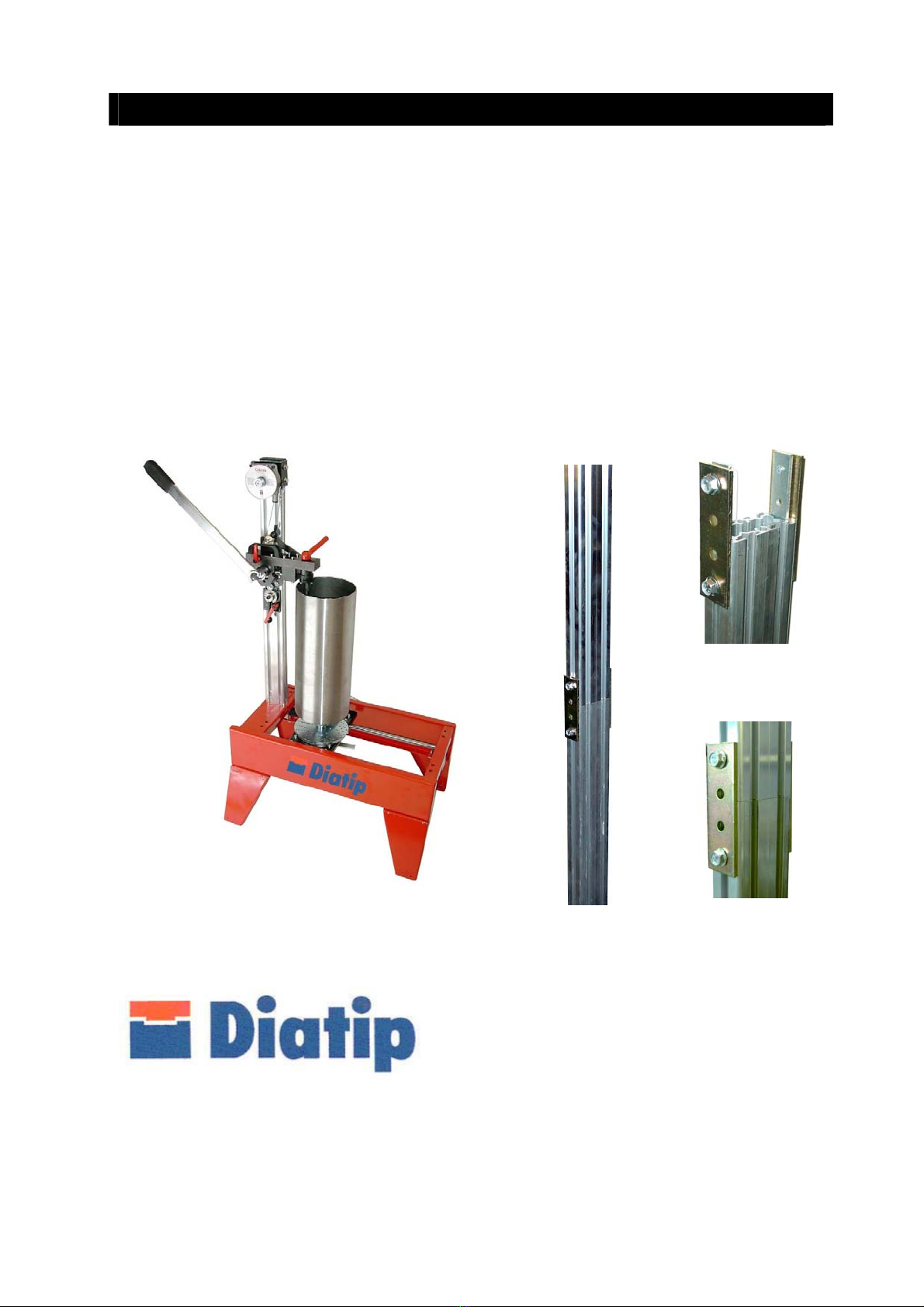
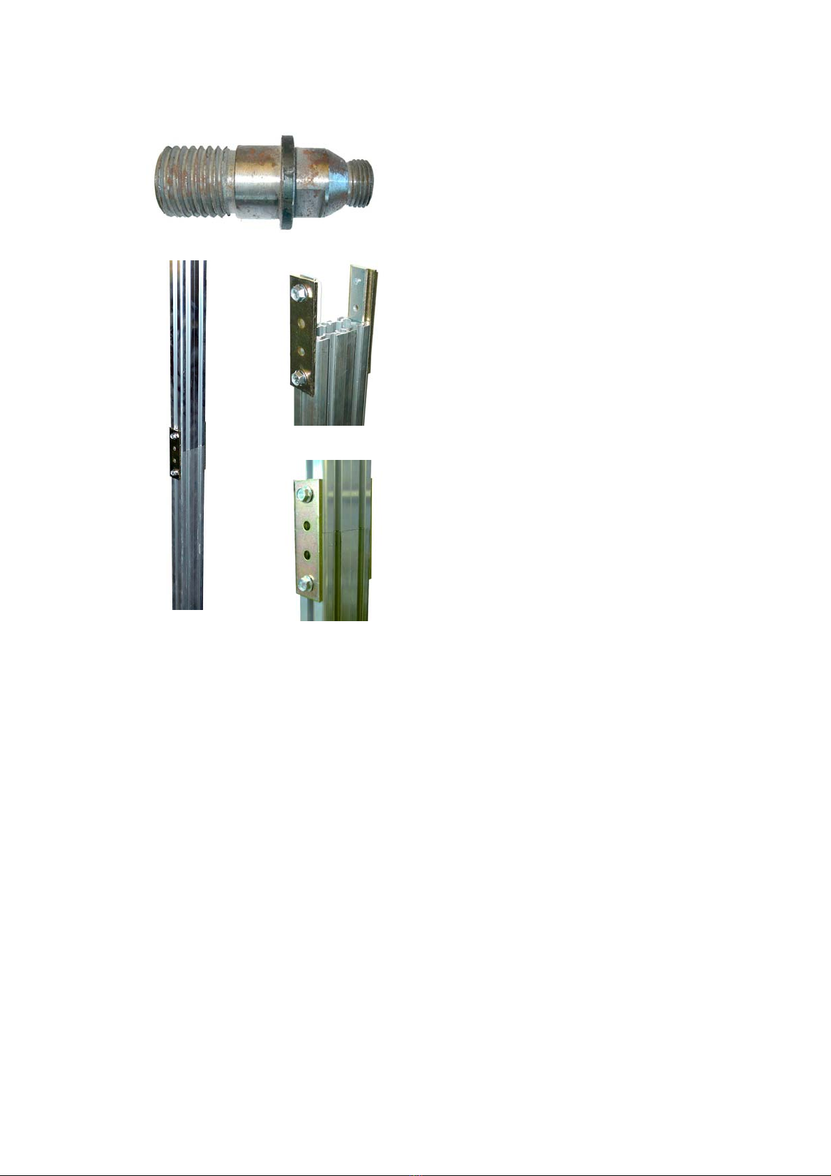
ASSEMBLY FOR COLUMBI CD 600
1
The column is demounted when
delivering.
2
Mount the column with enclosed fittings
at the holder as follows;
Above = 2 bolts with square plates to
fit in to the profiles
Underneath = 2 taps with brass nuts
3
Glue on the two plastic covers on top of
the column and mount the legs
CORE BIT HOLDERS
UNC (1 ¼”) core bit holder
CRI 28 PIXIE (28mm) core bit holder
The CD is equipped either with an UNC
threading or a CRI 28 PIXIE threading
(only for Scandinavia)
Adapters – see page 9 (Optional)
Midhage Diatip AB May 2003
4
OPERATING INSTRUCTIONS and HOW TO CUT OFF THE
WORN PART OF THE DRILL BIT AND MAKE NOTCHES
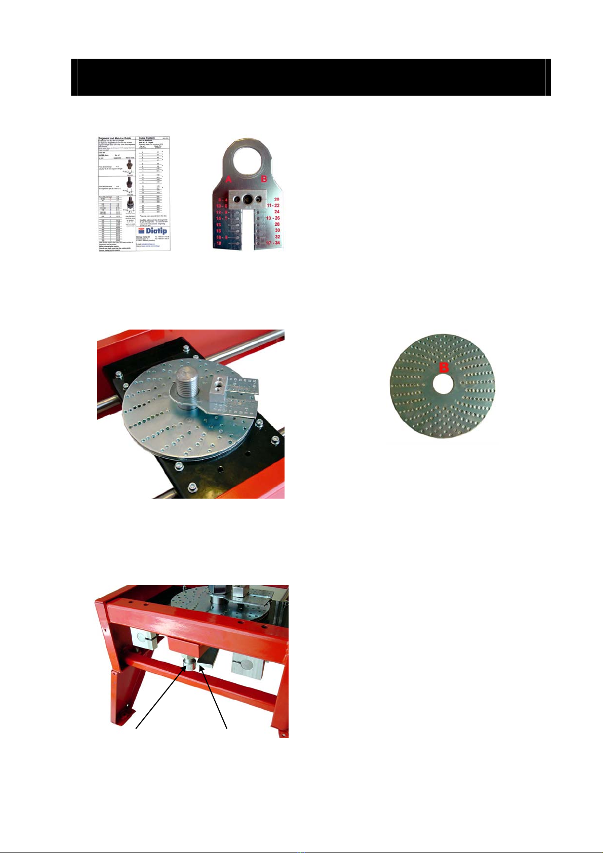
Segment guide Index pin holder
1
Decide the number of segments that
should be rebrazed on the new rim of the
core bit. Adjust the index pin holder on
the scale that positions the pin over the
index plate. (Refer to the segment guide
located at the end of this manual).
2
Select the side (A or B) of the indexing
plate that corresponds to the core bit
dimensions.
Index plate – this image shows side B
Make sure the surfaces are clean before
placing the index plate on the blank base
plate. Then place the index pin holder in
position over the index plate.
When mounting the core bit the guide pin
should always lay in one of the holes of
the Index plate
2 1
3
Lock the core bit by sliding the core bit
attachment to the end of the slides
(opposite from cutter head). Then twist
the barrel clockwise until the level (1) in
the bottom reach the stop bolt (2). Turn
the barrel so it is fasten properly on to the
core bit attachment. When demounting
the barrel do the same procedure but the
opposite way

Midhage Diatip AB May 2003
5
4 The matrix A1 has three different radii.
Choose which radius is suitable for the
core bit. (Position "D" is only for the 16
mm or 20 mm matrix):
Ø 55-90 mm A
Ø 90-200 mm B
Ø > 225 mm C
Ø > 35 mm D
See also the red plate on the tool set
The matrix A2 and A3 are for radii >/= 35
mm resp. >/= 45 mm
To change position of the matrix loosen
the handle which locks the matrix and
lower enough for the guide pin on the
bottom of the head to come free
VERY IMPORTANT
Guide Pin
5
Be sure that the guide pin on the bottom
of the cutter head fits into the hole on top
of the matrix for the new position
6
Tighten the handle clockwise. After the
matrix is secured in position carefully
check that the cutting knife moves freely
into the matrix.

Midhage Diatip AB May 2003
6
A Balance
block
B
E D F C
7
8
9
10
Loosen the locking lever (A) on the tool.
Lower the cutter head over the edge of
the bit (use the handle (B)) until the
cutting knife (C) is below the worn part of
the barrel and the matrix is inside the
barrel. Make sure that no segment parts
remain where the cut is to be made.
Lock the cutter head in position by
turning the lever (A). (The lever is spring
loaded and can be positioned by lifting
the handle from the shaft and then
turning.)
Move up the height adjuster (D) close to
the wheel (E) underneath on the cutting
tool and lock the lever (F).
Cut the slots for the segments as the
index pin drops into position on the index
plate. Turn the bit clockwise to prevent
unscrewing from the threaded bolt on the
mounting attachment.
Height adjuster
G
11 After the first round, loosen the locking
lever (A) and raise smoothly the cutter
head by lifting up the handle (G) to the
required depth of the notched seats 0 – 5
mm (0” - .197”).
Each line on the scale corresponds to
approximately 1 mm.
Lock the cutter head in its new position
with the lever (A) and, this time, cut
between the slots which were cut for the
segments. Cut all the way around and the
top of the core bit can easily be removed.
Now ready for brazing!
1:st round 2:nd round Remove the worn part
slots notched seats

Midhage Diatip AB May 2003
7
CHANGING THE MATRIX AND KNIFE
1
Remove the existing matrix by turning the
handle counter clockwise. Place the
cutting handle so that the blade stays in
its back position.
2
Loosen the allen screw which holds
existing blade. Pull it out and replace with
the new cutting blade and re-tighten.
3
Insert the new matrix. If the replacement
matrix and blade is the 16 mm or 20 mm
size the arrow on the top must then point
to the "D" position. Tighten the handle.
Guide Pin
4
Be sure that the guide pin in the bottom of
the cutter head fits into the hole on the top
of the matrix.
5
By moving the cutting handle back and
forward, check to make sure that the
blade slides accurately into the matrix and
tighten the handle clockwise.
Midhage Diatip AB May 2003
8
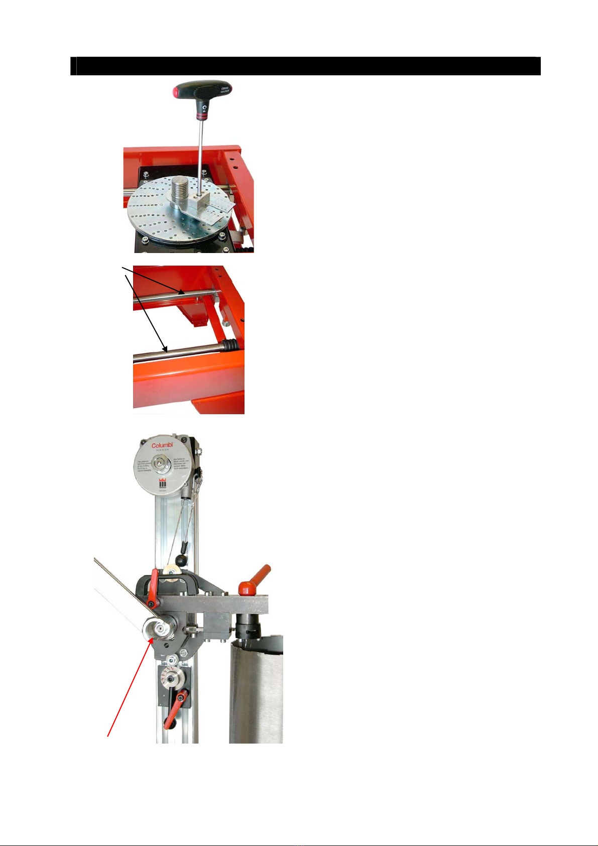
MAINTENANCE
1
Adjust the height of the guide pin if the bit
runs heavily, or too easily, between the
stops on the indexing disc.
H
2
Keep the sliding shafts (H) clean from
concrete dust and cutting parts. Lubricate
the shaft now and then.
I
3
Lubricate the excenter wheel by the
cutting handle (I) now and than.

Midhage Diatip AB May 2003
9
SERIAL AND PATENT NUMBER PLATE
1
The serial number plate is placed inside
the bas frame on the short side
WARRANTIES
Warranties
1
2 years on the machineries except on
wear-out parts such as knives and
matrixes
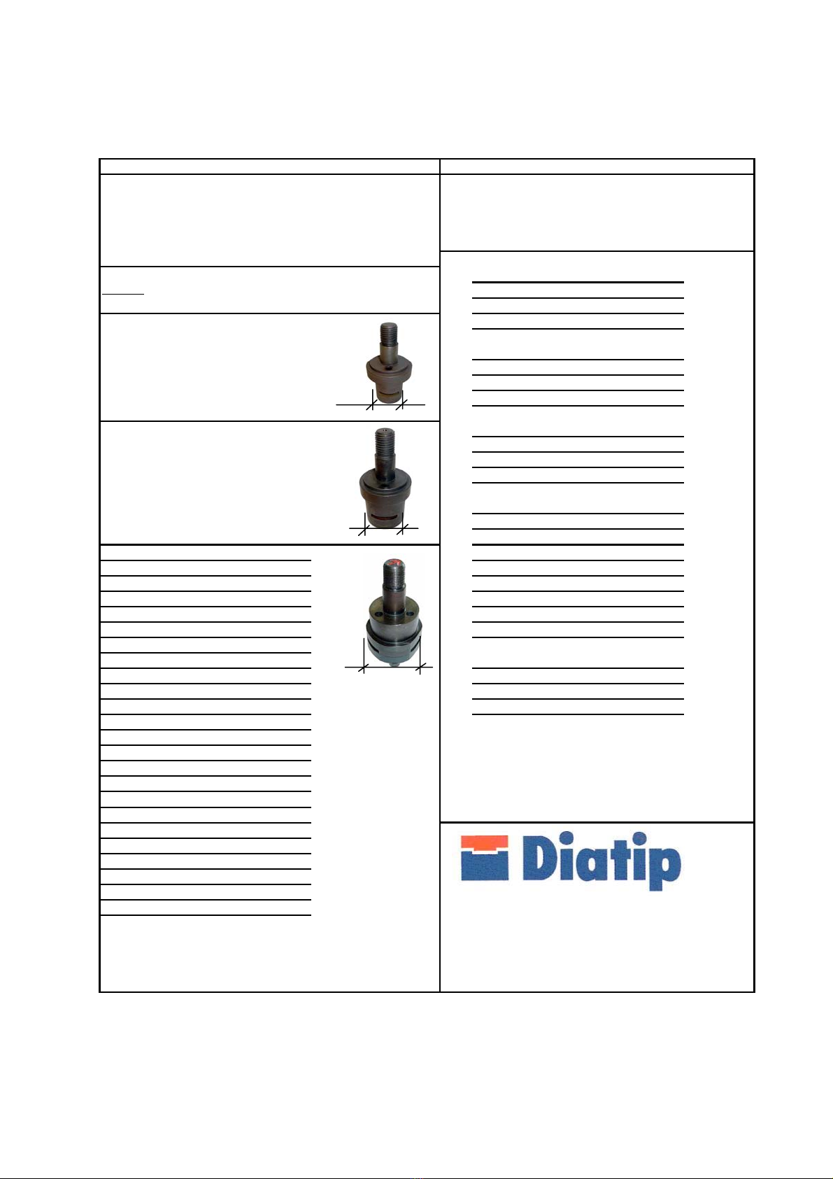
ADAPTERS (Optional)
1
Adapter - from PIXIE CRI 28 mm to
UNC 1 ¼” (Optional)
Article No 010103
2
Adapter – from UNC 1 ¼” to PIXIE CRI
28 mm (Optional)
Article No 010301
3
Changeover Adapter with inside
threading - PIXIE CRI 28 mm to UNC ½”
(Optional)
Article No 010102
4
Changeover adapter with inside
threading – UNC 1 ¼” to UNC ½”
(Optional)
Article No 010302
5
Changeover adapter with outside
threading - PIXIE CRI 28mm to UNC
½ “ (Optional)
Article No 010201
Midhage Diatip AB May 2003
10
6
Changeover adapter with outside
threading – UNC 1 ¼” to UNC ½”
(Optional)
Article No 010203
Fittings
7
Column extension (option) with extra
900 mm
Article No 191 004
Midhage Diatip AB May 2003
11
Segment and Matrix Guide Index System April 2002
for 24 mm and 25,4 mm (1") length for 4-34 segments
of Diamond Segments (for 20 mm resp. 16 mm Plate A + B, 2 sides
segment length about 15% resp. 30% more segments Fork with Guide Pin numbered 4-34
are needed) No. of Guide Pin
Up to outer diam. 31,75 mm (1 1/4") of the core drill, mainly segments position
diamnond rings are used
Core Bit 4A4
*
OUTER diam. No. of 5A5
*
in mm segments Matrix used 6A6
*
7A7
*
8A8
From 35 and larger 4-5 A2 9A9
*
only for 16-20 mm segment length 10 A10
30 mm 11 B11 *
one slot
12 A12
13 B13 *
14 A14
15 A15
From 45 and larger 4-5 A3
for segments upto 25,4 mm (1") 16 A16
40 mm 17 B17 *
one slot 18 A18
From 55 and larger 4-6 19 A19
60-85 A5-6
90 A6-7 20 B20
22 B22
100 B7-8 A1 24 B24
110 B8-9 26 B26
115-132 B9-10
138 B9-11 48 mm 28 B28
150-160 B10-12 30 B30
165-180 B12-14 with three slots, 32 B32
200 B13-15 three diameters 34 B34
and a red arrow
225 C16-18 for position *Use only every second hole in the disc
250 C17-20 A,Bor C
275 C18-20 (see the middle Core Bits with more than 34 segments
300 C19-24 column next) 36 upto 68 segments - cut a second time
350 C20-28 between the indexed slots - beginning
400 C22-30 at A18 upto B34.
450 C24-30
500 C26-32
550 C28-34
600 C30-38
650 C32-40
700 C34-42 Midhage Diatip AB Tel.: +46 431 710 09
With 3-side seats in the tube, the lower number of segments Hallandsvägen 21 Fax: +46 431 754 07
can be chosen. When changing the matrix: S- 269 21 Båstad (Sweden)
Check and make sure that the cutting knife moves
freely into the matrix. E-mail: diatip@midhage.se
Internet: www.swede.com/midhage

Midhage Diatip AB May 2003
12
04-2002
For Matrices with horizontal Knives
Segment slots/openings for
lengths CD 7-28
A
From outer-Ø 55 mm (2 1/4") >
(and larger)
(3 different radiis)
A
20 mm Art. No 550520 800520
A1: The outer dia of the
24 mm "- 550524 800524
Matrix = 48 mm
25,4 mm "- 550525 800525
From outer-Ø 35 mm (1 3/8")
16 mm Art. No 350516 800516
20 mm "- 350520 800520
A2: The outer dia of the
Matrix = 30 mm
Also for other lengths of segments from 5-19 mm - ask for offer!
From outer-Ø 45 mm (1 3/4")
24 mm "- 500524 800524
25,4 mm "- 500525 800525
A3: The outer dia of the
Matrix = 40 mm
For B and C below it is neccessary with 0-90º rotative
knife support. From serial 20 of the CD 7-28 the
B
For Segments Matrices with vertical Knives
and Carbide slots/openings
teeth, grooves B
etc. From Ø25 mm (1") > (and larger)
width
3 mm Art. No 250320 800320
C
Matrices with different angles 0-90º C
of slots/openings
e.g. 5º, 30º, 45º or according to wishes - from Ø35 mm.
A3
Cutting Tools for Retipping Diamond Core Bits
- Guide on Matrices and Knives -
A1
A2
151509
DITEQ P/N:

Midhage Diatip AB May 2003
13
April 2002
Straight Off Cutting Guide
For all countries in the world except the U.S.A. For U.S.A. only
with with with
dia of the circum- 20 mm 24 mm dia of the circum- 1"
core bit ference knife - knife - core bit ference knife -
(mm) (mm) set set (inches) (inches) set
35 110 651 3,140 4
45 141 861 1/4 3,925 4
55 173 981 1/2 4,710 5
60 188 10 81 3/4 5,495 6
65 204 11 92 6,280 7
70 220 11 10 2 1/4 7,065 8
75 236 12 10 2 1/2 7,850 8
80 251 13 11 3 9,420 10
85 267 14 12 3 1/2 10,990 11
90 283 15 12 4 12,560 13
4 1/2 14,130 15
100 314 16 14 5 15,700 16
110 345 18 15 5 1/2 17,270 18
115 361 19 16 6 18,840 19
132 414 21 18 6 1/2 20,410 21
138 433 22 19 7 21,980 22
8 25,120 26
150 471 24 20 9 28,260 29
160 502 26 21 10 31,400 32
165 518 26 22 12 37,680 38
170 534 27 23 14 43,960 44
175 550 28 23 16 50,240 51
180 565 29 24 18 56,520 57
200 628 32 27 20 62,800 63
24 75,360 76
225 707 36 30
250 785 40 33
275 864 44 36
300 942 48 40
350 1099 55 46
400 1256 63 53
450 1413 71 59
500 1570 79 66
550 1727 87 72
600 1884 95 79
Table of contents
Popular Lathe manuals by other brands


Grizzly
Grizzly G9729 instruction manual

Grizzly
Grizzly G0632 owner's manual

HOLZMANN MASCHINEN
HOLZMANN MASCHINEN ED1000F user manual

HOLZMANN MASCHINEN
HOLZMANN MASCHINEN ED 1000G operating instructions

Ranger Products
Ranger Products RL-8500 Installation and operation manual

Oneway
Oneway 1224 owner's manual


