Diatron Abacus 5 User manual

OM-A5-01-1229
Revision history
Rev.
Date
Edited by
Sections affected
Approved by
0.1.1
2008-OCT-07
Csaba Magyar
ALL –initial revision
1.0.17
2009-FEB-25
Csaba Magyar
1.0.17 –closing revision
Csaba Magyar
1.0.18
2009-MAR-28
Miklos Svarcz
1.0.18-finalised version
Svarcz Miklós
1.0.20
2009-APR-15
Csaba Magyar
Troubleshooting
1.0.21
2009-MAY-25
Csaba Magyar
1.1.1
2009-JUN-10
C.Magyar
SW revision - update
1.2.1
2009-JUN-11
C.Magyar
Reorder
1.2.2.
2009.JUN-12
C. Magyar
Accommodate changes and review reordering
1.2.3.
2009.JUN.15
C. Magyar
Edit
1.2.5
2009-JUN-30
C.Magyar
Limited features removed
1.2.6
2009-AUG-14
C.Magyar
Menu system review
1.2.7
2009-SEP-16
C.Magyar
List of accessories
1.2.8
2009-OCT-14
C.Magyar
SV cleaning (11.5.1), Result interpretation (sect 6), Reag.cons update,
Fluidic schematics (14.1-3); Measurement principles detailed;
1.2.9
2009-OCT-29
C.MAGYAR
Xb description; measurement methods
1.2.10
1.2.11
2009-12-12
C.Magyar
Autoloder prep.
1.2.12
2010-01-18 -
2010--02-17
Z.Borbás
Rewording, parameter clean-up, screen-shots, pictures, drawings, re-
structuring, Autosampler, reagent lock
1.2.13
2010-02-24.
Z.Borbás
Improved flagging description
1.2.14
2010-03-03
C.Magyar
Troubleshooting added
1.2.15
2010-04-12
C.Magyar
Update to SW 1.0.339
1.2.16
2010-04-15
C:Magyar
XB related functions removed
1.2.17
2010-06-04
C.Magyar
Screenshot updates, Measurement related troubleshooting temporarily
removed
1.2.18
2010-06-11
C.Magyar
SV cleaning revised
1.2.19
2010-06-29
C. Magyar
Reagent filtering method (specs) ultramicro filtered
1.2.20
2011-02-14
C.Magyar
X-B functions reinserted. Based on review by David Lopez;
based on 2nd review by GyA; Vienna sales office removed;
installation by service –> service manual; load qc values added
X-B explanations included along with screenshots; sw versions updated in
the top; “set date and time” removed from installation section; reagent
lock section rephrased; troubleshooting part rearranged; reagent
consumption updated; printout samples updated;
EMC Class A specific information added to section 1.1.3;
Reagent replacement procedure: steps to replace containers added:
section 15.1.11; meas related troubleshooting received hard cleaning; 1st
(approval page) added; garbage can icon added (section 1.1.3)
Á. Gyetvai
A. Galgóczi
1.2.21
2011-03-10
C.Magyar
New SV cleaning added to SV cleaning chapter
1.2.22
2011-04-29
A.Tremmel
Update screens; to match FDA release
1.2.23
2011-07-06
D. Lopez de
Quintana
Intensive review and update for US release.
1.2.24
2011-07-14
D. Lopez de
Quintana
Added section for Bar Code Symbologies, updated TAB file format,
changed recommendation for shear valve cleaning from 300 to 1200,
updated External Devices settings to add LIS TCP/IP “listener” port
information
1.2.25
2011.08.31
D. Lopez de
Quintana
Added Indications for Use statement
Qualified sample handling to include only venous blood
Updated performance characteristics
Removed references to refrigerated samples
Added table of background limits
1.2.26
2011.12.31
D. Lopez de
Quintana
Updated analytical measuring range
1.2.27
2012.02.11
D. Lopez de
Quintana
Updated Indications for Use and removed references to Research Use
Only (RUO) parameters
1.2.28
2012.03.07
M. Switzer
Correct Blank Limit and AMR errors
1.2.29
2012.11.22
T. Jozsi
General Update, reagent consumption update

APPROVALS
Role
Name
Date
Signature
Author
Tünde Józsi
R&D Director
Gábor Farkas
Quality Systems
Mike Switzer

Operator’s Manual
Revision 1.2.29
Issued: November 22, 2012


This user manual is intended to give detailed information for end users of the Diatron ‘Abacus 5’optical hematology
analyzer.
Descriptions contained herein are relevant to ‘Abacus 5’, software versions:
Firmware: 2.66 (1125)
PIC sw: 2.3
Laser sw: 3.6
TCU sw: 3.52
Warranty
THIS WARRANTY IS EXCLUSIVE AND IS IN LIEU OF ALL OTHER WARRANTIES, EXPRESSED OR IMPLIED, INCLUDING
WARRANTIES OF MERCHANTABILITY OR FITNESS FOR ANY PARTICULAR PURPOSE.
Exemptions
Diatron’s obligation or liability under this warranty does not include any transportation or other charges or liability
for direct, indirect or consequential damages or delay resulting from the improper use or application of the product
or the use of parts or accessories not approved by Diatron or repairs by people other than Diatron authorized
personnel.
This warranty shall not extend to:
Any Diatron product which has been subjected to misuse, negligence or accident.
Any Diatron product from which Diatron’s original serial number tag or product identification markings have
been altered or removed.
Any product of any other manufacturer.
Company Contact
Manufacturer DIATRON MI PLC
Address Táblás u. 39, H-10978 Budapest, HUNGARY
Tel: +36-1-436 9800
Fax: +36-1-436 9809
www.diatron.com


2
Table of Contents
1Indications for Use .......................................................................................................................... 12
2For Your Safety ............................................................................................................................... 12
2.1 Who Should Use This Manual ...............................................................................................................12
2.2 Special Symbols Used In This Manual....................................................................................................12
2.3 General Precautions .............................................................................................................................12
2.4 Environmental Factors..........................................................................................................................14
2.5 Electrical Requirements........................................................................................................................14
2.6 Space Requirements.............................................................................................................................14
2.7 Weight Requirements...........................................................................................................................16
2.8 Waste Disposal.....................................................................................................................................17
2.9 Known Limitations ...............................................................................................................................17
2.10 Emergency Situations ...........................................................................................................................17
3Product Support.............................................................................................................................. 18
4Installation ..................................................................................................................................... 20
4.1 The ‘Abacus 5’ Analyzer Package Contents............................................................................................20
4.2 The Autosampler Package Contenta......................................................................................................20
5General Overview and Principles of Operation ................................................................................ 22
5.1 General Overview ................................................................................................................................22
5.1.1 Measured Parameters .................................................................................................................................................22
5.1.2 Approved Reagents and Control Materials .................................................................................................................23
5.1.3 Genuine Diatron Reagents...........................................................................................................................................24
5.2 Principles of Operation.........................................................................................................................26
5.2.1 Volumetric Impedance Method ..................................................................................................................................26
5.2.2 Photometric Light Absorbance Method ......................................................................................................................26
5.2.3 Optical Light Scatter and Diffraction Method..............................................................................................................27
5.3 Inside the ‘Abacus 5’ Analyzer ..............................................................................................................29
5.3.1 Front Panel ..................................................................................................................................................................29
5.3.2 Back Panel....................................................................................................................................................................30
5.3.3 Left Side Assembly.......................................................................................................................................................32
5.3.4 Right Side Assembly.....................................................................................................................................................33
5.3.5 Front Assembly ............................................................................................................................................................34
6User Interface ................................................................................................................................. 36
6.1 Using the Touch Screen ........................................................................................................................36
6.2 Using the ‘Start’ Button ........................................................................................................................36

3
6.3 Using an External Mouse ......................................................................................................................36
6.4 Using an External Keyboard ..................................................................................................................36
6.5 Using the On-Screen Virtual Keypads ....................................................................................................37
6.6 Using the Graphical User Interface........................................................................................................38
6.6.1 Quick Links .................................................................................................................................................................. 39
6.6.2 The Interactive Display Area ....................................................................................................................................... 39
6.6.3 The Status Display ....................................................................................................................................................... 39
6.6.4 Entering Information................................................................................................................................................... 40
6.7 The Menu System.................................................................................................................................40
6.7.1 Primary Menu Items ................................................................................................................................................... 40
6.7.2 Starting a Manual Single Tube Measurement............................................................................................................. 40
6.7.3 Start Automated Measurements ................................................................................................................................ 41
6.7.4 Access the Database ................................................................................................................................................... 41
6.7.5 Initiate Printing ........................................................................................................................................................... 41
6.7.6 Main Menu.................................................................................................................................................................. 41
6.7.7 Autosampler Control Panel......................................................................................................................................... 42
6.7.8 Adjust the Time and Date ........................................................................................................................................... 42
6.7.9 Open the Warning Panel............................................................................................................................................. 42
6.7.10 Menu Tree................................................................................................................................................................... 42
6.7.11 Safety Access Codes.................................................................................................................................................... 45
7Start Up and Shut Down the ‘Abacus 5’........................................................................................... 46
7.1 Start Up and Shut Down Overview........................................................................................................46
7.2 Starting Up the ‘Abacus 5’ Analyzer ......................................................................................................46
7.2.1 Visual Inspection ......................................................................................................................................................... 46
7.2.2 Power Up the ‘Abacus 5’ Analyzer .............................................................................................................................. 46
7.2.3 Start Up the User Interface ......................................................................................................................................... 47
7.2.4 User Logon .................................................................................................................................................................. 48
7.2.5 Pneumatic System Start and Blank Measurement ..................................................................................................... 48
7.3 Exiting the ‘Abacus 5’ Analyzer .............................................................................................................49
7.3.1 Log Off......................................................................................................................................................................... 49
7.3.2 Shut Down................................................................................................................................................................... 50
7.3.3 Prepare for Shipment.................................................................................................................................................. 50
7.3.4 Emergency Shut Down................................................................................................................................................ 52
7.3.5 Repackaging the ‘Abacus 5’ Analyzer.......................................................................................................................... 53
8Sample Measurement .................................................................................................................... 54
8.1 Sample Types Supported by the ‘Abacus 5’ ...........................................................................................54
8.1.1 Supported Sample Tubes Types.................................................................................................................................. 54
8.1.2 Sampling Depth........................................................................................................................................................... 54
8.1.3 Open or Closed Sample Tubes .................................................................................................................................... 55
8.1.4 Sample Collection and Handling ................................................................................................................................. 55
8.2 Sample Types and Modes .....................................................................................................................56
8.3 Sample Identification............................................................................................................................56

4
8.4 Running Samples..................................................................................................................................57
8.4.1 Manual Mode ..............................................................................................................................................................57
8.4.2 Automatic Mode..........................................................................................................................................................59
8.5 Result Display ......................................................................................................................................69
8.6 Printing Reports ...................................................................................................................................70
8.7 The Measurement Process....................................................................................................................70
9Result Interpretation....................................................................................................................... 72
9.1 The Result Screen.................................................................................................................................72
9.2 Sample Identification Information ........................................................................................................72
9.3 Parameter Information.........................................................................................................................73
9.3.1 Scatter Diagrams and Histograms ...............................................................................................................................74
9.3.2 Warnings......................................................................................................................................................................76
10 Database Functions ..................................................................................................................... 82
10.1 Database Overview ..............................................................................................................................82
10.2 Scrolling the Database View .................................................................................................................83
10.3 Sorting Database Information...............................................................................................................83
10.4 Manual Selection of Database Records .................................................................................................84
10.5 Automatic Selection of Database Records .............................................................................................84
10.6 Viewing Detailed Results ......................................................................................................................84
10.7 Statistics ..............................................................................................................................................85
10.8 Managing Database Records.................................................................................................................85
10.8.1 Select By ......................................................................................................................................................................85
10.8.2 Importing .....................................................................................................................................................................86
10.8.3 Export ..........................................................................................................................................................................87
10.8.4 Send to LIS ...................................................................................................................................................................87
10.8.5 Save Tab File ................................................................................................................................................................87
10.8.6 Save Raw Data .............................................................................................................................................................88
10.8.7 Delete ..........................................................................................................................................................................88
11 Calibration .................................................................................................................................. 90
11.1 Calibrating the ‘Abacus 5’ .....................................................................................................................90
11.1.1 View Calibrations .........................................................................................................................................................92
12 Quality Control............................................................................................................................ 94
12.1 Set QC Reference .................................................................................................................................94
12.2 QC Measure .........................................................................................................................................96
12.3 View QC References .............................................................................................................................96
12.4 View QC Data.......................................................................................................................................96

5
12.5 View QC Diagrams ................................................................................................................................96
12.6 View X-B Data ......................................................................................................................................96
12.7 View X-B Diagrams ...............................................................................................................................97
13 Patients ...................................................................................................................................... 98
14 Multi-User Mode........................................................................................................................100
14.1 Types of Users ....................................................................................................................................100
14.2 Creating a New User ...........................................................................................................................100
14.3 Deleting or Changing Users.................................................................................................................102
15 Settings .....................................................................................................................................104
15.1 Customize Settings .............................................................................................................................104
15.2 Laboratory Settings ............................................................................................................................105
15.3 External Devices .................................................................................................................................105
15.4 System Settings ..................................................................................................................................106
15.5 Units ..................................................................................................................................................108
15.6 Printer Settings ..................................................................................................................................108
15.7 Profile Limits Settings .........................................................................................................................109
15.8 X-B Settings........................................................................................................................................110
15.9 User Settings ......................................................................................................................................111
15.10 Date and Time Adjustment .............................................................................................................111
16 Instrument Diagnostics ..............................................................................................................114
16.1 Analyzer Self Test ...............................................................................................................................114
16.2 Log.....................................................................................................................................................116
16.3 Reagent Status ...................................................................................................................................117
16.4 Statistics ............................................................................................................................................118
16.5 Information........................................................................................................................................118
17 Maintenance .............................................................................................................................120
17.1 Opening the Front Panel.....................................................................................................................120
17.2 Closing the Front Panel.......................................................................................................................120
17.3 Removing the Side Panels...................................................................................................................121
17.4 User Maintainable Parts of the Analyzer .............................................................................................121
17.5 Software Maintenance Functions........................................................................................................122
17.6 Cleaning the Shear Valve ....................................................................................................................123

6
17.7 Cleaning the Washing Head ................................................................................................................ 126
17.8 Software Cleaning Maintenance Functions.......................................................................................... 127
17.8.1 Daily Cleaning ............................................................................................................................................................128
17.8.2 Cleaning the Measurement System...........................................................................................................................128
17.8.3 Extended Cleaning (Hard Cleaning) ...........................................................................................................................128
17.9 Replacing Reagents ............................................................................................................................ 129
18 Reagent Locking........................................................................................................................ 132
19 The Daily Routine ...................................................................................................................... 133
20 Troubleshooting ........................................................................................................................ 136
20.1 Software error messages .................................................................................................................... 136
20.2 Pneumatic error messages.................................................................................................................. 136
20.3 Mechanical Problems ......................................................................................................................... 137
20.3.1 Sample Rotor (SR) Failures ........................................................................................................................................137
20.3.2 Needle Mechanics, Vertical Motor (Mvert) Problems...............................................................................................137
20.3.3 Shear Valve (SV) Related Errors .................................................................................................................................138
20.3.4 Dilutor Errors .............................................................................................................................................................138
20.3.5 Priming Problems.......................................................................................................................................................139
20.3.6 Electronics Related Problems ....................................................................................................................................139
20.3.7 The Analyzer Does Not Power On..............................................................................................................................139
20.3.8 I2C Errors Displayed At Startup ..................................................................................................................................139
20.4 Measurement results related problems .............................................................................................. 139
20.4.1 Fluctuating PLT background values ...........................................................................................................................139
20.4.2 Long, smeared population .........................................................................................................................................140
21 Accessories................................................................................................................................ 142
22 Appendix................................................................................................................................... 142
22.1 Reagent Consumption ........................................................................................................................ 142
22.2 Display Ranges ................................................................................................................................... 143
22.3 Fluidic System .................................................................................................................................... 144
22.4 Printed Report Formats ...................................................................................................................... 145
22.5 Parameter Calculation........................................................................................................................ 147
22.6 Specifications..................................................................................................................................... 149
22.7 Performance Characteristics ............................................................................................................... 151
22.7.1 Precision ....................................................................................................................................................................151
22.7.2 Accuracy.....................................................................................................................................................................151
22.7.3 Linearity .....................................................................................................................................................................151
22.7.4 Carryover ...................................................................................................................................................................152
22.7.5 Sample Stability .........................................................................................................................................................152
22.7.6 Mode to Mode...........................................................................................................................................................152
22.7.7 Reference Ranges ......................................................................................................................................................152

7
22.7.8 Background Limits..................................................................................................................................................... 153
22.7.9 Analytical Measurement Range ................................................................................................................................ 153
22.7.10 Interfering Substances .............................................................................................................................................. 154
22.8 Reagent System..................................................................................................................................155
22.8.1 Diluent....................................................................................................................................................................... 155
22.8.2 Lyse Reagent 1 .......................................................................................................................................................... 155
22.8.3 Lyse Reagent 2 .......................................................................................................................................................... 155
22.8.4 Cleaner...................................................................................................................................................................... 155
22.9 Tab File Format ..................................................................................................................................156
23 Index .........................................................................................................................................157
Table of Figures
Figure 1. Abacus 5 with Autosampler Space Requirements............................................................................................15
Figure 2. Abacus 5 Without Autosampler Space Requirements......................................................................................16
Figure 3. Volumetric Impedance Method........................................................................................................................26
Figure 4. Photometric Light Absorbance Method ...........................................................................................................27
Figure 5. ‘Abacus 5’ Optical Head Block DIagram............................................................................................................27
Figure 6. Optical Signal Processing System......................................................................................................................28
Figure 7. Cellular Light Scatter.........................................................................................................................................28
Figure 8. 4DIFF Scatter Diagram ...................................................................................................................................... 29
Figure 9. Abacus 5 Front Panel ........................................................................................................................................29
Figure 10. Abacus 5 Back Panel .......................................................................................................................................30
Figure 11. Main Board Back Panel I/O Ports....................................................................................................................31
Figure 12. Left Side Assembly .......................................................................................................................................... 32
Figure 13. Left Side Assembly .......................................................................................................................................... 33
Figure 14. Front Assembly Behind the Front Panel ......................................................................................................... 34
Figure 15. Alphanumeric Virtual On-Screen Keypad ....................................................................................................... 37
Figure 16. ‘Sticky’ Shift and Symbol Buttons ................................................................................................................... 37
Figure 17. Numeric Virtual On-screen Keypad ................................................................................................................38
Figure 18. Date Virtual On-Screen Keypad ......................................................................................................................38
Figure 19. Graphical User Interface Sections................................................................................................................... 39
Figure 20. The Status Display........................................................................................................................................... 40
Figure 21. ‘Abacus 5’ Main Menu.................................................................................................................................... 42
Figure 22. ‘Abacus 5’ Analyzer Startup and Log On Screens ...........................................................................................47
Figure 23. Abacus 5 Shutdown Options........................................................................................................................... 49
Figure 24. Log Off.............................................................................................................................................................49
Figure 25. Shut Down....................................................................................................................................................... 50
Figure 26. Prepare for Shipment .....................................................................................................................................50
Figure 27. Connect Distilled Water Panel........................................................................................................................ 51
Figure 28. Remove Reagent Tubing Panel .......................................................................................................................52
Figure 29. Shut Down Ready Panel..................................................................................................................................52
Figure 30. Sampling Needle .............................................................................................................................................55

8
Figure 31. Sample Measurement Panel...........................................................................................................................58
Figure 32. Sample Processing Result Screen....................................................................................................................59
Figure 33. Autosampler Info and AS Panel ......................................................................................................................60
Figure 34. Full Scan Automatic Processing Mode............................................................................................................62
Figure 35. Full Scan Mode Tray View Progress ................................................................................................................63
Figure 36. Full Scan Mode Tray and List Views ................................................................................................................64
Figure 37. Free List Mode Selection.................................................................................................................................65
Figure 38 Figure 39. Preparing a Free List........................................................................................................................66
Figure 40. Free List Mode Progress: List View .................................................................................................................66
Figure 41. Free List Mode Progress: Tray View................................................................................................................67
Figure 42. Selected Sample Mode Panel..........................................................................................................................68
Figure 43. Control The Autosampler With Info Panel......................................................................................................69
Figure 44. Results Display and Magnified Scatter Plot ....................................................................................................70
Figure 45. ‘Abacus 5’ Measurement Process...................................................................................................................71
Figure 46. ‘Abacus 5’ Result Screen .................................................................................................................................72
Figure 47. Parameter Information Display......................................................................................................................73
Figure 48. Graphical Normal Range Display.....................................................................................................................74
Figure 49. Result Screen Scatter Diagrams ......................................................................................................................75
Figure 50. Result Screen Histograms ...............................................................................................................................75
Figure 51. Warnings Section of Results Screen................................................................................................................76
Figure 52. Accessing the Database...................................................................................................................................82
Figure 53. Scrolling and Selecting ....................................................................................................................................83
Figure 54. Multiselect and Multiple Selection .................................................................................................................84
Figure 55. Manage Records Panel....................................................................................................................................85
Figure 56. Select By Panel ................................................................................................................................................85
Figure 57. Database Importing Panel...............................................................................................................................86
Figure 58. Directory Panel for Data Storage ....................................................................................................................87
Figure 59. Calibration Options .........................................................................................................................................90
Figure 60. Calibration Panel and Calibration Run Result Panel .......................................................................................91
Figure 61. Calibration Factor Panel..................................................................................................................................92
Figure 62. View Calibration Panel ....................................................................................................................................93
Figure 63. QC Panel..........................................................................................................................................................94
Figure 64. Set QC Reference Panel ..................................................................................................................................95
Figure 65. Load QC Reference Panel................................................................................................................................95
Figure 66. View QC Diagrams Panel.................................................................................................................................96
Figure 67. Patients Panel .................................................................................................................................................98
Figure 68. Edit Patient Panel............................................................................................................................................99
Figure 69. Logon Panel...................................................................................................................................................101
Figure 70. Add User Panel..............................................................................................................................................101
Figure 71. Add User Complete Panel .............................................................................................................................101
Figure 72. Settings Panel (Administrator User)..............................................................................................................102
Figure 73. Settings Panel (Administrator User)..............................................................................................................103
Figure 74. Confirm User Delete Panel............................................................................................................................103
Figure 75. Settings Panel................................................................................................................................................104
Figure 76. Customize Settings Panel..............................................................................................................................105

9
Figure 77. External Devices Settings Panel .................................................................................................................... 106
Figure 78. System Settings Panel................................................................................................................................... 107
Figure 79. Units Settings Panel ......................................................................................................................................108
Figure 80. Printer Settings Panel ................................................................................................................................... 109
Figure 81. Profile Limits Settings Panel.......................................................................................................................... 110
Figure 82. X-B Settings Panel ......................................................................................................................................... 111
Figure 83. User Settings Panel .......................................................................................................................................111
Figure 84. Time/Date Settings .......................................................................................................................................112
Figure 85. Diagnostics Panel .......................................................................................................................................... 114
Figure 86. Self Test Panel............................................................................................................................................... 115
Figure 87. Log Panel.......................................................................................................................................................116
Figure 88. Reagent Status Panel ....................................................................................................................................117
Figure 89. Statistics Panel ..............................................................................................................................................118
Figure 90. Information Panel .........................................................................................................................................119
Figure 91. Opening the Front Panel...............................................................................................................................120
Figure 92. Closing the Front Panel................................................................................................................................. 121
Figure 93. Software Maintenance Functions................................................................................................................. 122
Figure 94. Shearvalve Cleaning Maintenance Function.................................................................................................124
Figure 95. Shearvalve Cleaning Maintenance Function Prompt ................................................................................... 124
Figure 96. Removing the Shear Valve Axis Thumbscrew...............................................................................................125
Figure 97. Disassembling the shear valve......................................................................................................................125
Figure 98. Cleaning the Shear Valve ..............................................................................................................................126
Figure 99. Reassembling the Shear Valve...................................................................................................................... 126
Figure 100. Removing the Washing Head...................................................................................................................... 127
Figure 101. Cleaning the Washing Head........................................................................................................................ 127
Figure 102. Reagent Low Indicator and Explanation Panel ........................................................................................... 129
Figure 103. Reagent Replacement Panel....................................................................................................................... 130
Figure 104. Location of Reagent Key in Diatro•Lyse-5P Reagent Container................................................................. 132
Figure 105. Reagent Key Connector ..............................................................................................................................132
Figure 106. Pneumatical Error Message Example ......................................................................................................... 136
Figure 107. Detailed Error Message .............................................................................................................................. 137
Figure 108. Proper Seating of Shear Valve Thumbscrew...............................................................................................138
Figure 109. Smeared Population ................................................................................................................................... 140
Figure 110. Fluidic System Diagram............................................................................................................................... 144
Figure 111. Detailed Printout Format............................................................................................................................ 145
Figure 112. Listed Printout Format................................................................................................................................ 146
Table of Tables
Table 1. ‘Abacus 5’ Analyzer Parameters......................................................................................................................... 23
Table 2. Diatro•Dil-5P Diluent Information..................................................................................................................... 24
Table 3. Diatro•Lyse-5P Information............................................................................................................................... 24
Table 4. Diatro•Diff-5P Information ................................................................................................................................25
Table 5. Diatro•Hypocleaner CC Information..................................................................................................................25
Table 6. Reagent Connector Color Codes ........................................................................................................................ 31

10
Table 7. ‘Abacus 5’ Analyzer Menu Tree..........................................................................................................................45
Table 8. Supported Autosampler Bar Code Reader Symbologies....................................................................................61
Table 9. Sample Identification Information .....................................................................................................................73
Table 10. Normal Range Flags..........................................................................................................................................74
Table 11. Linearity Range Flag .........................................................................................................................................74
Table 12. High Blank Flag .................................................................................................................................................74
Table 13. Warning Flags...................................................................................................................................................80
Table 14. Interpretive Flags .............................................................................................................................................81
Table 15. Morphological Flags .........................................................................................................................................81
Table 16. Database Sort Criteria ......................................................................................................................................83
Table 17. Restrictions by User Type...............................................................................................................................100
Table 18. Count Unit Parameters...................................................................................................................................108
Table 19. Self Test Item Limits .......................................................................................................................................116
Table 20. Log Filters .......................................................................................................................................................117
Table 21. Software Maintenance Procedures................................................................................................................123
Table 22. Reagent Consumption....................................................................................................................................142
Table 23. Display Ranges................................................................................................................................................143
Table 24. Parameter Calculation....................................................................................................................................148
Table 25. Specifications..................................................................................................................................................150
Table 26. Precision Performance ...................................................................................................................................151
Table 27. Accuracy Performance ...................................................................................................................................151
Table 28. Linearity Performance....................................................................................................................................151
Table 29. Carryover Performance..................................................................................................................................152
Table 30. Closed vs. Open Vial Mode Performance.......................................................................................................152
Table 31. Closed vs. Autosampler Mode Performance..................................................................................................152
Table 32. Reference Ranges...........................................................................................................................................153
Table 33. Background Limits ..........................................................................................................................................153
Table 34. Analytical Measuring Range...........................................................................................................................154

11

12
1Indications for Use
The Diatron Abacus 5 System is a quantitative multi-parameter automated hematology analyzer designed for in-vitro-
diagnostic use in clinical laboratories for enumeration of the following parameters in K3EDTA anti-coagulated venous
whole blood samples: WBC, LYM%, LYM#, MON%, MON#, NEU%, NEU#, EOS%, EOS#, BAS%, BAS#, RBC, HGB, HCT,
MCV, MCH, MCHC, RDWcv, RDWsd, PCT, PDWcv, PDWsd, PLT and MPV. The Diatron Abacus 5 is indicated for use to
identify patients with hematologic parameters within and outside of established reference ranges.
2For Your Safety
2.1 Who Should Use This Manual
This user manual is intended for clinical laboratory professionals using the Diatron ‘Abacus 5’automated hematology
analyzer. The manual includes information about the operation and user interface of the ‘Abacus 5’analyzer.
It also contains basic steps necessary to perform the setup procedures to customize the operation of the analyzer to
the requirements of your laboratory.
This manual also describes daily routine maintenance requirements to keep your analyzer functioning properly.
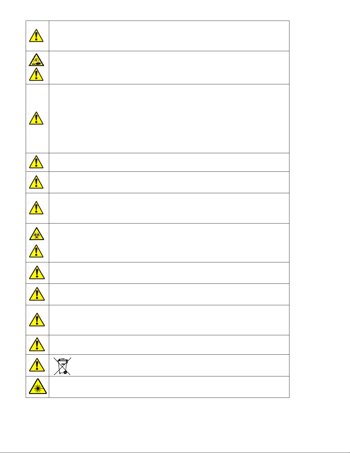
2.2 Special Symbols Used In This Manual
Label
Meaning
Explanation
Biohazard
Blood samples and analyzer waste are potentially infectious
materials.
Corrosive
Reagents may cause corrosion or skin irritation.
Warning
General warning of possible hazard conditions.
Sharp needle warning
The sampling needle may be a hazard to the operator.
2.3 General Precautions
The sampling needle and other components inside the analyzer may cause injury, or can
get damaged if handled incorrectly. Only certified personnel should open the covers.
Running measurements with opened cover is not recommended due to the risk of possible
injury. Always wear safety gloves while performing maintenance actions.
The analyzer weighs 35kg (~77lbs).Please do not attempt to move it alone. The analyzer
should always be moved by two persons holding the analyzer by its sides in an upright
position.
Always use safe lifting procedures when lifting the analyzer.
Make sure to retain the original packaging material for safe transportation and storage in
the future.
13
To prepare the analyzer for shipping, storage or extended periods of inactivity, please drain
the reagents and repackage the ‘Abacus 5’in its original packaging. Do not expose the
‘Abacus 5’to direct sunlight, extreme temperature or humidity (>80%).
The analyzer operates with chemically and biologically active reagents. Physical contact
with these reagents should be avoided. Please read reagent descriptions carefully for
possible emergency actions.
To ensure reliable operation and reliable results:
Only human blood samples should be analyzed
Only genuine Diatron reagents should be used
Required maintenance (user and service level) should be performed as
recommended in this manual
Only Diatron certified service personnel should perform service actions
Only genuine Diatron service materials and spare parts should be used
Genuine reagents and service materials and spare parts are available from Diatron.
Only Diatron certified service personnel that have successfully completed the ‘Diatron
Abacus 5 Service Training’ program are qualified to service the ‘Abacus 5’ analyzer.
Before operating the ‘Abacus 5’ analyzer, all operators should complete a ‘Diatron Abacus
5 Operator Training’ program. This program is offered by Diatron or by Diatron certified
service personnel.
Replacement materials or spare parts (tubes, valves, etc.) which might have been in
contact with human blood or reagents should be handled as a potentially biologically
hazardous and chemically dangerous material. All applicable laws and regulations must be
observed in the handling and disposal of these materials.
The ‘Abacus 5’ is designed for laboratory operation. Mobile operation is not supported.
Operate ‘Abacus 5’ within the ambient temperature range described in section 2.4.
The IVD equipment complies with the emission and immunity requirements described in
relevant part of the IEC 61326 series.
This equipment has been designed and tested to CISPR 11 Class A. In a domestic
environment it may cause radio interference, in which case, you may need to take
measures to mitigate the interference.
Electromagnetic environment should be evaluated prior to operation of the device.
This analyzer contains electronic components. Please handle electronic waste
adhering to local or federal regulations.
CAUTION –Use of controls or adjustments or perfomance of procedures other than those
specified herein may result hazardous radiation exposure.
14
2.4 Environmental Factors
Operate the ‘Abacus 5’analyzer within the ambient temperature range of 15-30°C (59-86 °F) and a relative humidity
range of 10% - 80%. The optimum operating temperature is 25°C (~77°F).
The ‘Abacus 5’ analyzer should be stored within the temperature range of 5-35°C (41-95 °F). Avoid exposing the
‘Abacus 5’ analyzer to direct sunlight or to extreme high or low temperatures. If the ‘Abacus 5’ analyzer was
subjected to extreme temperatures during shipment or storage, the analyzer must be placed for at least one hour in
a room whose temperature is within the operational range before installation or use.
Reagents should be stored at a temperature range of 15-30°C (59-86 °F). Reagents may experience a temperature
range of at most 5-35°C (41-95 °F) for a maximum of 3 days.
The analyzer should be placed in a well-ventilated location.
Operation at an altitude above 3000 meters (9800 ft) is not recommended.
2.5 Electrical Requirements
The analyzer should only be operated from a wall outlet meeting these power input requirements:
100-127VAC/200-240VAC; 47Hz to 63Hz
Power Consumption: maximum 400 VA
Please ensure that the wall outlet is also capable of supplying the power consumption of any additional devices (such
as a printer).
Use only the power cord supplied with the instrument. Avoid using extension cords. The ‘Abacus 5’analyzer comes
with a power cord appropriate for your power system. Proper use of the appropriate power cord assures adequate
grounding of the system. If the power is not reliable, contact your representative for options such as the installation
of an external UPS module.
Failure to properly ground the ‘Abacus 5’bypasses important safety features and may
result in electrical hazard.
The instrument should not be placed near potentially interfering devices capable of emitting radio frequencies (e.g.
radio or television transmitters/receivers, radars, centrifuges, X-ray devices, fans, etc.).
This analyzer is designed to be safe for transient voltages to INSTALLATION CATEGORY II and POLLUTION DEGREE 2.
2.6 Space Requirements
It is important to install the instrument in a suitable location. A poor location can adversely affect its performance.
Select a well-ventilated location near a power source and close to a suitable drain.
Place the unit on a clean, level surface. Leave at least 0.5 m (18 inches) space on both sides and above the instrument
to access pneumatics. A minimum of 0.2 m (8 inches) must be maintained between the rear panel and the wall to
allow for heat dissipation and tubing clearance.
Ensure there is enough clearance in front of the ‘Abacus 5’ analyzer to open the front panel. Allow enough space if
you want to use optional external keyboard, mouse or bar code reader.
Table of contents
Other Diatron Laboratory Equipment manuals


Popular Laboratory Equipment manuals by other brands

Woodley
Woodley Clinispin HCT II user manual

BRASSELER USA
BRASSELER USA Forza L50K Operation manual

Elektro-Automatik
Elektro-Automatik EL 9000 T Series operating manual

mesabiotech
mesabiotech Accula Dock Operator's guide

Buhler
Buhler EGK 2-19 Installation and operation instruction

Drawell
Drawell LBI-175A-N user manual


Milestone
Milestone R-Tracker Operator's manual

Metrohm
Metrohm 806 manual

SciCan
SciCan STATIM 5000S Operator's manual

Halma
Halma Ocean Insight FLAME-DA-CUV-UV-VIS Installation and operation instructions

Getinge
Getinge 8666 Service instructions
 Light Engine instruction manual")
Lumencor
Lumencor SPECTRA III (L) Light Engine instruction manual