Drawell LBI-175A-N User manual

1
User Manual
Please read operating manual before installation and operation.
Drawell International Technology Limited
Chongqing Drawell Instrument Co., Ltd.
Shanghai Drawell Scientific Instrument Co.,Ltd.
Chongqing Center : Suite 2705,Building No.12,Shiyou Road No.1, Yuzhong District,
Chongqing, China.
Shanghai Office : Suite 1117,Lane561 XiuChuan Rd.,PuDong New
Area,Shanghai,China
Homepage : www.drawell.com.cn
Tel : 0086-023-63268643
Email : sales05@drawell.com.cn

2
Contents
I:Precautions..........................................................................3
II:Application...........................................................................4
III. Technical Specifications....................................................4
IV: Instruction for controller.....................................................5
V.Wiring diagram ...................................................................7
VI. Printer Instruction...............................................................7
VII:USB Instruction..................................................................9
VIII:Transportation and storage.............................................15
IX:After-sales service.............................................................15
X:Failure handling methods...................................................15
XI: Packing List……………………………………….………….16

3
Thanks for purchasing the equipment, please carefully read the manual before operating.
I:Precautions
1) After the equipment is in place, lock the front casters to make the chamber stable.
2) To protect the compressor, pls turn on the instrument after 48 hours when placed.
3) Connect the 220V / 50Hz power supply, and the power socket should be reliably
grounded.
4) The device should be placed in a place that is protected from sunlight, cool and
ventilated. The distance between the device and the wall must be more than 10 cm.
Handle with care, the angle with the ground level should not be less than 45 °.
5) In order to maintain the good appearance of the equipment, pls do not wipe the
machine surface with acid or alkali or corrosive substances.The inside and outside of the
instrument can be regularly cleaned with dry cloth.
6) In order to obtain good working performance of the equipment, the difference
between the working temperature and the environment should not be too large, and the
ambient temperature should preferably be (20 ± 5) ℃.
7) Fuse is installed at the back of the control box for this equipment. If the equipment
is not powered, please check whether the fuse tube is intact. please cut off the power
before checking and replacing the fuse tube and replace the same type and
specifications!
8) Fans are installed in the operation room. Don’t insert your fingers or objects into
the fan cover to avoid safety accidents and damage to the fan .Please cut off the power
before changing the fan.
9) Stop using ,please turn off the power switch.
10) Do not store flammable or explosive materials or hazardous materials in the

4
instrument working room.
11) There is an overflow pipe on the back of this device. A small amount of water will
be discharged during use. Please use a leather pipe to connect to the container or the
sewer.
12) There is a drain pipe at the back of the device. When the device is not in use,
water is drained from the inside of the chamber.
II: Application
The biochemical incubator has temperature adjustment function. it’s widely used in
low temperature, constant temperature test for scientific research and production
departments such as environmental protection, medical treatment, health, epidemic
prevention, drug , agricultural,livestock and aquatic products, etc. It is the ideal instrument
for BOD analysis, bacteria culture, microorganisms, plant cultivation and breeding
III:Technical Specifications
Model
Temp.
Range(℃)
Display
Resolutio
n
Temp.
Fluctuatio
n
Temp.
Uniformity
Timin
g
Power
(KW)
Chamber
Size(W×D×H)c
m
Exterior
Size(W×D×H)c
m
LBI-175A-N
A:-20~65
B:-40~65
0.1℃
±0.5℃
±1℃
1~9999
min
0.7
45×42×93
61×71×167
LBI-275A-N
0.8
58×51×93.5
70×90×170
LBI-375A-N
1.0
59×55×116
75×86×190
LBI-475A-N
1.2
70×55×125
86×86×199
LBI-175B-N
0.7
45×42×93
61×62×150
LBI-275B-N
0.8
58×51×93.5
74×71×157
LBI-375B-N
1.0
59×55×116
75×75×173
LBI-475B-N
1.2
70×55×125
86×75×182

5
IV:Instruction for controller
1. Definition for display window
(1) : Cycle or segment value;
(2) : timing or time setting value;
(3) :temperature measurement value;
(4) Display window: temperature setting value;
(5) : humidity measurement value;
(6) : humidity setting value;
(7) : Illumination set value or heating output
2.Key definition
Lock
Under normal display, long press the key for 2
seconds to manually lock or unlock the screen.
Light
Under normal display, press the key to turn on the
light inside
Set
In the normal display, press the key to enter the
modification interface of setting value , long press
the key for 3 seconds to enter the parameter
modification interface.
Shift
In the setting state, press the key to make the
setting value shift and modify.
If running mode, can switch the display for
segments or cycle.
Increase
Press the key in the setting state to increase the
setting value.

6
3.Temperature setting
Press the set key and the temperature setting number in the (4) display window will flash,
can set the desired temperature by pressing the shift key, Increase key and decrease key.
4.Temperature parameter table
Parameter
indication
Parameter
name
Description for parameter function
Factory default
Lc
password
When "Lc = 103", you can view and
modify the parameter value.
0
TH
Upper
deviation
Over
temperature
alarm
If “Measured value> Set value +
TH”, upper deviation alarm will be
turned on and temperature output will
be turned off.
During the alarm, the temperature
alarm relay has output, the buzzer
beeps, the alarm indicator lights up,
the temperature unit flashes quickly,
click any key to cancel the beep, and
the relay turns off the output.
(0~20.0℃)
5.0
TL
Lower
deviation
Over
temperature
alarm
If "measured value <set value +
TL", there will be he lower deviation
alarm.
During the alarm, the temperature
alarm relay has an output, the buzzer
beeps, and the temperature unit
flashes slowly. Click any key to cancel
the beep.
Note: When "TL = 0", this function is
invalid.
(-50.0~0℃)
0
Tb
Deviation
correction
Correct the error caused by sensor
(low temperature) measurement;
Tb = actual temperature value-meter
measurement value.
(-99.9~99.9℃)
0
TA
Slope
correction
Correct the error caused by sensor
(high temperature) measurement;
TA = 1000 * (actual temperature
value-instrument measurement
value) ÷ instrument
measurement value.
(-999~999)
0
Decrease
Press the key in the setting state to decrease the
setting value.
Run/Stop
In the normal display state, press this key to start
or stop the operation

7
V: Wiring diagram
VI:Printer Instruction
1. Time display:in normal conditions,display the current time (hours and minutes)
2. OUT indicator: the light turned on, indicates that there is a printout or data is written to
the U disk;
3. COM indicator: flashing light indicates the current communication is normal;
4. USB indicator: the light turned on means that the current U disk has been correctly
inserted and data can be written;
5. Increase key: Under normal state, click or long press the key to increase the
printing interval time setting value.Under parameter setting state, click or long press the

8
key to increase the parameter setting value, when the time setting value is the
maximum,then press this key again will automatically flip to the minimum value;
6. Decrease key/OK key: Under normal state, click or long press the key to decrease
the setting value of printing interval time.Under parameter setting state, click this key to
switch the setting parameters, long press the key to exit the setting and save the set
value;
7. : Under normal status, long press two keys at the same time, after 3
seconds,enter the parameter setting state
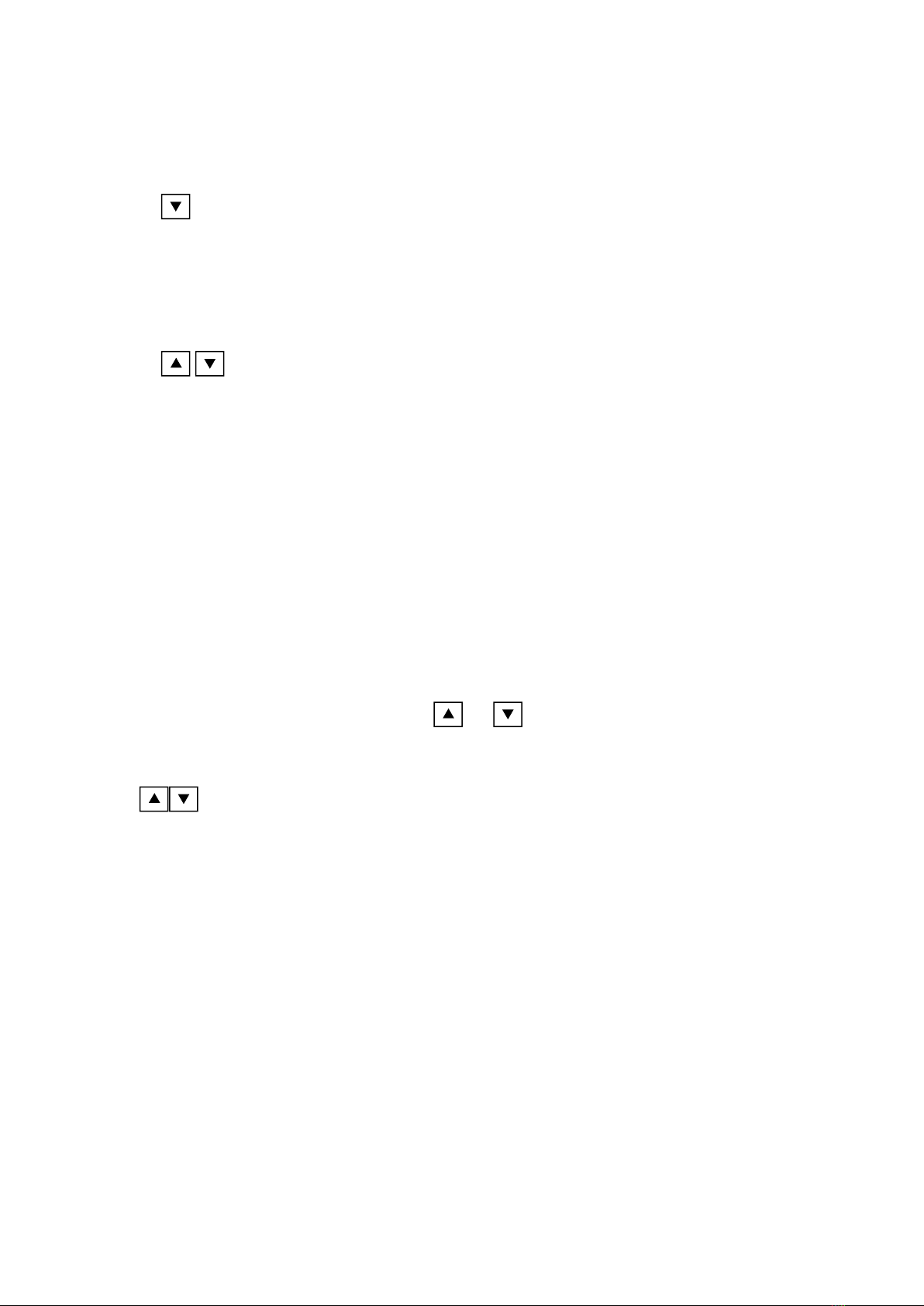
Operation for printer
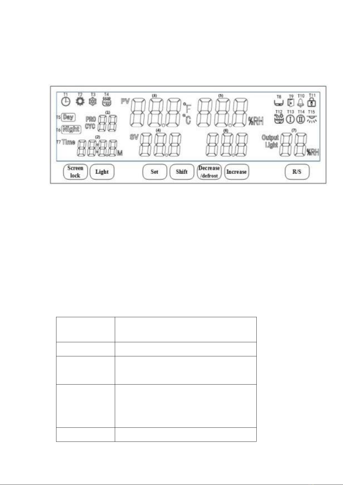
1)After powered on, the digital tube and the indicator light are all on for 3 seconds
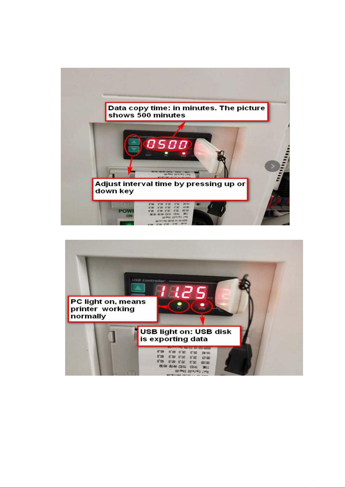
and then enter the running state. PRT indicator lights on, time window displays the
current time (hours and minutes), the printer prints "Print Test", "Current Date",
"Current Data" in sequence, the OUT indicator lights up when printing out. The data
is printed according to the printing interval. When the date changes, the date is
printed.
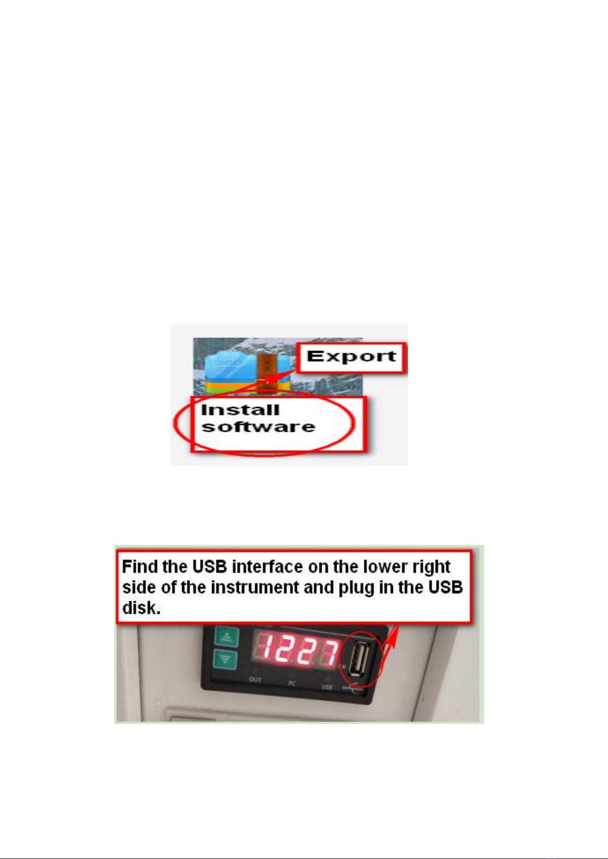
2) Under normal conditions, click or to set the printing interval. The
setting range is from 1 to 9999 minutes; in normal status, long press the button
for 3 seconds at the same time to enter the password input state, enter the
corresponding password to adjust the time and parameters.
Tips for abnormal phenomenon:
Time display shows TErr: communication error,
1) Check whether the instrument communication line is connected correctly;
2)Check whether the power of the instrument is turned on;
Time display shows UErr: U disk read and write error,
1)Check whether the U disk is inserted correctly;
2) Format the U disk or replace the U disk;
3) If don't need U disk storage, can enter the internal parameters to close the U disk

9
function;((if needed, pls contact supplier)
The time display shows PErr: the printer is wrong;
1)Check if the printer cable is connected correctly;
2) Check the indicator light on the printer, if it does not light, please confirm whether the
printer power cord is connected correctly;
3)If do not need the printing function, can enter the internal parameters to close the
printing function(if needed, pls contact supplier)
Printer indicator flashes: replace printing paper
VII:USB Instruction
Step 1: Install software
Step 2: Copy data
(1)Find the USB interface on the lower right side of the instrument and plug in the USB
disk.

10
(2)Adjust the interval time according to your experiment requirements.
(3)As picture shows: data exporting (printer and data export normal).

11
Step 3: Find and click the device monitoring system in program.
Step 4: Select device 1 and enter.

12
Step 5: Click to enter historical data.
Step 6: Click the external DAT file key (Insert the USB with data from instrument to the
computer before this operation ).
Step 7: Click on the desktop to find the computer and click to enter the computer.

13
Step 8: Find the USB disk with data and enter
Step 9: Find the copied data and click open to enter.

14
Step 10: After entering, it will show that XXX data has been successfully imported and
click ok to enter.
Step 11: Enter this step, you can see all the data you imported successfully and storage
status.

15
VIII:Transportation and storage
1.Care must be taken during transportation. The tilt should not exceed 45 ° and can not be
transported upside down. Handle it carefully.
2. Store in a relative humidity not exceeding 80%, non-corrosive gas and well-ventilated
room.
IX:After-sales service
The warranty for the instrument is 12 months from delivery (except for the heating
elements). If damaged due to non-human factors or can not work normally during
warranty period, our company is responsible for free repair or replacement of product
parts. Beyond the warranty, we try our best to provide convenience for users.
X:Failure handling methods
Problems
Reasons
Solution
No power supply
Socket without power
Change socket
Not plugged or wire broken
Plug well or connect wire well
Fuse is open
Change fuse
Power switch not on
Switch on.
The temperature inside
the box does not rise or
fall
Set temperature is incorrect
Adjust the set temperature
Temperature controller is broken
Change the temperature controller
Loose cable
Tighten the connection cable
Big deviation of
temperature in chamber
The sensor is broken
Replace the sensor
The fan is broken
Change the fan
The instrument is not corrected
Refer to the Instrument operation
instructions for correction
Note: Maintenance operations shall be carried out by qualified personnel. Please turn off
the power supply before repairing.

16
XI:Packing List
Item
Name
Category
Quantity
Remark
1
Biochemical incubator
Machine
1 set
2
Shelf(standard)
Accessories
3pcs
3
Instruction manual
Document
1pc
4
Fuse tube
spare parts
1pc
5
This packing list
Document
1 pc
We reserve the right to change the data in the manual without prior notice. The company
has the final interpretation right.
This manual suits for next models
7
Table of contents
Other Drawell Laboratory Equipment manuals

Drawell
Drawell TDD4-MC User manual

Drawell
Drawell B Series User manual

Drawell
Drawell DW-FD Sereries User manual

Drawell
Drawell GL10-MC Installation manual

Drawell
Drawell DW-GI Series User manual

Drawell
Drawell DW-280B 18L User manual

Drawell
Drawell TANK User manual

Drawell
Drawell DW-TDZ5-WS Installation manual

Drawell
Drawell Gentier 96E User manual

Drawell
Drawell DW-280D User manual