Dicon GP700M User manual

Artisan Technology Group is your source for quality
new and certied-used/pre-owned equipment
• FAST SHIPPING AND
DELIVERY
• TENS OF THOUSANDS OF
IN-STOCK ITEMS
• EQUIPMENT DEMOS
• HUNDREDS OF
MANUFACTURERS
SUPPORTED
• LEASING/MONTHLY
RENTALS
• ITAR CERTIFIED
SECURE ASSET SOLUTIONS
SERVICE CENTER REPAIRS
Experienced engineers and technicians on staff
at our full-service, in-house repair center
WE BUY USED EQUIPMENT
Sell your excess, underutilized, and idle used equipment
We also offer credit for buy-backs and trade-ins
www.artisantg.com/WeBuyEquipment
REMOTE INSPECTION
Remotely inspect equipment before purchasing with
our interactive website at www.instraview.com
LOOKING FOR MORE INFORMATION?
Visit us on the web at www.artisantg.com for more
information on price quotations, drivers, technical
specications, manuals, and documentation
Contact us: (888) 88-SOURCE | sales@artisantg.com | www.artisantg.com
SM
View
Instra

DiCon
FIISIROPTICS, INC
GP700M
Modular Platform
Supplement to the GP700 Operation Manual
91507 Revision A3 March 11, 2005

2DiCon Fiberoptics GP700M Modular Platform
Copyright © 2005 DiCon Fiberoptics, Inc.
All rights reserved. Printed in the United States of America.
This manual may not be reproduced in whole or in part, in any form or by any means,
without the express written permission of DiCon Fiberoptics, Inc. ("DiCon")
No Liability for Errors
DiCon reserves the right to correct technical and typographical errors in this manual at any
time, without prior notice. In no event shall DiCon be liable for errors in this manual or for
any damages arising out of, or relating to, this manual.
Product Warranty/Limitation of Remedies
DiCon warrants, to the original Buyer, all of its products to be free from defects in both
workmanship and material for a period of one year from the date of shipment. This
warranty extends to all products which have proved defective through normal use, but
excludes products that have been damaged, mishandled, disassembled, modified, or
misused by Buyer or any other person. This warranty is in lieu of all other warranties, and
DiCon disclaims all other warranties express or implied, including any warranty of
merchantability, fitness for a particular purpose, or arising from the course of dealing
between the parties or usage of trade. DiCon does not extend any warranty of any kind
whatsoever to any purchaser of the products from Buyer or to any end-user of the products.
DiCon, at its sole choosing, will replace or repair to proper working condition any products
under warranty that are returned. Products repaired or replaced under warranty are only
warranted for the remaining unexpired period of time of the original warranty. DiCon
reserves the right to issue a credit memo for any defective product as an alternative to
product replacement or repair. DiCon will not accept Buyer generated debit memos. Buyer
may not setoff or withhold payment because any product is defective. In no event shall
DiCon's liability under this warranty and this contract exceed the purchase price of the
products. In no event shall DiCon be liable under this warranty or this contract for
consequential, incidental or special damages.
Return Material Authorization Terms
DiCon will only accept a return of products for which a DiCon Return Material Authorization
("RMA") Number has been issued to Buyer prior to the shipment of the return products to
DiCon. This RMA Number must be displayed on all return shipment documents. DiCon will
refuse all returns that are not accompanied by an RMA Number. All risks of any such
refused shipment are the sole responsibility of Buyer.
For warranty returns, DiCon will only accept return products accompanied by a statement
of defects. DiCon will not evaluate returns not including this information, and such returns
will be returned to Buyer at Buyer's expense.
Warranty returns proved defective through damage, mishandling, disassembly,
modification, or misuse by Buyer or any other person, and warranty returns found non-
defective, will be subject to evaluation and processing fees, and repair costs if applicable.
Non-warranty returns will be evaluated and will be subject to evaluation and processing
fees. If non-warranty repair work is necessary, Buyer will be notified of repair costs before
arepair work order is initiated. Confirming POs are required for non-warranty repair work.
For warranty returns, Buyer is responsible for one-way freight costs to DiCon, including any
duty and taxes. DiCon will cover freight costs for return shipment to Buyer. Shipment
charges billed to DiCon without prior approval from DiCon will be re-invoiced to Buyer.
91507 Revision A3 March 11, 200;

3
For non-warranty returns, Buyer is responsible for two-way freight costs, including any duty
and taxes. If shipment consists of returns that are both warranty and non-warranty, the
shipment will be considered as non-warranty.
DiCon will not accept Buyer generated debit memos.
All international return shipments to DiCon, including packaging and airway bill, must be
marked "Goods made in the United States; enter as American Goods Returned ('AGR')"
and state the reason for the return to the United States. DiCon will refuse all returns that are
not properly documented. All risks of any such refused shipment are the sole responsibility
of Buyer.
International returns should be sent via Federal Express, UPS or DHL. International
returns may be processed using DiCon's brokerage: EWI Inc. 305 Harbor Way, South San
Francisco, CA 94080. Contact Harvey Louis at TEL: (650)794-1388, FAX: (650)794-1389.
If one of these carriers or DiCon's broker is not used, DiCon may invoice Buyer for any
additional costs including duty and taxes.
Reverse Engineering / Confidentiality
Buyer shall not reverse engineer, decompile, disassemble, modify, reproduce or copy any
products or any software within any products. Buyer shall not analyze or identify the
chemical composition or the physical characteristics of any products. Buyer shall not
furnish DiCon specifications to any other person
Software License
DiCon does not transfer ownership of software contained in any products. DiCon grants to
Buyer a perpetual non-exclusive license to use software in the operation of the product in
which it is contained. This license is transferable only with the transfer of ownership of the
product.
91507 Revision A3 March11,2005

4DiCon Fiberoptics GP700M Modular Platform
About This Manual 5
Product Overview 5
The Plug-In Configuration Menu 6
Adding a Plug-In 7
Deleting a Plug-In 9
Supplemental Instructions for GP700M with
Two-Position Prism Switch Plug-In 11
Clearing All Plug-Ins 14
Troubleshooting 15
Device Housing 16
Handling Fiberoptic Components and Cables 18
Handling Fiberoptic Cables 18
Storing Optical Connectors 18
Cleaning Optical Connectors 19
Mating Optical Connectors 19
Contents
,91507 Revision A3 March 11, 2005

About This Manual 5
•
About This Manual
This manual, the GP700M Modular Platform Operation Manual, assumes basic familiarity
with the GP700 interface. The GP700M Manual is intended as a supplement to the GP700
Programmable Flberoptic Instrument Operation Manual (doc. #91506).
The GP700 Manual describes how to control the GP700 and GP700M using the front panel
keypad, mini-programs, the RS-232 interface, and the GPIB interface. In addition, the
GP700 Manual gives optical and electrical specifications. If you are new to the GP700, you
should first familiarize yourself with the instrument and interface by reading the GP700
Manual.
The GP700M Manual describes the unique features of the GP700M, and provides instruc-
tions for adding and deleting plug-ins. Once installed, plug-in components behave exactly
the same as permanent non-modular components. Refer to the GP700 Manual for informa-
tion about controlling installed plug-ins and other components.
Product Overview
DiCon's GP700M Modular Platform builds on the flexibility of DiCon's GP700 Programma-
ble Platform by adding modular plug-in capability. The GP700M shares the GP700's pow-
erful user interface at the same time it offers convenient and fast installation of fiberoptic
switches, tunable filters, and variable attenuators.
The GP700M can accommodate four or eight modular plug-ins, depending on the configu-
ration purchased. Additionally, the instrument can be configured with non-modular internal
components by request. The following diagrams show the four-plug-in and eight-plug-in
chassis options.
Figure 1: GP700M With Four Plug-In Bays (Top View)
5XLa
-CIF Ecuct,l:
jv Srtuvitc
EXFAV=5;t:iti 1.:4Fe."4:...AY AND
VPC.:; MCT HT, Pa-DAR:
-E-OMFONE1‘4-S
91507 Revision A3 March 11, 2005

6DiCon Fiberoptics GP700M Modular Platform
Figure 2: GP700M With Eight Plug-In Bays (Top View)
P5WE X;;•7.11Siati at%
L. CM,11F
1(;)$1
The Plug-In Configuration Menu
.heRmionoov.
[...-,Lvipr:Ai,N
Press the PCFG softkey to open the plug-in configuration menu. You may have to press
MORE a few times in order to see the PCFG key. The plug-in configuration menu offers
three options:
•Use ADDP to add a plug-in.
•Use DELP to delete a plug-in.
•Use CLRP to clear all plug-ins.
Depending on the status of the currently selected component, the bottom line will display
one of two messages. If the currently selected device is not a plug-in module, the bottom
line will display "NOT A PLUG-IN". The following diagram shows the plug-in configuration
menu of a GP700M configured with several components. The currently selected compo-
nent, M2, is a permanent non-modular component.
Figure 3: Plug-in Configuration Menu Screen, Permanent Component Selected
0
0
/
S1
2
3
NOT A PLUG-IN
ADDP
DELP
CLRP
91507 Revision A3 March 11, 2005

The Plug-In Configuration Menu 7
If the currently selected device is a plug-in module, the bottom line will display "DELETE
WITH DELP". The following diagram shows the plug-in configuration menu of a GP700M
configured with a tunable-filter plug-in. The plug-in is the currently selected component.
Figure 4: Plug-in Configuration Menu Screen, Plug-in Selected
F11563.01 ADDP
DELP
CLRP
DELETE WITH DELP
Adding a Plug-In
Adding a plug-in alters the configuration of both the plug-in and the GP700M instrument.
For this reason, a plug-in that has been added to one instrument cannot be added to a sec-
ond instrument until it has been deleted from the first instrument using the DELP com-
mand, or cleared using the CLRP command. See below for information about these
commands.
To add a new plug-in, open the plug-in configuration menu by pressing the PCFG softkey.
Then press ADDP to begin the add plug-in procedure. The GP700M will display an instruc-
tion dialog screen that gives you the option to continue or to exit.
Figure 5: Add Plug-In Instruction Dialog
Slide just one plug-
in module into rear
expansion slot.
ENTER to add.
ESC to stop.
HELP twice to exit.
If you do not wish to add a plug-in, press ESC once or HELP twice. Both operations will
perform a system reset and return you to the main menu.
To install a plug-in, locate a vacant slot in the rear of the instrument. Remove the blank
cover panel by loosening the top and bottom captured thumb screws. Stop loosening when
the screws spring out. Hold the plug-in so that the printed text and logo are upright legible,
taking care not to touch the recessed electrical connector on the opposite side.
Slide the plug-in cartridge into a vacant slot in the rear of the instrument. Each plug-in has
top and bottom flanges that slide into rails installed in the housing. The plug-in should slide
easily. Do not force the plug-in, as this could cause damage to the plug-in, the instrument,
or both.
When you have inserted the plug-in almost completely, you will feel some resistance as the
plug-in comes into contact with the backplane. Press firmly to establish a proper connec-
tion. The plug-in's external panel should now be flush with the fixed rear electrical panel.
Tighten the thumb screws to secure the plug-in.
91507 Revision A3 March 11, 2005
8DiCon Fiberoptics GP700M Modular Platform
..„. „„
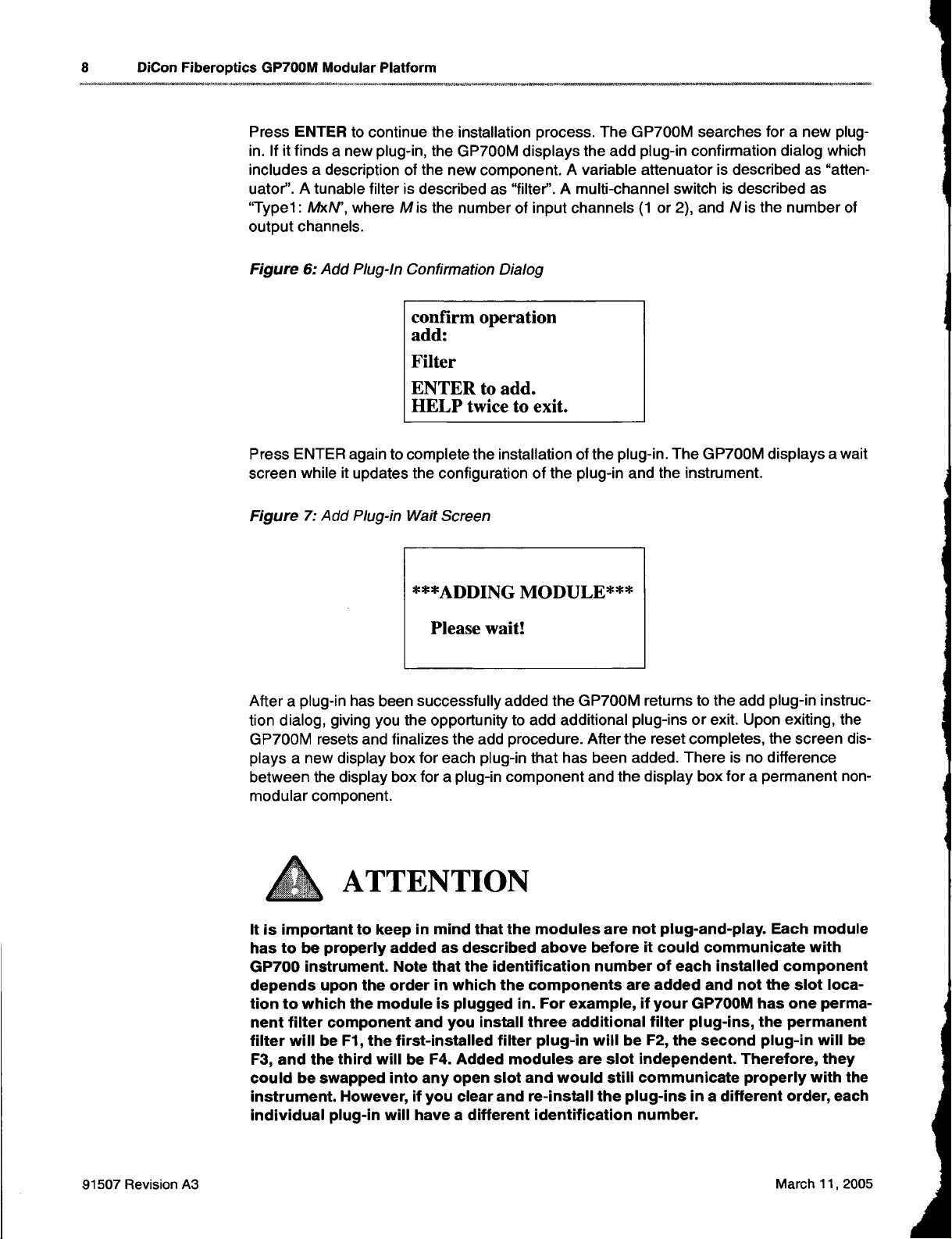
Press ENTER to continue the installation process. The GP700M searches for a new plug-
in. If it finds a new plug-in, the GP700M displays the add plug-in confirmation dialog which
includes a description of the new component. A variable attenuator is described as "atten-
uator". A tunable filter is described as "filter". A multi-channel switch is described as
"Typel : MxN', where M is the number of input channels (1 or 2), and N is the number of
output channels.
Figure 6: Add Plug-In Confirmation Dialog
confirm operation
add:
Filter
ENTER to add.
HELP twice to exit.
Press ENTER again to complete the installation of the plug-in. The GP700M displays a wait
screen while it updates the configuration of the plug-in and the instrument.
Figure 7: Add Plug-in Wait Screen
***ADDING MODULE***
Please wait!
After a plug-in has been successfully added the GP700M returns to the add plug-in instruc-
tion dialog, giving you the opportunity to add additional plug-ins or exit. Upon exiting, the
GP700M resets and finalizes the add procedure. After the reset completes, the screen dis-
plays a new display box for each plug-in that has been added. There is no difference
between the display box for a plug-in component and the display box for a permanent non-
modular component.
ATTENTION
It is important to keep in mind that the modules are not plug-and-play. Each module
has to be properly added as described above before it could communicate with
GP700 instrument. Note that the identification number of each installed component
depends upon the order in which the components are added and not the slot loca-
tion to which the module is plugged in. For example, if your GP700M has one perma-
nent filter component and you install three additional filter plug-ins, the permanent
filter will be Fl, the first-installed filter plug-in will be F2, the second plug-in will be
F3, and the third will be F4. Added modules are slot independent. Therefore, they
could be swapped into any open slot and would still communicate properly with the
instrument. However, if you clear and re-install the plug-ins in a different order, each
individual plug-in will have a different identification number.
91507 Revision A3 March 11, 2005

The Plug-In Configuration Menu 9
Deleting a Plug-In
Deleting a plug-in erases record of the plug-in from the GP700M controller configuration,
and clears the plug-in configuration record. It is necessary to delete a plug-in or clear all
plug-ins (see below) before re-installing in another chassis.
To delete a plug-in, open the plug-in configuration menu by pressing the PCFG softkey.
Next, activate the component you wish to delete by pressing the (n, DEV, PREV, and
NEXT keys. The 1Z) key toggles the display screen; the DEV key selects the component
category; the PREV and NEXT keys select a particular component within a component cat-
egory.
The bottom line on the front-panel display will show "NOT A PLUG-IN" if the currently acti-
vated component is not a plug-in module. When you activate a plug-in component, the dis-
play will show "DELETE WITH DELP".
When you have activated the plug-in you wish to delete, press DELP to begin the delete
plug-in procedure. The GP700M will display an confirmation dialog screen prompting you
to press ENTER to confirm or HELP twice to exit without deleting.
Figure 8: Delete Plug-in Confirmation Screen
*** WARNING!!! ***
Plug-in module
will be deleted if
ENTER is pressed!
HELP twice to exit.
Choosing to exit causes the GP700M to reset without deleting the plug-in. Pressing
ENTER causes the GP700M to update the controller and plug-in configuration records.
The GP700M displays a wait screen during the deletion process, then the instrument
resets.
Figure 9: Delete Plug-in Wait Screen
***DELETING NOW***
Please wait!
91507 Revision A3 March 11, 2005

10 DiCon Fiberoptics GP700M Modular Platform
Remove the plug-in from the chassis by loosening the captured thumb screws. Stop loos-
ening when the screws spring out. Next, pull gently but firmly on the loosened screws. You
will feel some resistance as the plug-in disengages from the backplane. Once free of the
backplane, the plug-in should slide easily. Do not force the plug-in, as this could cause
damage to the plug-in, the instrument, or both.
When you remove the plug-in from the chassis, take care not to touch the plug-in's
recessed electrical PCB. Cover the empty slot in the chassis with a blank cover panel to
minimize dust contamination.
Warning
Do not leave deleted plug-ins connected to the controller backplane as this could result
in functional errors.
91507 Revision A3 March 11, 2005

The Plug-In Configuration Menu 11
P1 RCL1 2 3 4 .
2SAVE
1 2 3 4
3PROG
12 n n
>P1: 9 MORE
Supplemental Instructions For GP700 Modular With Two-Position
Prism Switch Plug-In
This section describes the operating instructions and NEW command set required for
any GP700M Modular Mainframe containing the Two-Position (Prism) Switch Plug-Ins.
WARNING
Do not install the Two-Position Switch Plug-In into GP700 Mainframes without a
triangular "Prism Ready label on the rear or with firmware version lower then Vesion
2.12. The Two-Position Switch Plug-In is identified by a P/N starting with "PS-" which is
marked on the lower section of the connector faceplate. This device will NOT function
with any earlier version of the firmware. The firmware version is shown on the front
panel display upon power up. Contact DiCon if you wish to use this Plug-In in a GP700
Mainframe that does not fit this description.
FRONT PANEL OPERATION
a. Add/Delete
User can use the PCFG softkey to add/delete Pwo-Position PlugIns. The
procedure is identical to any other modular Plug In. It will display the current
module configuration when user adds in the module and allow the user to
accept it.
b. Display and Moving Switches
The Two-Position Plug Ins are always displayed on the last page of the screen,
depending on if there are other types of Plug-Ins, the 'Next Page' button may
need to pressed several times to display the Two-Position Plug-Ins. The 'Next
Page' button is represented by two overlapping boxes located directly above
the PREV button.
The front panel will show a row four small boxes for each Plug In module. Each
small box stands for one switch, starting from 1 to 4. It will show "n" in the box
where there is no switch.
When the small box is not highlighted, the switch is in state 1, when the box is
highlighted the switch is set to state 2. The figure below indicates that switch
number 4 in Plug-In number 1 is in State 2.
91507 Revision A3 March 11, 2005

12 DiCon Fiberoptics GP700M Modular Platform
Bit Map Channel Value Switch 1 Switch2 Switch3 Switch4
0000 1State 1 State 1 State 1 State 1
0001 2State 2 State 1 State 1 State 1
0010 3State 1 State 2 State 1 State 1
0011 4State 2 State 2 State 1 State 1
0100 5State 1 State 1 State 2 State 1
0101 6State 2 State 1 State 2 State 1
0110 7State 1 State 2 State 2 State 1
0111 8State 2 State 2 State 2 State 1
1000 9State 1 State 1 State 1 State 2
1001 10 State 2 State 1 State 1 State 2
1010 11 State 1 State 2 State 1 State 2
1011. 12 State 2 State 2 State 1 State 2
1100 13 State 1 State 1 State 2 State 2
1101 14 State 2 State 1 State 2 State 2
1110 15 State 1 State 2 State 2 State 2
1111 16 State 2 State 2 State 2 State 2
P1 RCL
1 2 34.
2SAVE
123 4
3PROG
12n n
>P1(S4): 2MORE
Pressing the PREV and NEXT key will change the active selection Vertically
on the screen (between P1, P2, P3, etc.)
The DEV key changes the active selection Horizontally on the screen
Pressing the DEV key repeatedly will 'step' though modes one and mode two
as described below
Mode one appears as >P2: 9 the numeric value 9 represents the Channel
Value, shown in bold italics in the table below.
This mode allows the user to move all switches contained in the Plug-In
simultaneously for time saving advantages.
Mode Two appears as >P1 (S4): 2 the numeric value 2 means switch
number 4 in Plug in number 1 is in State gas shown below.
In Mode Two the user can either press number 1 or 2 then the ENTER key or
use the Up/Down arrow key to toggle the switch between state 1 and state 2.
a. Mini-Program/Recall
The Mini program and recall is same as other modules.
91507 Revision A3 March 11, 2005

The Plug-In Configuration Menu 13
REMOTE COMMAND DEFINITIONS
Pn m
Select P-Type Module Channel
Application: GPIB, RS-232, MINI
Format: P<module> <channel>
Description: The P command sets prism switch module number module to channel
number channel. Do not send switching commands to busy modules.
Example: The following Visual Basic command sets prism switch module P1 to
channel 8 and P2 to channel 3.
CALL Send(0, 3, "P1 8; P2 3", NLend)
See Also: SYSTem:CONFig?, page 74 "Command Timing", page 39
Pn?
P-Type Module Channel Query
Application: GPIB, RS-232
Format: P<module>?
Description: The P? command places the current channel of prism switch module
number module into the output queue.
Example: The following Visual Basic command places the current channel of prism
switch module P1 into the output queue, and reads the output queue into buffer$.
CALL Send(0, 3, "P1?", NLend)
CALL Receive(0, 3, buffer$, NLend)
INCPn
Increment P-Type Module Channel
Application: GPIB, RS-232, MINI
Format: INCP<module>
Description: The INCP command increments prism switch module number module
by one channel. Do not send switching commands to busy modules.
Example: The following Visual Basic command increments prism switch module P2
by one channel.
CALL Send(0, 3, "INCP2", NLend)
See Also: "Command Timing", page 39
DECPn
Decrement P-Type Module Channel
Application: GPIB, RS-232, MINI
Format: DECP<module>
Description: The DECP command decrements prism switch module number module
by one channel. Do not send switching commands to busy modules.
Example: The following Visual Basic command decrements prism switch module P2
by one channel.
CALL Send(0, 3, "DECP2", NLend)
See Also: "Command Timing", page 39
91507 Revision A3 March 11, 2005

14 DiCon Fiberoptics GP700M Modular Platform
/,•...............
Clearing All Plug-Ins
Clearing all plug-ins erases all plug-in records from the GP700M controller configuration,
and clears the configuration record within each connected plug-in. It is necessary to delete
aplug-in (see above) or clear all plug-ins before re-installing in another chassis.
To clear all plug-ins, open the plug-in configuration menu by pressing the PCFG softkey.
press CLRP to begin the clear plug-ins procedure. The GP700M will display an confirma-
tion dialog screen prompting you to press ENTER to confirm or HELP twice to exit without
clearing.
Figure 10: Clear Plug-in Dialog Screen
*** WARNING!!! ***
All plug-in modules
will be deleted if
ENTER is pressed!
HELP twice to exit.
Choosing to exit causes the GP700M to reset without clearing the plug-ins. Pressing
ENTER causes the GP700M to update the controller and plug-in configuration records.
The GP700M displays a wait screen during the clear plug-in process, then the instrument
resets.
Remove each plug-in from the chassis by loosening the captured thumb screws. Stop loos-
ening when the screws spring out. Next, pull gently but firmly on the loosened screws. You
will feel some resistance as the plug-in disengages from the backplane. Once free of the
backplane, the plug-in should slide easily. Do not force the plug-in, as this could cause
damage to the plug-in, the instrument, or both.
When you remove the plug-in from the chassis, take care not to touch the plug-in's
recessed electrical PCB. Cover the empty slots in the chassis with blank cover panels to
minimize dust contamination.
Warning
Do not leave cleared plug-ins connected to the controller backplane as this could result
in functional errors.
91507 Revision A3 March 11, 2005

Troubleshooting 15
...fioNAeneermove,.........teranorso.
Troubleshooting
The add plug-in command only works if there is one new, cleared, or deleted plug-in
inserted into the GP700. If there are two or more new plug-ins inserted when you begin the
add procedure, the attempt will usually fail and give an error message. It is possible the add
procedure will appear to work, but will not complete successfully. In this case, when you
exit the add procedure and reset the instrument, the screen will not show a display box for
the new devices.
Although the plug-ins were not added successfully, the GP700M may have created errors
in the configuration records in the GP700M as well as in each of the plug-ins. To correct a
multiple add error, execute the clear plug-in command (CLRP) and re-install the plug-ins
one at a time.
Figure 11: Add Plug-in Error Screen
Operation failed!
ENTER to try again.
ESC to stop.
HELP twice to exit.
Attempting to add a plug-in without inserting the physical cartridge will also result in an
"operation failed" error. Insert a plug-in and press ENTER to try again.
91507 Revision A3 March 11, 2005

16 DiCon Fiberoptics GP700M Modular Platform
Device Housing
Figure 12: GP700M Modular Platform 4U Standard Rackmount Chassis
Front View
Rear View
FIXED P,EAR. t L
YOU rvAPotS
COMPONENTS
10
Side View
Note: 4U extended rackmount chassis differs only in depth (554mm).
91507 Revision A3 March 11, 2005

Device Housing 17
0M.V.M400.4.0.,
Figure 13: GP700M Modular Platform 6U Standard Rackmount Chassis
Front View
7.5 x 10
.:- FULL Ft
140
Rear View clxu) EA.L1FANEL.
Side View
•..:"7'7(':_,471
a".7,'"•••• CA MN
U
AtAPICO
04TERP-4,41.COMPONEUTE,
4
265:9
190.,
13 4
0
91507 Revision A3 March 11, 2005

18 DICon Fiberoptics GP700M Modular Platform
..... •••••
Handling Fiberoptic Components and Cables
Fiber optic components require special handling. Follow these guidelines when
handling the cables and connectors.
Handling Fiber Optic Cables
To avoid cable damage and to minimize optical loss, follow these guidelines when
handling fiber optic cables.
•Handle the fiber pigtail outputs carefully.
•The minimum bend radius for most optical cables is 35mm. Never bend an
optical cable more sharply than this specification. Optical performance will
degrade, and the cable might break.
•Avoid bending the optical cable near a cable strain relief boot. Bending an
optical cable near a strain relief boot is one of the easiest ways to permanently
damage the optical fiber.
•Avoid bending the optical cable over a sharp edge.
•Avoid using cable tie wraps to hold optical cable. Tie wraps when tightened can
create micro-bends or break an optical cable. Microbends can cause a dramatic
reduction in optical performance.
•Do not pull on the bare fiber as this can break the fiber inside the component.
•Avoid using soldering irons near optical cables. Accidental damage can easily
occur when a soldering iron is used near an optical cable. In addition, solder
splatter can contaminate and permanently damage optical fiber connectors.
•To assure the most stable, repeatable optical performance after the optical
cables have been connected, immobilize the cables using wide pieces of tape or
another form of mechanical cushion.
Storing Optical Connectors
All switches that include optical connectors are shipped with dust caps covering
those optical connectors. Optical connectors should remain covered at all times
when the instrument is not in use.
91507 Revision A3 March 11, 2005

Handling Fiberoptic Components and Cables 19
Do not bend the fibers at the
exit of the connector strain
relief boot. The fiber will
break if stressed at this point.
FIBEROPTIC
COMPONENT
CONNECTOR
FIBER
PIGTAILS
Do not bend the fibers at the
exits of the switch housing.
The fiber will break if
stressed at these points.
Figure 13: Fiber-Optic Component, Connectors, and Fiber Pigtails
Cleaning Optical Connectors
Clean any exposed connector using a cleaning kit supplied by the connector
manufacturer or high-grade isopropyl alcohol and a cotton swab. To clean with
alcohol and a swab, dab the tip of a cotton swab in alcohol and then shake off any
excess alcohol. The tip should be moist, not dripping wet. Stroke the swab tip
gently across the surface of the connector and around the connector ferrule.
Either allow the connector a minute to dry, or blow-dry the connector using
compressed air. Be careful when using compressed air: improper use may deposit
a spray residue on the connector.
Mating Optical Connectors
Follow these instructions when mating optical connectors.
•Clean both connectors prior to mating. Any small particles trapped during the
mating process can permanently damage the connector.
•Smoothly insert the appropriate connector ferrule into the adapter. Do not allow
the fiber tip to contact any surface. If the tip accidentally contacts a surface
before mating, stop. Reclean the connector and try again.
•Tighten the connector until it is finger tight or to the torque specified by the
connector manufacturer. Do not over-tighten the connector as this can lead to
optical loss and connector damage.
•Check the optical insertion loss. If the loss is unacceptable, remove the
connector, reclean both ends of the mate, and reconnect them. You have to
repeat this process several times before a low-loss connection is made.
•After you make the connection, monitor the stability of the optical throughput for
a few minutes. Optical power trending (slowly increasing or decreasing) is
caused by the slow evaporation of alcohol trapped in the connector. Continue to
monitor optical power until it stabilizes. If the loss is unacceptable, reclean the
connectors and start again.
91507 Revision A3 March 11, 2005
Table of contents


