DIEBOLD NIXDORF DN Series User manual

DN Series™ Check Deposit Module
Operator Manual
01750333061 A

Legal Disclaimer
Copyright © Diebold Nixdorf. Copyright protection is claimed for each revision listed in the document his-
tory, as of the date indicated. All Rights Reserved.
This document contains proprietary information of Diebold Nixdorf, Incorporated or its subsidiaries (col-
lectively “Diebold Nixdorf”) and may include information that is protected by copyright, trademark and
patent laws in the US, Germany, and globally. All rights, including rights created by patent grants or reg-
istration of a utility model or design, are reserved.
•No part of this document may be translated, reproduced, stored in a retrieval system, or trans-
mitted, in any form or by any means: electronic, mechanical, photocopying, recording, or oth-
erwise, without prior written permission from Diebold Nixdorf. Any violations of the foregoing
may give rise to a claim for damages.
•If the document pages state the information is confidential (or words of similar import), then
this document is intended solely for the use of the employees or other personnel of Diebold
Nixdorf unless expressly authorized in writing by Diebold Nixdorf. Other uses of this informa-
tion without the express written consent of Diebold Nixdorf are prohibited.
•This document should be treated as confidential material for security reasons. Any unautho-
rized disclosure or use of confidential material may violate the U.S. Theft of Trade Secrets
provisions of Section 1832 of Title 18 of the United States Code as well as comparable laws in
other jurisdictions throughout the world, and may be punishable by fine and imprisonment.
This document and the information contained herein are provided AS IS AND WITHOUT WAR-
RANTY. In no event shall Diebold Nixdorf or its suppliers be liable for any special, indirect, or
consequential damages of any nature resulting from the use of information in this manual. The in-
formation contained in this document is subject to change without notice. When using the document for
system implementation, please call your authorized Diebold Nixdorf sales or service representative for
any applicable changes.
Any trademarks, service marks, product names or company names not owned by Diebold Nixdorf, that
appear in this document are used for informational purposes only, and Diebold Nixdorf claims no rights
thereto, nor does such use indicate any affiliation with or any endorsement of Diebold Nixdorf or Diebold
Nixdorf products by the owners thereof.
Your use of this document and/or any of the information contained herein constitutes your agreement to
all of the terms stated on this page.
Copyright 2019 Diebold Nixdorf
01750333061 A
ii

Table of Contents
1 Introduction ................................................................................................................................ 1-1
1.1 Introduction ........................................................................................................................1-1
1.2 Information in this Manual ..................................................................................................1-2
1.3 Safety Precautions .............................................................................................................1-2
1.4 Signs, Labels and Symbols................................................................................................1-4
2 General safety instructions for the component ...................................................................... 2-1
3 Maintenance ............................................................................................................................... 3-1
3.1 Prerequisite Information .....................................................................................................3-1
3.2 Maintenance Procedures ...................................................................................................3-1
3.2.1 Checking the Print Quality .................................................................................. 3-2
3.2.2 Clearing a Jam.................................................................................................... 3-4
3.2.3 Inkjet Printer Cartridge ........................................................................................ 3-13
3.3 Beep Codes for Error Conditions .......................................................................................3-15
4 Supplies ...................................................................................................................................... 4-1
List of Figures
Figure 1-1 DN ™Series Check Deposit Module (Bin Side) ....................................................... 1-1
Figure 1-2 DN Series™ Check Deposit Module (PBCA Side)................................................... 1-2
Figure 3-1 Storage Bin............................................................................................................... 3-3
Figure 3-2 Green Tab for the Exception Bin.............................................................................. 3-5
Figure 3-3 Input/Output Assembly............................................................................................. 3-6
Figure 3-4 Open the Escrow Turn ............................................................................................. 3-7
Figure 3-5 Escrow Assembly ..................................................................................................... 3-9
Figure 3-6 Positions of the Escrow Assembly Kickstand........................................................... 3-10
Figure 3-7 Center and Deskew (CDS) Assembly Raised .......................................................... 3-11
Figure 3-8 Empty Escrow Roll Button........................................................................................ 3-12
Figure 3-9 Inkjet Printer Cartridge ............................................................................................. 3-13
List of Tables
Table 1-1 Warning signs used.................................................................................................. 1-4
Table 1-2 Used mandatory signs.............................................................................................. 1-4
Table 3-1 Dimensions of the Document ................................................................................... 3-1
Table 3-2 Bin Capacity ............................................................................................................. 3-1
Table 3-3 Recognized Fonts .................................................................................................... 3-1
Table 3-4 Beep Codes for Error Conditions ............................................................................. 3-15
Copyright 2019 Diebold Nixdorf
01750333061 A
iii
1
1 Introduction
1.1
1.1 Introduction
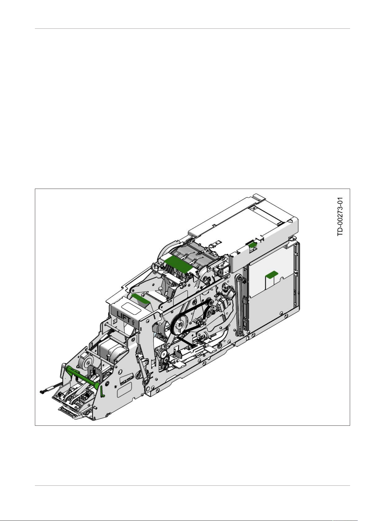
The DN Series™ check deposit module (Figure1-1 and Figure1-2) accepts a stack of up to 30 docu-
ments and provides MICR data and image of each document to the banking network. Documents can be
inserted face up or face down, with the short edge first.
When the transaction has been completed, the module can print up to 80 characters on the document.
• If the document was inserted face up, the printing will be on the back of the document.
• If the document was inserted face down, the printing will be on the front of the document.
The documents are then deposited into the storage bin or the exception bin.
• The storage bin is designed to hold up to 600 documents.
• The exception bin holds up to 30 documents.
Figure1-1: DN ™Series Check Deposit Module (Bin Side)
Copyright 2019 Diebold Nixdorf
01750333061 A
1-1
Introduction
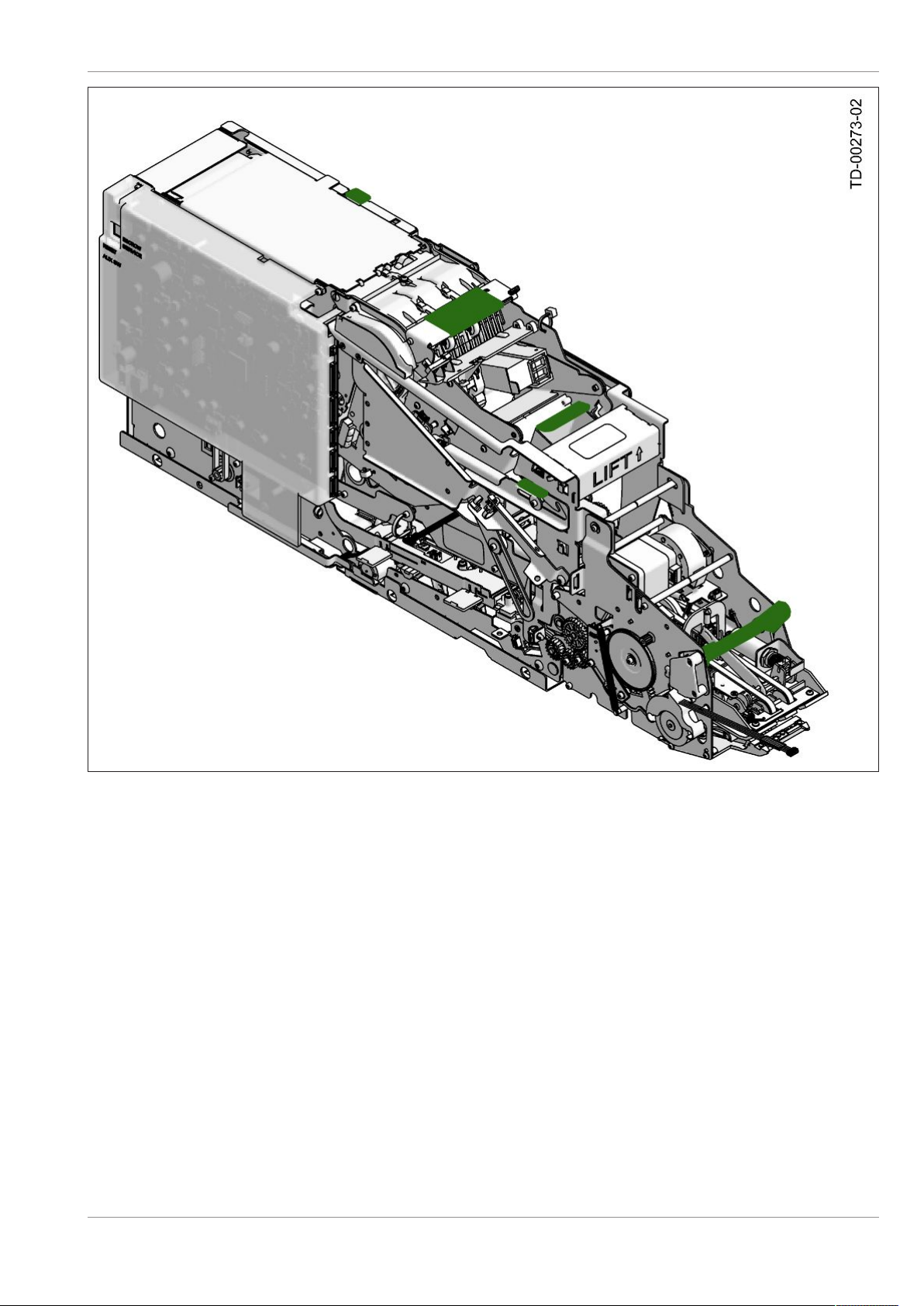
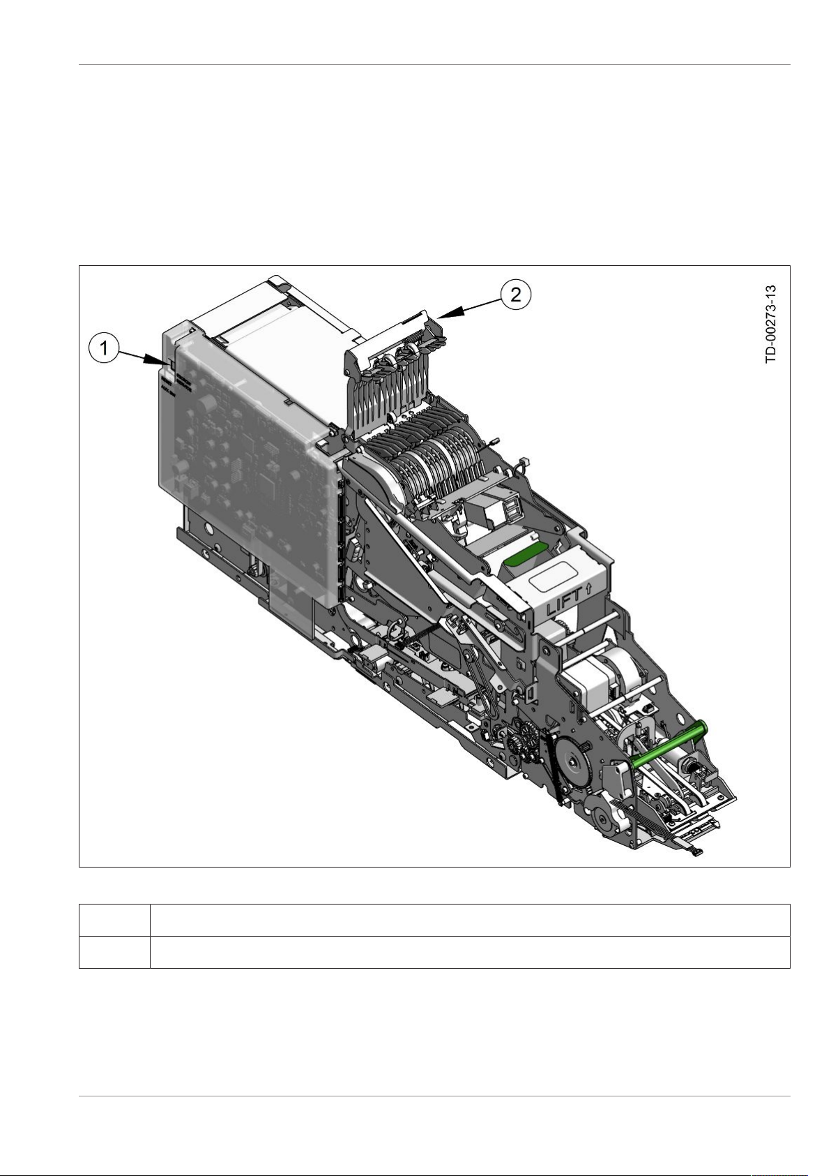
Figure1-2: DN Series™ Check Deposit Module (PBCA Side)
1.2
1.2 Information in this Manual
This manual provides service and maintenance procedures for the check deposit module. Refer to the
operating guide for the system for information about other areas of the system.
1.3
1.3 Safety Precautions
Strictly observe the safety precautions when performing maintenance on the check deposit module. By
following these precautions, you can reduce the risk of equipment damage, severe personal injury, or
death.
Copyright 2019 Diebold Nixdorf
01750333061 A
1-2

Introduction
WARNING
You must observe the following precautions when servicing the check deposit module to
avoid risk of death, severe personal injury, or equipment damage:
lDo not wear loose clothing or jewelry that can become caught in the equipment.
lUse caution to prevent long hair from getting caught in the equipment.
lNever insert scissors, screwdrivers, pens, or other instruments into the equipment un-
less you are instructed to do so in this document. Severe bodily injury, death from
electrical shock, or equipment damage can result.
The check deposit module might have any of the following warning or caution labels. Strictly observe the
following safety concerns to reduce the risk of severe personal injury, or death.
Copyright 2019 Diebold Nixdorf
01750333061 A
1-3
Introduction
1.4
1.4 Signs, Labels and Symbols
The following labels can be used in these instructions, on the system or on the component.
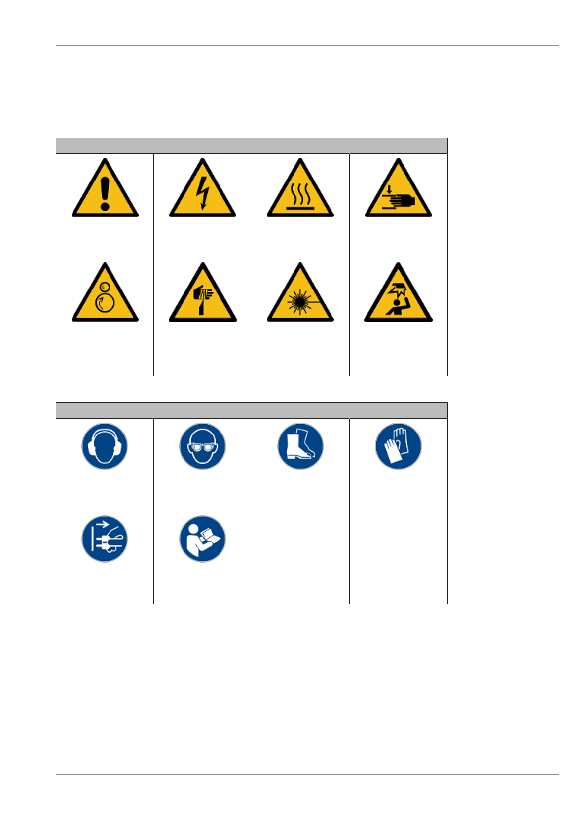
Table1-1: Warning signs used
Warning signs
General
warning sign
Warning of
electric voltage
Warning of
hot surfaces
Warning of
hand injuries
Warning of
feed risk
Warning of
cut injuries
Warning of
laser beam
Warning of
obstacles in the
head area
Table1-2: Used mandatory signs
Mandatory signs
Use
hearing protection
Use
protection eyewear
Use
safety footwear
Use
protective gloves
Pull
mains plug
Read
manual
Copyright 2019 Diebold Nixdorf
01750333061 A
1-4
2
2 General safety instructions for the component
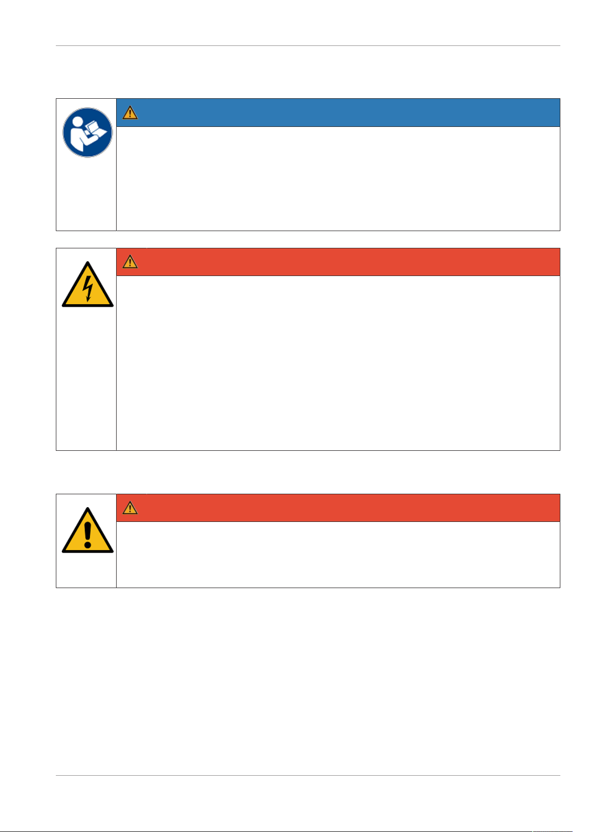
NOTE
Read this entire manual carefully in order to obtain a thorough knowledge with respect to
the system and the components, in addition to their operation and maintenance.
Operate the system and the components correctly in accordance with this manual in order
to avoid injuries and damage to the plant.
Keep this manual available and consult it for guidance when you are unsure about how to
carry out one or another of the procedures.
DANGER
Electrical voltage
Risk of fatal injury through contact with parts carrying electrical voltage! Switch the system
off before performing any cleaning or maintenance tasks.
lSwitch off the power switch for the power distributor.
lSwitch off the UPS, if installed.
lDisconnect the mains connection, if installed, between the UPS (Uninterruptible
Power Supply) and the system itself (see section "General power interruption" in the
operating manual).
lDisconnect the connector of the power supply cable from the electrical socket in-
stalled by the building contractor.
Repairs
DANGER
Repair work on the system or on the components may be carried out only by authorized
specialist staff. Unauthorized opening of the system or repair work carried out improperly
could result in considerable danger to the user. In case of noncompliance, excludes all lia-
bility.
Copyright 2019 Diebold Nixdorf
01750333061 A
2-1

3
3 Maintenance
3.1
3.1 Prerequisite Information
To perform the procedures described in this section, you must know how to perform the following proce-
dures:
• Open the system (refer to the operator manual for the system).
• Place the system in the service mode (refer to the operator manual for the system).
• Remove power from the system (refer to the operator manual for the system).
• Acess and use T/SOP diagnostics.
• Return the system to consumer operation (refer to the documentation for the system control soft-
ware).
Refer also to the specifications defined in Table3-1 through Table3-3.
Table3-1: Dimensions of the Document
Dimension Minimum Maximum
Width 69 mm (2.71 inches) 103 mm (4.05 inches)
Length 150 mm (5.9 inches) 222 mm (8.7 inches)
Thickness 0.07 mm (0.003 inch) 0.18 mm (0.008 inch)
Weight (of check deposit module
with documents)
approximately 15.5 kg (31.9 lb)
Table3-2: Bin Capacity
Bin Document Capacity
Storage 600
Exception 30
Table3-3: Recognized Fonts
MICR line E 13 B and CMC 7
3.2
3.2 Maintenance Procedures
WARNING
The following precautions must be followed when servicing the check deposit module to
avoid risk of equipment damage or severe bodily injury or death from electrical shock:
lRemove loose clothing or jewelry that can become jammed in the equipment.
lNever insert screwdrivers, scissors, pens, or other instruments into the check deposit
module.
Copyright 2019 Diebold Nixdorf
01750333061 A
3-1

Maintenance
This section describes the following maintenance procedures:
• Checking the print quality (Section3.2.1)
• Clearing a jam (Section3.2.2)
• Removing and replacing the inkjet cartridge (Section3.2.3)
• Removing documents from the storage bin (Section3.2.1) and the exception bin (Section3.2.2.2)
3.2.1
3.2.1 Checking the Print Quality
1. Follow the institution's procedures to place the system in the service mode to gain access to the
check deposit module.
2. Access the check deposit module.
3. Unlock the storage bin (Figure3-1).
4. Use the green tab to lower and open the storage bin door.
5. Remove the most recent document from the bin.
6. Inspect the quality of the print. If the print is light or cannot be read, replace the inkjet cartridge
(Section3.2.3).
7. Raise the storage bin door.
8. Lock the storage bin (the lock locks both the storage bin and the exception bin).
9. Return the system to consumer operation.
NOTE
If the storage bin door is not closed, four long beeps will sound until the door of the bin is
closed.
Copyright 2019 Diebold Nixdorf
01750333061 A
3-2

Maintenance
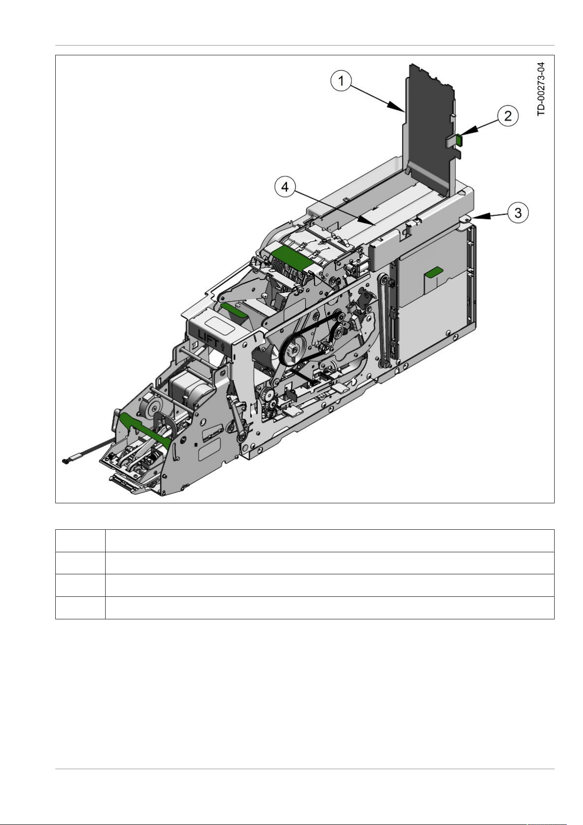
Figure3-1: Storage Bin
1Storage bin lock
2Storage bin door lowered
3Documents in storage bin
4Storage bin release tab
Copyright 2019 Diebold Nixdorf
01750333061 A
3-3

Maintenance
3.2.2
3.2.2 Clearing a Jam
The following areas of the check deposit module should be checked for jammed documents:
• Storage bin (Section3.2.2.1 )
• Exception bin (Section3.2.2.2)
• Input/output assembly (Section3.2.2.3)
• Escrow turn assembly (Section3.2.2.4)
• Escrow assembly (Section3.2.2.5)
• Center and deskew assembly (Section3.2.2.6)
• Escrow roll (Section3.2.2.7)
3.2.2.1
3.2.2.1 Storage Bin
Refer to Section3.2.1 to remove jammed documents from the storage bin.
3.2.2.2
3.2.2.2 Exception Bin
Perform the following steps to remove documents from the exception bin.
1. Unlock the exception bin (same lock locks the storage bin and exception bin).
2. Using the green tab, lift up the cover of the exception bin (Figure3-2).
3. Remove any documents.
4. Close the cover of the exception bin.
5. Lock the exception bin.
NOTE
If the exception bin is not closed, four long beeps will sound until the exception bin is
closed.
Copyright 2019 Diebold Nixdorf
01750333061 A
3-4
Maintenance
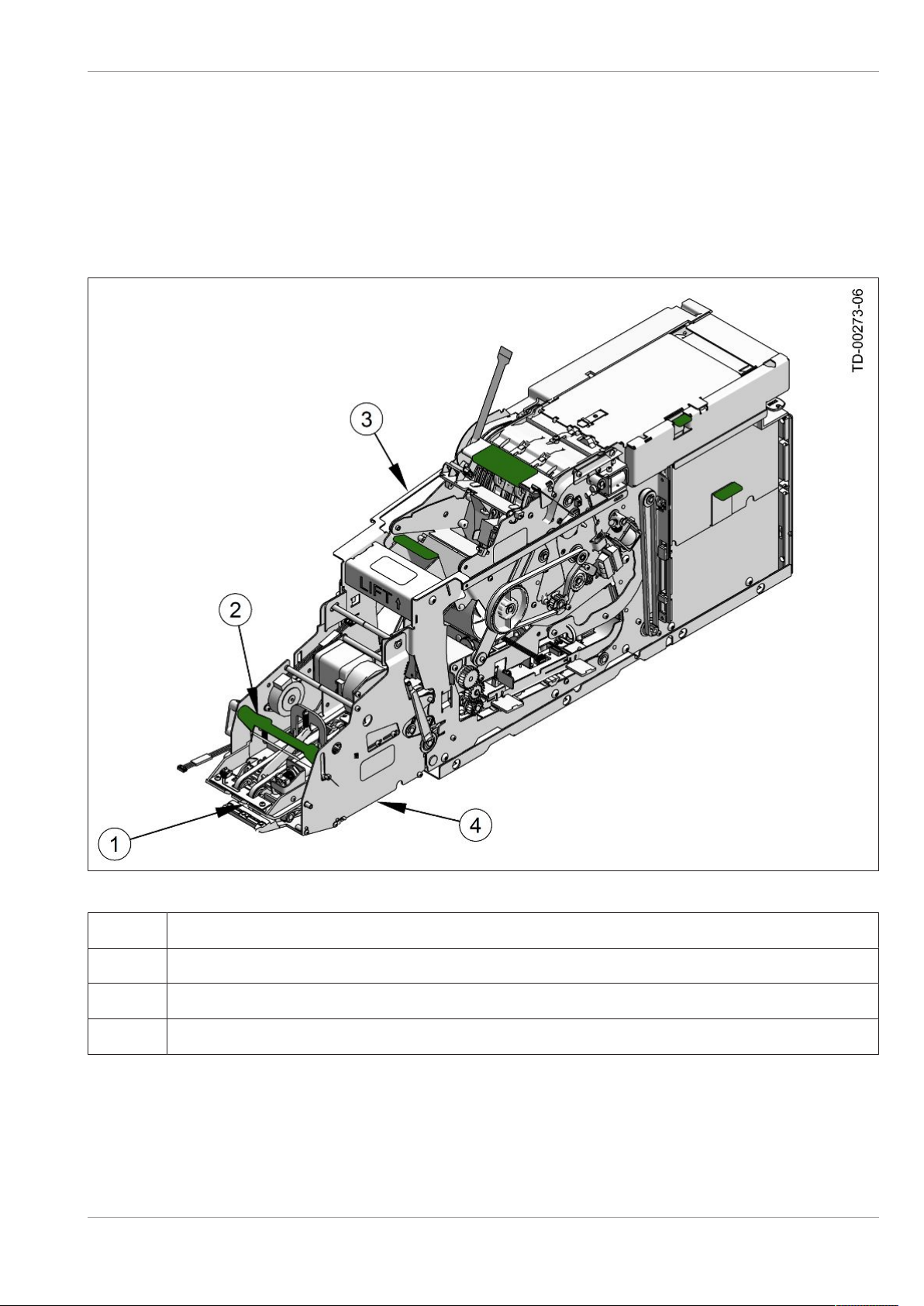
Figure3-2: Green Tab for the Exception Bin
1Exception bin cover
2Green tab
3Exception bin lock (same lock as storage bin)
4Exception bin
Copyright 2019 Diebold Nixdorf
01750333061 A
3-5
Maintenance
3.2.2.3
3.2.2.3 Input/Output Assembly
Perform the following steps to clear jammed documents from the input/output assembly.
1. Refer to your system operating manual to access the check deposit module.
2. Lift the green handle to open the input/output assembly (Figure3-3).
3. Remove any jammed documents.
4. Close the input/output assembly.
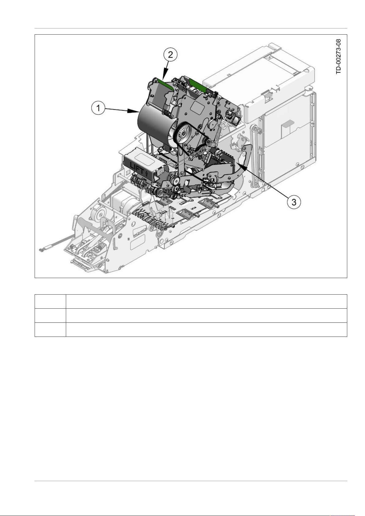
Figure3-3: Input/Output Assembly
1Check here for jams
2Green handle
3Check module
4Input/output assembly
Copyright 2019 Diebold Nixdorf
01750333061 A
3-6

Maintenance
3.2.2.4
3.2.2.4 Escrow Turn
Perform the following steps to remove jammed documents from the escrow turn.
1. Lift the green tab to lift up the escrow turn cover (Figure3-4).
2. Remove jammed documents from the escrow turn.
3. Close and latch the escrow cover.
Figure3-4: Open the Escrow Turn
1Check for jams here
2Open escrow turn cover
3Lift green tab on escrow turn
Copyright 2019 Diebold Nixdorf
01750333061 A
3-7
Maintenance
3.2.2.5
3.2.2.5 Escrow Assembly
1. Pull up on the green tab of the escrow assembly.
2. Lift up the escrow assembly (Figure3-5).
3. Pull up on the kickstand tab. The kickstand props open the escrow at two different positions
(Figure3-6).
WARNING
The escrow assembly is heavy. Make sure the escrow assembly is securely sup-
ported in the open position.
Make sure the escrow assembly is gently lowered into the closed position. Once in the
closed position, make sure it is securely latched. Four audible beeps confirm that the as-
sembly is properly latched.
4. Remove jammed documents located beneath the vertical transport (Figure3-5).
5. Release the tab on the escrow assembly kickstand. Lower and close the escrow assembly
(Figure3-6).
NOTE
There are two conditions when the escrow pivot area might generate four long
beeps:
lIf the escrow pivot area is closed but is not secured, four long beeps will sound until the
escrow pivot area is secured.
lIf the escrow pivot area is open but the module is docked, four long beeps will sound
until the stamp/escrow pivot area is closed and secured.
Copyright 2019 Diebold Nixdorf
01750333061 A
3-8
Maintenance
Figure3-5: Escrow Assembly
1Escrow assembly
2Lift green tab on escrow assembly
3Check for jams here (under vertical transport)
Copyright 2019 Diebold Nixdorf
01750333061 A
3-9

Maintenance
Figure3-6: Positions of the Escrow Assembly Kickstand
1Escrow assembly half open
2Kick stand position 1
3Escrow assembly fully open
4Kick stand position 2
Copyright 2019 Diebold Nixdorf
01750333061 A
3-10

Maintenance
3.2.2.6
3.2.2.6 Center and Deskew Assembly
Perform the following steps to remove jammed documents from the center and deskew assembly.
1. Lift up the escrow assembly, which also raises the center and deskew assembly. Prop open the es-
crow assembly with the kickstand (Figure3-6).
2. Look for jammed documents in the lower center and deskew assembly (Figure3-7).
3. Remove any jammed documents.
4. Release the tab on the escrow assembly kickstand. Lower and close the escrow assembly and the
center and deskew assembly (Figure3-6).
Figure3-7: Center and Deskew (CDS) Assembly Raised
1Hold escrow assembly at touch point
2Prop up the escrow assembly with the kickstand
3CDS upper platen automatically raised
4Look for jams here in the lower center and deskew assembly
Copyright 2019 Diebold Nixdorf
01750333061 A
3-11
Maintenance
3.2.2.7
3.2.2.7 Unload the Escrow Roll
Perform the following steps to remove documents in the escrow roll. The module must have power to
perform this task.
1. Lift up on the green tab to open the escrow turn cover (Figure3-8).
2. Press and hold the unload escrow button on the main PCBA until you hear a beep (Figure3-8).
3. Collect the checks as they are presented. If the escrow turn cover is not open, the checks will be
collected in the exception bin.
Figure3-8: Empty Escrow Roll Button
1Unload escrow button on main PCBA
2Escrow turn cover
Copyright 2019 Diebold Nixdorf
01750333061 A
3-12
Other manuals for DN Series
3
Table of contents
Other DIEBOLD NIXDORF Control Unit manuals

Popular Control Unit manuals by other brands

Solid State Logic
Solid State Logic XLOGIC SUPERANALOGUE X-RACK Stereo EQ user guide

ProFlo
ProFlo PF4001LS installation instructions

Atheros
Atheros Qualcomm QCNFA324 manual

GAPOSA
GAPOSA QCzero instructions

Sintai Optical
Sintai Optical 1DX Quick installation guide

Harman
Harman AMX HPX-AV102-MDP-R quick start guide

WURM
WURM FRIGOLINK ANI-2F1-A manual

RADIKAL TECHNOLOGIES
RADIKAL TECHNOLOGIES Swarm Oscillator RT-311 quick start guide

Hauppauge
Hauppauge mySmarthome user guide

Fuji Electric
Fuji Electric X Series Applications manual

DBA
DBA LaneWalker operating manual

DataComm Electronics
DataComm Electronics 70-0021 Instruction/installation sheet


