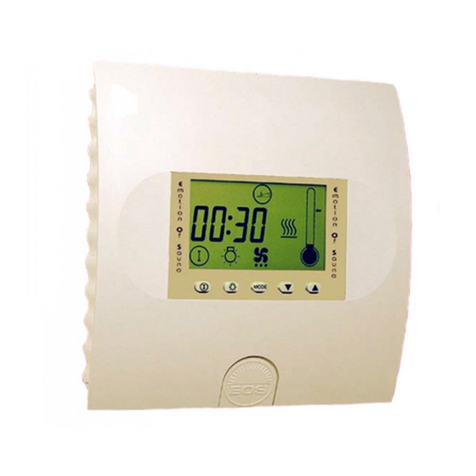
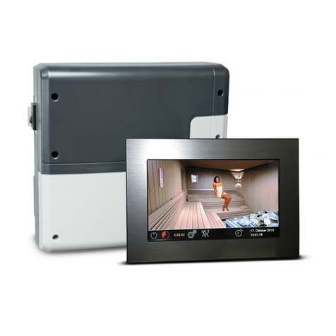
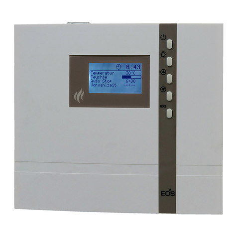
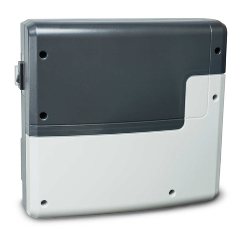
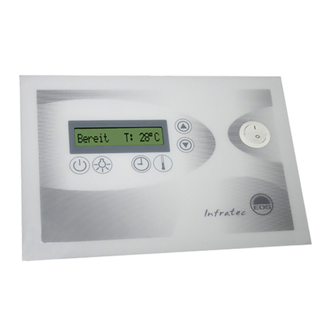
EOS ECON D2 User guide

IPx4
Made in Germany
EOS Econ D2
Installation and operating instruction
sauna control unit
Print no. 29344706en / 30.22
Technical changes reserved
Firmware R4.35
EN

2EN
English
Table of contents
General safety instructions..........................................................................................................................4-8
Safety levels ...................................................................................................................................................4
Mounting and electrical installation ................................................................................................5-6
Operator instruction...............................................................................................................................6-8
Standards and regulations.......................................................................................................................8
Identification.........................................................................................................................................................9
Scope of delivery.............................................................................................................................................. 10
Accessories .........................................................................................................................................................10
Technical data.................................................................................................................................................... 11
Intended use...................................................................................................................................................... 12
Installation of the control unit...............................................................................................................13-16
Installation site............................................................................................................................................13
Installing the control unit........................................................................................................................ 14
Wall mounting............................................................................................................................................. 16
Connecting the sensor cables ..................................................................................................................... 17
Installation of the main sensor ............................................................................................................ 17
Electrical installation.................................................................................................................................19-23
Installation sequence, Connections................................................................................................... 19
Connection diagram for sauna heaters up to 9 kW...................................................................... 20
Connection diagram for sauna heaters above 9 kW....................................................................20
Main board assignment and components......................................................................................21
Installation diagram................................................................................................................................. 21
Connecting the sensor cables.............................................................................................................. 22
Connecting the consumer lines .......................................................................................................... 23
Operation......................................................................................................................................................24-29
General information............................................................................................................................ 16
The user interface .......................................................................................................................... 16
Operating buttons.........................................................................................................................16
Default display Stand-by............................................................................................................. 17
Default display in operation....................................................................................................... 17
Energy-saving display................................................................................................................... 17
Symbol description .......................................................................................................................18
Operation principle.......................................................................................................................19
Initial commissioning ................................................................................................................... 20
Switching your sauna on / off in dry mode ..........................................................................21
Temperature query........................................................................................................................ 21

3
EN
Individual settings......................................................................................................................................30-34
Cabin temperature...................................................................................................................................30
Auto-stop / heat-up time limitation................................................................................................... 31
Cabin lighting.............................................................................................................................................32
Preselection time......................................................................................................................................33
Activate / deactivate the preselection time....................................................................................34
Advanced settings .....................................................................................................................................35-38
Change language .....................................................................................................................................35
Change time...............................................................................................................................................35
Switching between °C and °F............................................................................................................... 36
Switching user profiles (P1-P4)............................................................................................................ 36
Activate / deactivate the child lock....................................................................................................37
Activate / deactivate the Safety...........................................................................................................37
Activate / deactivate the Life - Guard................................................................................................ 38
Life-Guard ...........................................................................................................................................................39
In Stand-by..................................................................................................................................................39
Switching on the sauna unit with Life-Guard................................................................................. 40
Holiday home - Holiday park mode........................................................................................................... 41
Heating time limitation..................................................................................................................................42
Device fuses........................................................................................................................................................ 43
Error messages.................................................................................................................................................. 44
The device„Switch-off“ switch .................................................................................................................... 46
Recycling ............................................................................................................................................................. 47
Service address ................................................................................................................................................. 47
General Terms and Conditions of Service................................................................................................ 48

4D
Safety instructions and important operating instructions are classied. Please familiarise yourself
with the following terms and symbols:
WARNING
Warning
Indicates a hazardous situation which, if not avoided, could result in death or serious injury.
CAUTION
Caution
Indicates a hazardous situation which, if not avoided, could result in minor or moderate in-
jury.
NOTICE
Notice
Indicates a hazardous situation which, if not avoided, will result in damage to the unit.
General safety instructions
Safety levels

5
D
Mounting and electrical installation
These installation instructions are intended for qualied personnel familiar with
the laws and regulations applicable to electrical installations at the installation
site. Observe the following general safety instructions during mounting, cong-
uration and commissioning of the product.
Risk to life and limb and risk of re
Risk to life and limb from electric shock and re in the event of improper or faulty electrical
connection. This risk also applies following completion of the installation work.
• The electrical installation of the relay box and other electrical systems or equipment with
a xed mains connection must only be performed by a trained electrician from an author-
ised electrical company.
• Observe the stipulations inVDE 0100 part 703 or the applicable local legal requirements.
• The system must be completely disconnected from the mains supply before commencing
installation and repair work.
• The housing cover must only be removed by a specialist.
Fire hazard from overheating
Insucient ventilation can lead to device overheating and re. Flammable parts inside sau-
na must not exceed a temperature of 140°C when the unit is operated as intended or in the
event of a malfunction.
• Do not install control panels, relay boxes and modules in enclosed cabinets or wood pan-
elling.
• Observe the sauna heater manufacturer’s safety and installation instructions.
• Observe the cabin manufacturer’s safety and installation instructions.
• Touchable glass surfaces on the outside of the cabins must not reach more than 76°C. Oth-
erwise provide proper protection.

6D
Damage to the unit
Corrosive or heavy saline atmospheres damage the contacts in the control panel, in the relay
box and in the sensors.
• The control panel and sensors should not be installed in a corrosive or heavy saline atmos-
phere.
Damage due to incorrect mounting location
The control unit is not suitable for outdoor use!
• It may be operated only inside buildings and may not be exposed to environmental condi-
tions such as extreme humidity and moisture or the possible formation of condensation or
corrosive substances in the ambient air, as well as other weather conditions.
• Similarly, excessive cold and extreme exposure to sunlight must be prevented.
• Protect the unit accordingly if there is an increased risk of mechanical damage.
Operator instruction
The operator of the infrared or sauna cabin must be instructed on the general safety instruc-
tions during commissioning.The operator must be given a copy of the operating instructions.
The operator must make the end user aware of safety instructions that are relevant to the
end user.
Risk of electric shock
A risk to life and limb from electric shock and re arises in the event of improper repair work.
This risk also applies after work is completed.
• The housing covers may only be removed by a specialist.
• Repairs and installations may only be performed by a trained specialist.
• The system must be completely disconnected from the mains supply before commencing
repair work.
• Use only original spare parts from the manufacturer.

7
D
Fire hazard
Objects placed on the sauna heaters can ignite and cause re.
• Do not place objects on the sauna heater.
• If you switch on the sauna heater using a pre-set timer or a remote control, use a cover
protection sysem for the heater or install a suitable safety device.
• Inspect the cabin prior to switching it on.
• When using control units with a remote control option (see EN 60335-1), protection from
switching on a covered sauna heater is required.
Risk of burns and chemical burns
Touching hot parts may lead to skin burns.
• The operator must be familiar with the unit’s hot parts and be able to identify them.
• The operator must be familiar with the settings for the heating time and understand how
to adjust it.
Health risks
Spending time in an infrared or sauna cabin can lead to serious health risks or even death for
persons with health impairments.
• Persons with health impairments who spend time in a sauna must consult a doctor before
entering an infrared or sauna cabin.
Equipment damage due to overuse
The uninterrupted operation time of the sauna cabin(s) can lead to property damage.
• If the sauna cabin is used commercially, the heating time must be set so that it switches o
automatically after a specic period of time.
• If the heating does not switch o automatically after a dened heating period, cabin use
must be supervised at all times.
• Inspect the cabin before each use.

8D
Operation by children or persons with reduced mental capacity
Children and persons with reduced mental capacity can put themselves at risk.
• Children must be supervised to ensure they do not play with the unit.
• Children under 8 years of age may not operate the sauna cabin.
• The settings for the heating time may only be carried out by children under 8 years of age
if they are supervised by an adult.
• The sauna cabin must only be used by persons with reduced mental capacity, or limited
physical or sensory abilities under supervision or if they have been previously instructed in
its use and understand the risks.
• Children and persons who have not received proper instruction may not clean or service
the system.
Standards and regulations
For an overview of the standards that were observed during design and construction of
the sauna heaters, please refer to the individual product‘s technical data sheet that can be
downloaded from www.eos-sauna.com.
Local regulations also apply to the installation and operation of heating, sauna, and steam
room systems.

9
EN
Identication
The Econ D2 control unit consists of a main unit, a temperature sensor with connecting cables and
small accessories, and is used to operate a sauna cabin.
Additional devices can be connected to the control unit for control of a sauna cabin, for example,
lighting and power extension devices.
Saunasteuergerät
IPX4
Type EOS Econ D2
Art. Nr. 94 6138 00
400V 3N ~ 50 Hz
Maximale Schaltleistung 9 kW
Made in Germany
EOS SAUNATECHNIK GmbH, Schneiderstriesch 1, 35759 Driedorf
S-No. 0000506.21
A
B
C
D
E
F
G H
A. Name
B. Model
C. Item number
D. Operating voltage
E. Country of origin
F. Manufacturer
G. Production date
H. Serial number
Foreseeable misuse
Identification of the units
The nameplate is attached to the underside of the base of the relay box housing.
The following are considered instances of foreseeable misuse:
The control and sensor cable plugs are plugged in incorrectly.
The unit is operated without knowledge of or compliance with the safety instructions.
Operating, service and maintenance requirements are not observed.
The unit is operated after technical or other modications are made to the relay box.
The unit is operated by children under the age of 8 years or by children above the age of 8
years and persons with reduced mental capacity without being thoroughly instructed in its
use or supervised.
The manufacturer is not liable for unauthorised modications made to the equipment and dam-
ages resulting from these modications. The person modifying the equipment alone shall bear the
associated risk.
Read the General Safety Instructions.

10 EN
4
5
1
2
3
6
a
b
c
d
1
Scope of delivery
1. Control unit Econ D2
2. Temperature sensor kit, comprising
Sensor housing (a)
Board with temperature sensor KTY and safety temperature limiter (b)
2 mounting screws 4 x 40 mm (c)
Sensor line 2 m, red (d)
Line for safety temperature limiter 2 m, white
3. Plstic bag with 3 mounting screws 4 x 25 mm.
4. 5 rubber cable glands
5. Spare safety temperature limiter
6. 1 installation and operation manual
Delivery contains the following items:

11
EN
Voltage (power supply) 400 V 3N ~ 50 Hz
Switch output max. 9 kW resistive load (AC1 mode). Can be expanded
to 36 kW via the connection of power switching devices
Fuse 3 x 16 A
Heating time limit: 6 h, 12 h
Display LCD display 65 x 37 mm, graphic
Dimensions (HxWxD) 220 x 250 x 67 mm
Protection type IPx4 acc. to EN 60529 splashwater protection
Temperature control range 30 to 115 °C
Sensor system (temperature) KTY-sensor with safety temperature limiter 139 °C
Control characteristic Two-point control with xed hysteresis of 3K. For control via
the stove sensor oset of 7K to compensate the higher tem-
peratures directly below the cabin ceiling
Light max. 100 W
Ambient temperatures -10 °C to +40 °C
Storage temperature -20 °C to +70 °C
T
emperature display stove sensor
Current value on the stove sensor minus 7K to compensate
the higher temperatures directly below the cabin ceiling
Technical data

12 EN
Intended use
Important note!
The control unit is not suitable for outdoor use!
It must only be used inside buildings and may not be exposed to environmental condi-
tions such as extreme humidity or moisture with possible condensate formation or corro-
sive substances in the ambient air and other weathering. Excessive exposure to cold and
intense solar radiation should be avoided as well. If there is an increased risk of mechani-
cal damage, the control unit must be protected accordingly.
In conjunction with a suitable sauna heater, the Econ D2 control unit is intended to be used only
to heat sauna cabins. It is suitable for residential and commercial sauna cabins. Any further use is
deemed not to be in accordance with the intended purpose!
The intended use also includes compliance with the usual operating, maintenance and servicing
conditions.
The control unit is intended only for mounting on the wall.

Installation
All lines should be routed before installing the control unit. The connections can be plugged in
after installation, since the control unit’s front panel can be removed.
Data lines must be routed and connected in such a way that they are not openly accessible. They
should be routed between the insulation and the outer wall of the cabin. Cabin insulation must be
installed in such a way that the temperature in the area in which cables are routed cannot exceed
65°C.
If the data lines are installed outside on the wall, they should be protected by a cable duct.
A B C
A. Partially recessed installa-
tion
B. Partially recessed installa-
ton, alternative cable rou-
ting
C. Surface installation
The control unit may be mounted only outside of the sauna cabin. Recommended places are:
Outer wall of the cabin, but insider of the building
Plant room or a comparable place, in order to suit the local installation situation.
If empty conduits for electrical installations are already present, this dictates the position of the
relay box.
Installation site
NOTICE
Electronics malfunctions
Routing data and power supply lines together can lead to electronics malfunctions because, e.g.
because the sensor will not be detected.
Do not route sensor and sauna bus lines together with power supply lines.
Route separate cable conduits.
13
EN

The following work must be completed before
you mount the control unit:
Determine the mounting site, see„Instal-
lation Site“.
Route the lines to control unit.
Installing the control unit
eye height
Mounting on the cabin wall
WARNING
Risk to life and limb and risk of re
Risk to life and limb from electric shock and re in the event of improper or faulty electrical con-
nection. This risk also applies following completion of the installation work.
Do not install relay boxes in enclosed cabinets or wood panelling.
Site requirements
Ambient temperature during operation -10°C to 35°C
Relative air humidity during operation 30% to 75%
Ambient air may not be corrosive or have high salt content
Storage temperature -20°C to +60°C
Stable wall able to carry unit‘s weight (by recessed installation min. available 35 mm depth)
Power supply 400 V 3N ~ 50 Hz nearby
All cable lines and connections must be accessible for servicing.
Fig. 1
ca. 35 cm
14 EN

NOTICE
Damage due to steam and humidity
Condensation can form when the door is opened, which can fog over the display. This can lead to
the formation of condensation in the control unit and malfunctions.
Mount the control unit outside of the area in which the humid warm air mixture can spread.
Mount the control unit on the hinge side of the door.
Tools required:
Saw for cutting the wall (only for recessed installation in the wall).
Screw driver.
Taut wire, as needed.
Wooden screws (included in the scope of delivery): 3 pcs when mounting on the wall
Removing the front cover
Remove the front cover from the
housing.
1. Unscrew the screw on the top of
the housing.
2. Swivel the front cover and remove
it downward.
Preparing the air inlets
Determine the line openings in the hous-
ing.
A. Openings for mains, heater, light lines
B. Openining for sensor and limiter fuse
Break the plates from out of the openings.
Insert the bushings.
AB
Fig. 2
Fig. 3
15
EN

1. Drill one (1) hole above and two (2)
holes with Ø3 mm in the wall as shown.
2. Screw in the upper screw.
3. Allow the screw to protrude approx. 3
mm so you can later hook in the hous-
ing.
4. Pull the lines through the openings into
the unit housing.
5. Mount the housing on the wall::
a) Hook the housing into the upper
screw using the upper mounting-
hole (A).
b) Securely tighten the housing in the
two lower holes (B).
6. Connect the lines (see “Electric Installa-
tion).
Mounting the unit on the wall
Semi-recessed mounting
3 mm
eye height
1. Prepare a wall cut-out:
Height x Width: 210 x 200 mm, Installation
depth: min. 35 mm.
2. Pull the lines through the openings into
the unit housing.
3. Fit the housing into the cut-out and fasten
it with 4 screws (C) to the wall.
4. Connect the lines (see “Electric Installa-
tion).
A
B
C
C
C
C
Fig. 5
Fig. 4
Fig. 6
210 mm
210 mm
ca. 35 cm
17 cm
17,7 cm
16 EN

17
EN
1. Mount the oven sensor in cabins up to 2 x 2m
according to g. 7 and 9, in larger cabins ac-
cording to g. 8 and 9.
20 cm
2. Drill a hole to lead the cable through, prefer-
ably through the middle of one of the wood-
en boards.
3. Lead the sensor cable through the drilled
hole and attach it to the sensor line accord-
ing to Illust. 10.
4. The cables for the limiter (white) and the
temperature sensor (red) are connected to
the sensor circuit board acc. Fig. 10. Engage
the sensor board into the casing.
Installation of the main
sensor
35 cm
> 2 x 2 m
Fühlerleitung
19 cm
< 2 x 2 m
Fühlerleitung
Connecting the sensor cables
You should not install sensor and power supply
lines together, or lead them through the same
feedthrough. This can lead to interferences in
the electronics, such as "uttering" in the re-
lays. If it is necessary to lay the cables down
together, or if the line is longer than 3m, use a
shielded sensor cable (4 x 0.5 mm²).
Connect the shielding to ground in the control
unit.
Please observe that the following dimensions
relate to the values stipulated during the unit
inspection acc. EN 60335-2-53. The heater
sensor must always be installed at the point
where the highest temperatures are to be
expected. Illust. 7-9 give you an overview of
the mounting point of the sensor.
Housing
Fig. 7 Fig. 8
Fig. 9
Fig. 10
Red
(Sensor)
Sensor circuit board
White
(STB)
Sensor
Limiter weiß / white
rot / red
Bankfühler (optional)
Auxiliary sensor (optional)
Feuchtefühler (optional)
Humidity sensor (optional)
X2
Ub
G
E
KTY
STB
STB
KTY
5. Lead the sensor cables through the
right cable intake into the control unit.
Install the sensor cables inside the con-
trol unit as shown in Fig. 11.
Connect the sensor cables as shown in Fig.
12. In order to do this, pull the plug X2 from
the circuit board and plug it back in after the
connection.

18 EN
Bore hole
Sauna ceiling
Centre sensor housing
on middle section of
the wooden plank.
Sensor cables
connect to ground (PE) by
shielded sensor cable
12 : 00
Thermal
fuse
Fig. 11
6. After completed installation and before commissioning of the con-
trol unit the line for overheating protection fuse must be checked
for proper functionality. For this disconnect one of the white cable
wires at X2 connector. The respective error message appears in the
display. Re-connect the wire.
Sensor
Limiter weiß / white
rot / red
Bankfühler (optional)
Auxiliary sensor (optional)
Feuchtefühler (optional)
Humidity sensor (optional)
X2
Ub
G
E
KTY
STB
STB
KTY
Temperature sensor
with STB
X2
F2
Equipment damage due to incorrect connection.
Mixing up the connection on X2 connection can cause the fuse F2
to blow and damage the control (for replacement please refer to the
chapter„Device fuses“)
Notice
Fig. 12

19
EN
Connections
Recommended installation sequence
As a rule, only a xed connection may be connected to the mains supply, whereby a conguration
is provided that makes it possible to separate the system from the mains supply with a contact
opening width of at least 3 mm (all poles).
All electrical installations and all connecting lines that are installed inside a cabin must be suitable
for installation in a sauna or IR cabin (IPx4).
The relay box is connected with a live current of 400 V 3 N ~ 50 Hz and fused separately with 3 x 16
A. A 16 A cut-out with at least K characteristic must be used for fuse protection.
Before commencing installation, ensure that the control unit and the temperature sensor are
mounted. Furthermore, all cabin work must be complete: sauna heater, light, etc.
Complete installation in the following sequence:
• Plug the S-Bus and sensor lines into the relay box.
• Connect the consumer lines (sauna heater, light, fan, etc.) to the relay box.
• Establish connection to the power supply.
• In a multi-cabin installation: Program the cabin address.
• Switch on the relay box and control panel.
• Congure additional settings at the control panel, e.g. target temperature.
This chapter describes how to connect the relay box‘s circuit board lines.
For information on setup of the control panel, see chapter Commissioning
Electrical installation
WARNING
Risk of electric shock
A faulty electrical connection poses the risk of an electric shock. This risk also applies fol-
lowing completion of the installation work.
• Disconnect the system entirely from the mains supply.
• If retrotting is required, the housing must only be opened by trained personnel.
• Electrical installation must only be carried out by a qualied and licensed electrician.
• The unit must be connected to the power supply according to the circuit diagram and the ter-
minal scheme

20 EN
X1
ECON
P max. 9 kW
UVWNL1 L2 L3
Light
N
Li
N
V1
N
S1
Sensor
Limiter weiß / white
rot / red
X2
max. 100 W
139°C
KTY 10/5
400 V 3N ~ 50 Hz
3x16A
400 V 3N ~ 50 Hz
max. 100 W
X1
P max. 9 kWP max. 18 kW
LSG
400 V 3N ~ 50 Hz
Light
L
N
ECON
UVWNL1 L2 L3 N
V1
N
S1
Sensor
Limiter weiß / white
rot / red
X2
139°C
KTY 10/5
3x16A
Connection diagram for sauna heaters up to 9 kW
Connection diagram for sauna heaters above 9 kW
Other manuals for ECON D2
1
Table of contents
Other EOS Control Unit manuals
Popular Control Unit manuals by other brands

Trinamic
Trinamic PD-1160 Getting started

Dyna-Flo
Dyna-Flo 570 Operation, Parts, and Instruction Manual

GEM
GEM 613 Installation, operating and maintenance instructions

Elektrogas
Elektrogas VML Series Technical manual

Leadshine
Leadshine 2CS3E Series user manual

Hacker
Hacker UAV Control Opto Pro Series manual