Diener femto User manual

- 1 -
OPERATING
INSTRUCTIONS
Type: Femto
Please read this manual carefully before installing the
machine.
L
O
W
P
R
E
S
S
U
R
E
P
L
A
S
M
A
S
Y
S
T
E
M

- 2 -
S
Su
um
mm
ma
ar
ry
y
O
Of
f
D
De
el
li
iv
ve
er
re
ed
d
C
Co
om
mp
po
on
ne
en
nt
ts
s
1. Cabinet/
Basic Unit
2. Gas supply
3. Connections
4. Vacuum-
chamber
5. Carrier
6. Electrodes
7. Control
8. Generator
9. Vacuum
Pump
10. Options
Customer:
Date of delivery:
Please note, that for the handling with your machine, it is only neccesary to read the marked chapters!
1.1.1 1.1.2 1.1.3 1.1.4 1.1.5 1.1.6 1.1.7 1.1.8
1.4.1 1.4.2 1.4.3 1.4.4 1.4.5 1.4.6
1.5.1 1.5.2 1.5.3 1.5.4 1.5.5 1.5.6 1.5.7 1.5.8 1.5.9
1.6.1 1.6.2 1.6.3 1.6.4 1.6.5 1.6.6
1.7.1 1.7.2 1.7.3
1.8.1 1.8.2 1.8.3 1.8.4 1.8.5 1.8.6
1.9.1 1.9.3 1.9.4 1.9.5 1.9.6 1.9.7 1.9.8
1.10.1 1.10.2 1.10.3 1.10.4 1.10.5 1.10.6 1.10.7 1.10.8
1.10.10 1.10.11 1.10.12 1.10.13 1.10.14 1.10.15 1.10.16 1.10.17
1.10.19 1.10.20 1.10.21 1.10.22 1.10.23 1.10.24 1.10.25 1.10.26
1.10.27 1.10.28 1.10.29 1.10.30
1.2.1 1.2.2 1.2.3 1.2.4 1.2.5 1.2.6 1.2.7
obligatorisch
1.10.18
1.10.9
1.9.2

- 3 -
S
Su
um
mm
ma
ar
ry
y
O
Of
f
D
De
el
li
iv
ve
er
re
ed
d
C
Co
om
mp
po
on
ne
en
nt
ts
s
11
.
Special
Options:
12
.
Remarks:
13
.
Specify
Connections:

- 4 -
T
Ta
ab
bl
le
e
O
Of
f
C
Co
on
nt
te
en
nt
ts
s
1. Delivered components and description.................................................
2. Connecting of the machine …………………………………………………..
3. Technical features of machine ..............................................................
4. Safety warnings ....................................................................................
5. Maintenance .........................................................................................
6. Emergency maintenance ......................................................................
7. Spare part list........................................................................................
8. EG declaration of conformity.................................................................
9. Warranty................................................................................................
10. Information according plasma processes.............................................
11. Index.....................................................................................................
12. Circuit diagram .....................................................................................
Manual for
Low Pressure Plasma Systems
Of following production series: Femto
Producer: Diener electronic GmbH + Co. KG
Talstr. 5
D-72202 Nagold
Germany
Tel.: 00 49 (0) 74 52 / 8 88 07 – 0
Fax: 00 49 (0) 74 52 / 8 88 07 – 50
Internet: www.plasma.de
As of: 2008-12-31
Copyright: Diener electronic GmbH + Co. KG
All rights reserved. This publication may be reproduced or transmitted only
with permission in writing form from the publisher (Diener electronic GmbH +
Co. KG)
Technical modifications are subject to change.
© Diener electronic GmbH + Co. KG

- 5 -
Checkliste
1. Schaltplan geprüft
2. Baratron Datenblatt dabei
3. MFC Datenblatt dabei
4. Generatordoku dabei
5. Pumpendoku dabei
6.
7.
8.
9.
10.
Dies wird dem Kunden nicht ausgeliefert.
Datenblätter in jedes Kapitel gleich dazuheften.

- 6 -
1.1 Delivered Components and Description
1.1 Cabinet / Basic Unit
1.1.1 BASIC UNIT TYPE A
•Dimensions: Width approx. 345 mm
Depth approx. 420 mm (570 mm incl. plugs)
Height approx. 211 mm
1.1.2 BASIC UNIT TYPE B
•Dimensions: Width approx. 560 mm
Depth approx. 600 mm (750 mm incl. plugs)
Height approx. 310 mm
1.1.3 BASIC UNIT TYPE C
•Dimensions: Width approx. 562 mm
Depth approx. 420 mm (570 mm incl. plugs)
Height approx. 211 mm
1.1.4 BASIC UNIT TYPE D
•Dimensions: Width approx. 211 mm
Depth approx. 420 mm (570 mm incl. plugs)
Height approx. 570 mm
1.1.5 BASIC UNIT TYPE E
•Dimensions: Width approx. 500 mm
Depth approx. 550 mm (700 mm incl. plugs)
Height approx. 460 mm

- 7 -
1.1.6 BASIC UNIT TYPE F
•Dimensions: Width approx. 500 mm
Depth approx. 550 mm (700 mm incl. plugs)
Height approx. 600 mm
1.1.7 BASIC UNIT TYPE G
•Dimensions: Width approx. 350 mm
Depth approx. 600 mm (750 mm incl. plugs)
Height approx. 860 mm
1.1.8 BASIC UNIT TYPE H
•Dimensions: Width approx. 600 mm (850 mm incl. plugs)
Depth approx. 800 mm
Height approx.1700 mm
- 8 -
1
1.
.2
2G
Ga
as
s
S
Su
up
pp
pl
ly
y
SELECTION
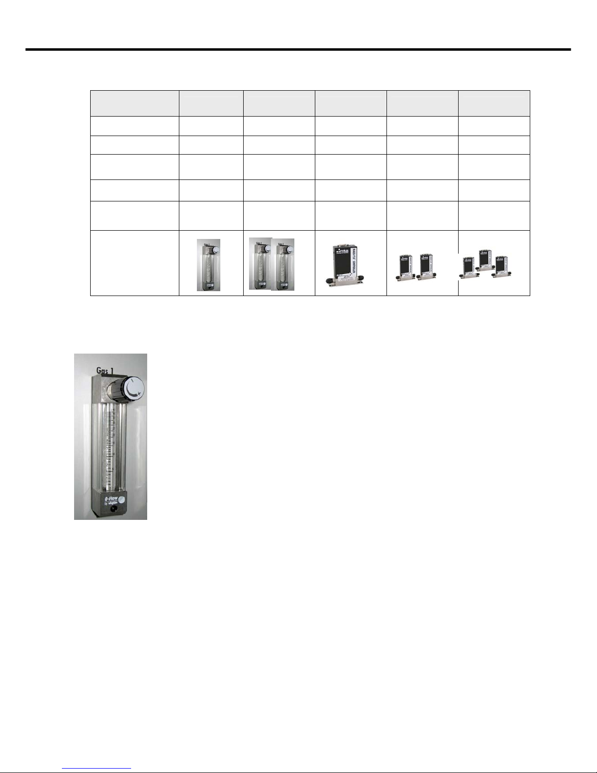
GAS SUPPLY 2.1 TYPE A2.2 TYPE B2.3 TYPE C2.4 TYPE D2.5 TYPE E
Qty. of gas
channels 1 2 1 2 3
Material stainless steel stainless steel stainless steel stainless steel stainless steel
Description needle valve needle valve MFC MFC MFC
Manufacturer Vögtlin Vögtlin MKS MKS MKS
Available
flow values in
sccm on request on request on request on request on request
Figure
The handling of the needle valve is very easy. To control the gas flow and
therefore the process pressure, the valve will be opened or closed.
The direction (to open and close the valve) is easily to see.
Please note following things:
•If the valve is completely closed, the plasma will turn off after
consumption of tail gas in the tubes.
•The gas flow ball, in the glass gauge tube of the valve,
sometimes gets caught at the upper end of the scale. That
happens when the valve has been opened too much. To detach
the ball, knock at the security glass of the gauge tube.
•Liquids may damage the needle valve. (Agglutinating of the
valve)
•Some aggressive solutions and gases (like HNO3, HCl, NH4,
…) may destroy the sealing of the needle valve. If you want to use
such chemicals, you should order the Special Option with a Kalrez
– Sealing. To ensure a long-lasting and save operating with such
materials, the complete machine and pump has to be modified
(Corrosive – Gas – Version).
•At usage of aggressive gases and chemicals, please contact
us to clarify if your machine is suitable for this process.

- 9 -
1
1.
.2
2G
Ga
as
s
S
Su
up
pp
pl
ly
y
There are two variations of MFC’s (Mass Flow
Controller)
Variation 1: manual control,
which has to be controlled like
the needle valve
And Variation 2: PC – controlled MFC. Detailed
Information according the handling of PC – controlled
MFC’s you will find in chapter 1.7 Controls, section PC-
Control.
Control MFC

- 10 -
1
1.
.3
3C
Co
on
nn
ne
ec
ct
ti
io
on
ns
s
1.3.1 Connections for basic unit type A
•Gas: 6mm Swagelok
•Voltage / Power: 230 V / 16 A
•Exhaust Air: tube, inner diameter approx. 10 mm
1.3.2 Connection for basic unit type D
•Gas: 6mm Swagelok
•Voltage / Power: 230 V / 16 A
•Exhaust Air: tube, inner diameter approx. 10 mm
Type label
Timer
Evacuation tube for
vacuum chamber
Ventilator
Connection
pump
Main power
supply
(220 – 240 V /
50/60 Hz)
Ventilation
Fuse
Gas connection
6 mm Swagelok
Ventilator
Connection
pump
Main power
supply
(220 – 240 V /
50 Hz)
Evacuation tube for
vacuum chamber
Type label
Ventilation
1 Gas connection
6 mm Swagelock
2 Gas connection
6 mm Swagelock
Fuse
- 11 -
1
1.
.3
3C
Co
on
nn
ne
ec
ct
ti
io
on
ns
s
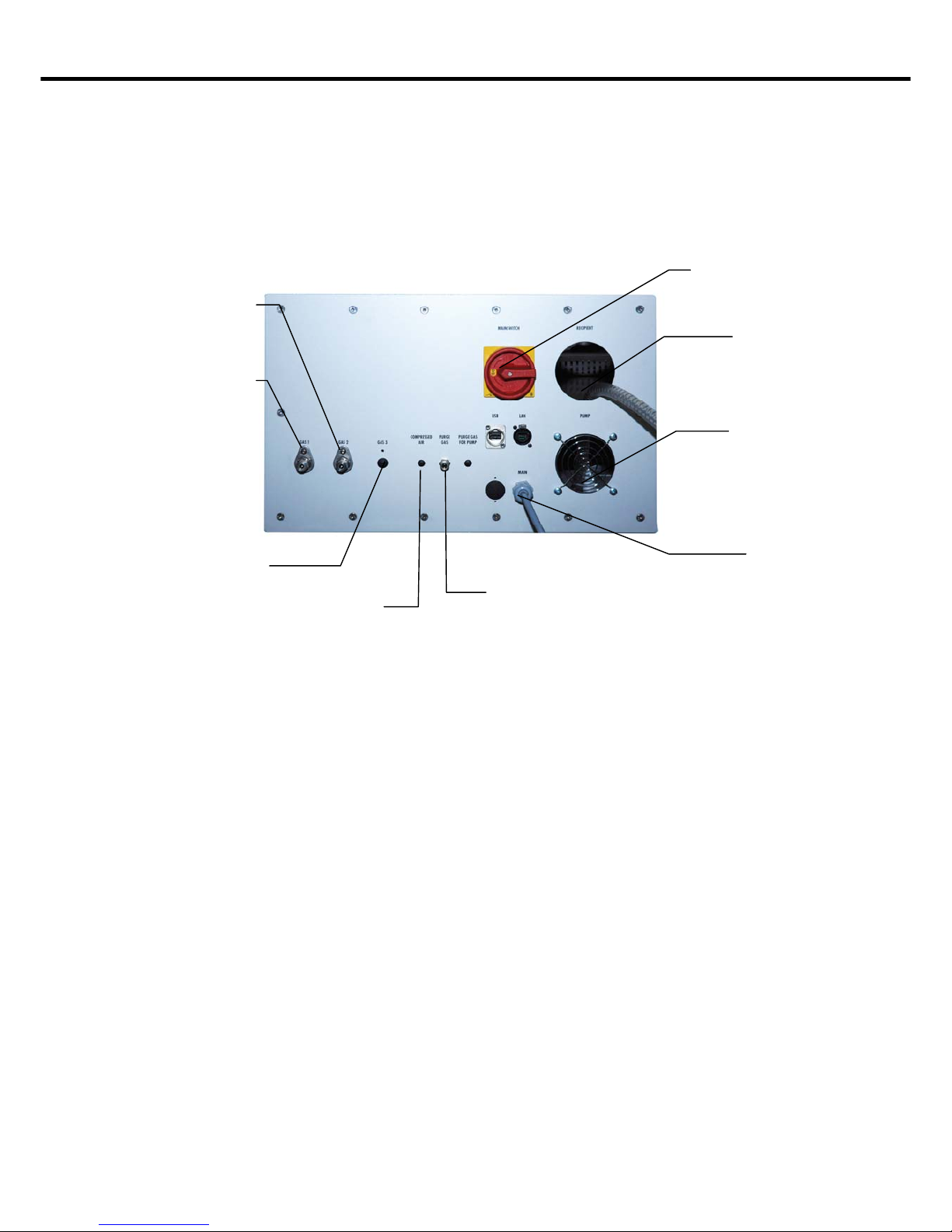
1.3.3 Connections for basic unit type H
•Gas: 6mm Swagelok
•Voltage / Power: 400 V / 16 A
•Exhaust Air: tube, inner diameter approx. 10 mm
Gas connection 1
Gas connection 2
Evacuation tube
f
or vacuum
c
hamber
Ventilation
Main power
switch
Power supply
Scavenging gas /
flushing gas
connection
Compressed
air
Gas connection 3
(optional)

- 12 -
1
1.
.4
4V
Va
ac
cu
uu
um
m
C
Ch
ha
am
mb
be
er
r
SELECTION
VACUUM
CHAMBER 1.4.1
TYPE A1.4.2
TYPE B1.4.3
TYPE C1.4.4
TYPE D1.4.5
TYPE E1.4.6
TYPE F
Chamber
configuration round round round round round rectangular
Material:
vacuum chamber stainless
steel
borosilicate
glass
borosilicate
glass quartz glass quartz glass stainless steel
Chamber cover cap cap hinged door cap hinged door hinged door
Covering material aluminium,
glass pane
aluminium,
glass pane
aluminium,
glass pane
aluminium,
glass pane
aluminium,
glass pane
aluminium,
glass pane
Inner diameter Dia. 100 mm
D 278 mm
Dia. 95 mm
D 320 mm
Dia. 95 mm
D 320 mm
Dia. 95 mm
D 320 mm
Dia. 95 mm
D 320 mm
W 103 mm
D 285 mm
H 103 mm
Opening diameter of
recipient Dia. 100 mm Dia. 90 mm Dia. 90 mm Dia. 90 mm Dia. 90 mm W 103 mm
H 103 mm
Chamber volume approx.
2 litres
approx.
2 litres
approx.
2 litres
approx.
2 litres
approx.
2 litres
approx.
3 litres
Application areas
standard
plasma
processes,
small batch-
and
laboratory
equipment
for pure
plasma
processes,
small batch-
and laboratory
equipment
for pure
plasma
processes,
bulk
production and
manufacturing
for ultra pure
plasma
processes,
small batch-
and laboratory
equipment
for ultra pure
plasma
processes,
bulk
production and
manufacturing
standard
plasma
processes,
bulk
production
and
manufacturing
Figure
Cleaning of the chamber:
To clean the chamber a simple oxygen gas process is enough. The process duration should be
one hour with an empty chamber (the trays are loaded into the chamber, but no sample parts).
If the machine is heavier contaminated (dusty, thick Polymerization layers), we advise to clean the
chamber manual with metal (chrome) polish or a standard trade oven cleaning spray. For harder
contaminations you can use steel wool (only in metal chambers).
Never use acetone to clean the chamber!
If you want to clean your machine after a coating process with HMDSO (Hexamethyldisiloxane), a
plasma process with CF4(Tetra fluorine methane) and O2(Oxygen) is the most effective process.
Use CF4only if your machine and pump are made for corrosive gases!
Check regularly the door seal and the chamber seal of the machine. Dust on the seals may cause
leakage, which may disturb / irritates some sensitive coating processes. Remove those pollutions
before starting the process.
Also check regularly the metal filters at the back of the chamber. Are the filters dark discoloured, it
is possible that their pores might be clogged. In this case clean the filters or replace them. The
consequences of clogged metal filters are the reduction of the suction power and the pirani sensor
might be disturbed in his measurement results (the results might be weighted).
Clean regularly the chamber window. Remains of coatings may disturb other processes and
you keep a better process control if you see the colour and spreading of the plasma.

- 13 -
1
1.
.5
5C
Ca
ar
rr
ri
ie
er
r
SELECTION
TRAYS 1.5.1
TYPE A1.5.2
TYPE B1.5.3
TYPE C1.5.4
TYPE D1.5.5
TYPE E1.5.6
TYPE F1.5.7
TYPE G1.5.8
TYPE H
Description flat tray flat tray flat tray flat tray flat tray flat tray quartz glass
boat
quartz
glass boat
Material: Tray aluminium stainless
steel
borosilicate
glass quartz glass aluminium stainless
steel quartz glass quartz
glass
Dimensions W 90 mm
D 255 mm
H 3 mm
W 90 mm
D 255 mm
H 3 mm
W 83 mm
D 265 mm
H 5 mm
W 83 mm
D 265 mm
H 5 mm
W 100 mm
D 270 mm
H 3 mm
W 100 mm
D 270 mm
H 3 mm
2 “
L 200 mm
for 15 pcs.
Wafer
3 “
L 200 mm
for 15 pcs.
Wafer
Qty. of possible
trays on request on request 1 piece 1 piece on request on request 1 piece 1 piece
Application areas standard
plasma
processes
standard
plasma
processes
pure plasma
processes
standard
plasma
processes
standard
plasma
processes
standard
plasma
processes
ultra pure
plasma
processes,
Wafer
treatment
ultra pure
plasma
processes,
Wafer
treatment
Figure
5.9 Device for powder treatment
•Powder is treated in a rotating glass bottle
•To fill the bottle, it can be removed from the mounting support
•Please note, that the bottle can only be filled to a third of the volume, according
to the size to the grain size / product fineness we advise an even smaller
amount, because fine powders have bigger surfaces.
•A suction filter is necessary at operating with abrasive chemicals
•More information can be found in chapter 10 Plasma Processes
•Only available with glass chambers

- 14 -
1
1.
.6
6
E
El
le
ec
ct
tr
ro
od
de
es
s
Selection Of
Electrodes 1.6.1 Type A1.6.2 Type B1.6.3 Type C1.6.4 Type D1.6.5 Type E1.6.6 Type F
Title standard
electrode
standard
electrode
multi level
electrode
multi level
electrode RIE-electrode
RIE-electrode
with gas
shower
Suitable For
Following Vacuum
Chambers round square round square round / square square
Material stainless steel /
aluminium-plate
stainless steel /
aluminium-plate
stainless steel /
aluminium-plate
stainless steel /
aluminium-plate stainless steel stainless steel
Area Of Application standard
plasma
processes
standard
plasma
processes
standard
plasma
processes
standard
plasma
processes
anisotropic and
isotropic etching
anisotropic
etching
Miscellaneous scope of delivery
scope of delivery to treat more
parts at once
to treat more
parts at once
to achieve
higher etching
rates
to achieve
higher etching
rates through
homogeneous
gas spread
Picture
Information concerning electrodes
1. Avoid short circuits. Short circuits may occur, when the Electrode gets in Contact with
the chamber wall or when electric conductive sample parts produce a contact between the
chamber wall and the electrode.
2. Metals, like stainless steel or aluminium, may start to sputter in little doses caused by
constant ion bombardment during the plasma process. Usually that does not bother /
disturbs the process in any kind. At very high expectations regarding the cleanness of
a product, it is advisable to use a glass chamber instead of a metal chamber.
3. The electrode has to be cleaned in regular intervals. At coating processes in the
machine, the interval should be shorter than at cleaning or activation processes. The
cleaning intervals are set by user.
4. The closer the carrier is placed to the electrode, the more intense the plasma will work on
the surface, whereas a distance of 20 mm to the electrode has to be kept.

- 15 -
1
1.
.7
7.
.
C
Co
on
nt
tr
ro
ol
ls
s
At all machines, without reference to the type of control, there are 5 process steps:
1. Pumping down: Recipient is evacuating to lower pumping down
pressure
2. Gas stabilization time: Gas is feeding in and pressure stabilize automatic
3. Process time: HF-Generator is turned on
4. Flushing time: Pump is running while purge gas (f.e. Air) rushes
into the chamber.
The chamber is flushed from eventually harmful
process gases.
5. Venting time: Chamber is filling with Air. The pump has to be
off.
For more Information see chapter 10 ‘Information According Plasma Processes’ and
the brochure ‘Plasma Technology’

- 16 -
1
1.
.7
7.
.
C
Co
on
nt
tr
ro
ol
ls
s
1.7.1 Control type A: semi - automatic
•The controlling of the process happens semi automatic
•Pump, gas flow, plasma process and venting have to be started manual.
•Selectable parameters: process time, power, kind of gas, gas flow
The single process steps are selected manual by user:
1. turn on pump
2. turn on process gas
3. set time
4. set power
5. start generator
6. flush
7.vent
main power switch
pump
gas
generator
c
ca
ar
rr
ri
ie
er
r
Set timer
a) Version with manual timer (at the back of the machine, see 1.3.1)
scale
1
1.
.7
7.
.
S
St
te
eu
ue
er
ru
un
ng
ge
en
n
1
1.
.7
7.
.
C
Co
on
nt
tr
ro
ol
ls
s
0,5 – 10 min
3 – 60 min
0,15 – 3 h
0,5- 10 h
3
–
30 h
0,15 – 3 min
3 – 60 sec
0,5 – 10 sec
0,15 – 3 sec
0,05 - 1 sec
door
electrode
power
HF-generator
timer
needle valve
Timer
venting

- 17 -
Choose the time range accordingly the process:
Example: Process duration 5 minutes
Pre chosen time range ½ - 10 minutes:
At the potentiometer on the front of the machine the time can be varied between ½ und 10
minutes via the scale division parts 0 – 10.
b) Version with digital timer: control timer settings
For more Information see chapter 10 ‘Information According Plasma Processes’ and the
brochure ‘Plasma Technology’.
•Connect 230 V (16 A)
•Turn on main power switch
•Turn off venting valve
•Load machine
•Take the door and push it against the chamber opening (while pump is on)
(Version with hinged door: close door)
This type of control is very comfortable to handle by operating with just one switch.
The single process steps are shown via analog measurement instruments.
1.7.2 Control type B: automatic
•The control of procedures happens automatic
•By pushing of the start button the pump, gas flow, plasma
process (timer, generator) and venting starts automatically.
•Selectable parameters: process time, power, kind of gas, pressure
Operating with automatic control:
1. Activate main power switch to start up machine
2. Push ‚start’ button
3. Activate and select the process gas (gas channel 1 or gas channel 2), the generator and the
venting button (‚flood’)
4. As soon as a pressure of 0.4 mbar is reached the timer, the gas and the generator will enable
to start. To install a new program it is advisable to start the process without parts inside. After
setting the parameters, a continuous process is possible.
5. Set the timer (see chapter 10.15)
6. Setting of wanted generator power via turning of button (potentiometer). The upper number
shows the ten’s, the lower number shows the unit place. The real power is shown in the analog
display.
7. Setting of the pressure via needle valve (Regulating the gas flow via opening and closing of
the needle valve).
8. Process ends up automatic after expiration of time. Also venting is automatic.
9. The ‚stop’ button exists only to interrupt a running process.

- 18 -
1
1.
.7
7.
.
C
Co
on
nt
tr
ro
ol
ls
s
Documentation for the control-software of the plasma machine (PRS)
Femto-Nano-Pico-Tetra V 4.0

- 19 -
1
1.
.7
7.
.
C
Co
on
nt
tr
ro
ol
ls
s
1. General___________________________________________________________________21
2. System requirements, installation_____________________________________________21
3. Operating modes___________________________________________________________22
3.1.1 Login / Logout_________________________________________________________________ 22
3.2 Operating Modes ________________________________________________________________ 24
3.2.1 Manual Mode ___________________________________________________________________________25
3.2.1.1 Generators____________________________________________________________________________26
3.2.1.1.1 LF-Generator ________________________________________________________________________26
3.2.1.1.2 RF-Generator ________________________________________________________________________26
3.2.1.1.3 RF-Generator with DC-Bias _____________________________________________________________27
3.2.1.1.4 RF-Generator with pulse width modulation__________________________________________________28
3.2.1.2 Matching _____________________________________________________________________________30
3.2.1.2.1 Diener eletronic Auto Matching___________________________________________________________30
3.2.1.2.2 Hüttinger Matching ____________________________________________________________________31
3.2.1.3 Pressure______________________________________________________________________________32
3.2.1.3.1 Pressure control with gases _____________________________________________________________32
3.2.1.3.2 Pressure control with gases or vapor ______________________________________________________32
3.2.1.4 Recipient _____________________________________________________________________________33
3.2.1.5 Pump stand ___________________________________________________________________________34
3.2.1.5.1 Pump stand with rotary vane pump _______________________________________________________34
3.2.1.5.2 Pump stand with rotary vane pump and roots pump___________________________________________34
3.2.1.6 Rotary drive ___________________________________________________________________________35
3.2.1.7 Vaporizer _____________________________________________________________________________36
3.2.1.7.1 Vaporizer with Cycle time and On time_____________________________________________________36
3.2.1.7.2 Vaporizer with two valves _______________________________________________________________36
3.2.1.8 Temperature __________________________________________________________________________37
3.2.1.9 Gas supply____________________________________________________________________________38
3.2. Automatic mode ________________________________________________________________ 39
3.2.1. Pumping down __________________________________________________________________________40
3.2.2. Gas supply time _________________________________________________________________________40
3.2.2.1 Gas supply time without vaporizer _________________________________________________________40
3.2.2.2 Gas supply time with vaporizer with Cycle time and On time _____________________________________41
3.2.2. 3 Gas supply time with vaporizer with two valves_______________________________________________42
3.2.3. Plasma process time _____________________________________________________________________43
3.2.3.1 Plasma process time with LF-Generator without heating_________________________________________43
3.2.3.2 Plasma process time mit LF-Generator or RF-Generator mit Puls width modulation and heating__________44
3.2.3.3 Plasma process time with LF-Generator and rotary drive ________________________________________45
3.2. 3.4 Plasma process time with RF-Generator with matching and with heating ___________________________47
3.2.4. Flushing period _________________________________________________________________________48
3.2.5. Venting period __________________________________________________________________________48
3.2.6. Saving of programs ______________________________________________________________________48
4. Operating _________________________________________________________________49
4.1. Start of the automatic mode ______________________________________________________ 49
4.2. Error messages/Alarmlist ________________________________________________________ 53
4.2.1 New list ________________________________________________________________________________54
4.2.2 Old list_________________________________________________________________________________56
4.2.3 Chronicle_______________________________________________________________________________57

- 20 -
1
1.
.7
7.
.
C
Co
on
nt
tr
ro
ol
ls
s
5. Settings __________________________________________________________________58
5.1.1 Gas types ______________________________________________________________________________59
5.1.2 Mass-Flow-Controller _____________________________________________________________________59
5.1.3 Pressure Controller _______________________________________________________________________60
5.1.4 RF generator____________________________________________________________________________60
5.1.5 Rotary drive_____________________________________________________________________________60
5.1.6 Heating ________________________________________________________________________________60
5.1.7 Vaporizer with two valves __________________________________________________________________61
5.1.8 Controller ______________________________________________________________________________61
5.1.9 System ________________________________________________________________________________62
5.1.10 Password _____________________________________________________________________________64
5.1.11 Save _________________________________________________________________________________64
5.1.12 Load factory settings_____________________________________________________________________64
6. Diagram __________________________________________________________________65
6.1. Settings _______________________________________________________________________ 65
6.1 Channel dialogue__________________________________________________________________________66
6.2 Y-axis dialogue ___________________________________________________________________________68
6.3 Y-axes dialogue ___________________________________________________________________________68
6.3.1 Axes alignment: _________________________________________________________________________70
6.3.2 Axes __________________________________________________________________________________70
6.3.3 Minimum/Maximum value __________________________________________________________________70
6.3.4 Scaling ________________________________________________________________________________70
6.3.5 Format ________________________________________________________________________________70
6.3.6 Precision _______________________________________________________________________________71
6.3.7 Colour _________________________________________________________________________________71
6.3.8 Y-Axis _________________________________________________________________________________71
6.3.9 Grid ___________________________________________________________________________________71
6.3.10 Zero line ______________________________________________________________________________71
6.3.11 Context menu __________________________________________________________________________71
6.3.12 Function of the diagram __________________________________________________________________72
6.3.13 Functions of the diagram in the manual mode _________________________________________________75
7. Archive___________________________________________________________________76
7. 1 Load... ________________________________________________________________________ 77
7.2. Print __________________________________________________________________________ 77
7.3 Export Process data _____________________________________________________________ 78
8. Maintenance ______________________________________________________________79
8.1. General _______________________________________________________________________ 80
8.2. Oil change _____________________________________________________________________ 80
8.3 Backup ________________________________________________________________________ 80
8.4 Leakage rate measuring __________________________________________________________ 82
8.5 Information_____________________________________________________________________ 82
9. Quitting the software _______________________________________________________82
Table of contents
Popular Laboratory Equipment manuals by other brands

Sartorius
Sartorius Vivaspin Filtrate Instructions for use

Agilent Technologies
Agilent Technologies 1260 Infinity II user manual

Dynamica
Dynamica Velocity 15HR instruction manual

Agilent Technologies
Agilent Technologies 55 AA instruction sheet

Thermo Scientific
Thermo Scientific Finnpipette FOCUS Instructions for use

Rice Lake
Rice Lake Ishida OMNi-4000 troubleshooting guide


diagenode
diagenode Bioruptor Pico manual

INOXPA
INOXPA MCR Series Installation, service and maintenance instructions

GREINER
GREINER Bio-One Sapphire MaxiPette Operation manual

Diagnosys
Diagnosys 95930 Quick reference guide

Ametek
Ametek mocon OX-TRAN 2/48 Operator's manual

Sakura
Sakura Tissue-Tek DRS 2000 Quick reference guide