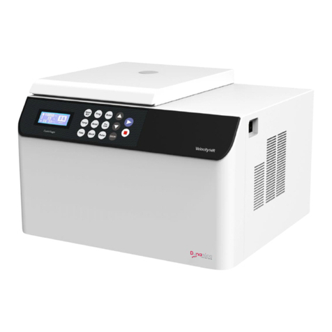
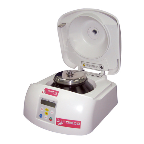
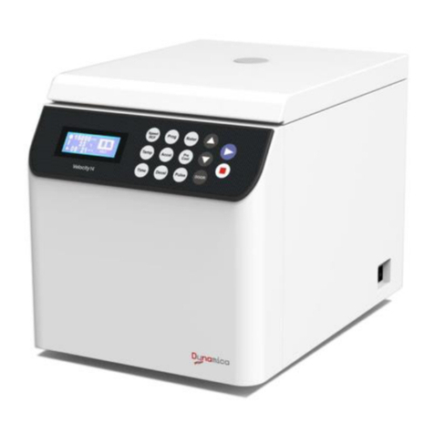
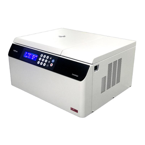
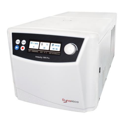
Dynamica Velocity 15HR User manual

Velocity 15HR
Micro Centrifuge
Instruction manual
Model Velocity 15HR High Speed Micro Centrifuge
Version: 1.0
Revision: D01-201802


Copyright © 2018 Dynamica Scientific Ltd.
All rights reserved. No part of this document may be reproduced or transmitted in any form or any means
without permission from Dynamica Scientific Ltd.
The names of actual companies and products mentioned herein may be the trademarks of their respective owners.
Dynamica Velocity 15HR
Refrigerated
Microcentrifuge

i
Safety Reminder
Common safety precautions
The centrifuge is designed to separate liquid-suspended materials having different
densities and particle size.
Carefully read the following safety precautions for a thorough understanding.
・Follow the instructions and procedures described in this manual to operate this
centrifuge safely.
・Carefully read all safety messages in this manual and safety instructions on your
equipment.
・Safety messages are labeled as indicated below. They are in combination with
signal words of “WARNING” and “CAUTION” with the safety alert symbol to call your
attention to items or operations that could be dangerous to you or other persons
using this equipment. The definitions of signal words are as follows:
・Do not operate this centrifuge in any manner not described in this Instruction
Manual. Should you have any troubles with this centrifuge, call a Dynamica
authorized sales/service representative.
・The precautions described in this Instruction Manual are carefully developed in an
attempt to cover all the possible risks. However, it is also important that you are
alert for unexpected incidents. Be careful when operating this centrifuge.
!
WARNING:Warning notes indicate any condition or practice, which if not
strictly observed, could result in serious injury or possible
death.
CAUTION:Caution notes indicate any condition or practice, which if not
strictly observed or remedied, could result in personal injury,
damage or destruction of the equipment.
NOTE:Notes indicate an area or subject of special merit, emphasizing
either the product’s capabilities or common errors in operation
or maintenance.
!
!
!

ii
Safety Reminder
WARNING
1. This centrifuge is not explosion-proof. Never use explosive or flammable
samples or materials that chemically react vigorously.
2. Do not install the centrifuge in or near places where inflammable gases are
generated or chemicals are stored.
3. Take all necessary safety measures before using samples that are toxic or
radioactive, or blood samples that are pathogenic or infectious. You use
such samples at your own responsibility.
1) If the centrifuge, rotor, or an accessory is contaminated by
samples that are toxic or radioactive, or blood samples that are
pathogenic or infectious, be sure to decontaminate the item
according to good laboratory procedures and methods.
2) If there is a possibility that the centrifuge, rotor, or an accessory is
contaminated by samples that might impair human health (for
example, samples that are toxic or radioactive, or blood samples
that are pathogenic or infectious), it is your responsibility to sterilize
or decontaminate the centrifuge, rotor or the accessory properly
before requesting repairs from a Dynamica authorized sales/service
representative.
3) It is your responsibility to sterilize and/or decontaminate the
centrifuge, rotor, or parts properly before returning them to a
Dynamica authorized sales/service representative.
4. Your centrifuge must be grounded properly.
5. To avoid electrical shocks, do not handle the power cord or turn on or off
the POWER switch with wet hands.
6. For safety purposes, do not go within 30 cm of this centrifuge while it is in
operation.
7. While the rotor is rotating, never forcedly release the door lock.
8. Repairs, disassembly, and other modifications to the centrifuge are strictly
prohibited unless performed by a Dynamica authorized sales/service
representative.
!
!

iii
Safety Reminder
CAUTION
1. Be careful not to get your fingers or hands caught between the door hook and the
table when closing the door. Do not insert you fingers or an object into the door hook
hole.
2. Do not move or relocate this centrifuge while the rotor is rotating.
3. Do not pour any solution such as water, detergent, or disinfectant directly into the rotor
chamber. If you do so, the bearings of the drive unit might corrode or deteriorate.
4. Before running this centrifuge, remove any dropped objects and tube fragments from
inside the rotor chamber.
5. Prevent dew drops in the centrifuge. When moving the centrifuge from the cold room
to the ordinary room, perform a) or b).
a) Warm up the centrifuge by performing the continuous operation for more than 30 minutes.
b) Place the centrifuge for more than three hours in a dried room without connecting
the power cord into the inlet of the centrifuge.
6. Cautions on rotors
1) Carefully read the rotor instruction manual before use.
2) Always check for corrosion and damage on the rotor, adapters, and tubes
before using them. Do not use the rotor, adapters, or tubes if you find such a
problem.
3) Place the rotor in position until it contacts the drive shaft. You should feel a click
when the rotor is properly placed on the drive shaft. If you do not feel anything,
there might be foreign matter stuck between the rotor and the drive shaft, and
the rotor might be tilted.Check and remove foreign matter if found.
4) Before running this centrifuge, check whether the nut for fixing the rotor to the
drive shaft and the rotor cover have been tightened firmly. If the nut has not
been tightened sufficiently, the rotor might be improperly installed and come off
during operation.
5) Do not run this centrifuge over the allowable maximum speed of the rotor,
adapters, and tubes. If their maximum speeds vary, run the centrifuge at the
lowest maximum speed among them.
6) Do not exceed the allowable imbalance. For the details, refer to section 3.1 or
the rotor instruction manual.
7) Use the rotor tubes within their actual capacities.
8) Be sure to cap the microtubes if caps are provided.
9) When using filters attached to microtubes, use microtubes specifically designed
for use with filters. If you use an ordinary microtube with a filter and the microtube
is not capped, the rotor might abnormally vibrate or come off.
10) When storing the rotor on a shelf, make sure that the shelf is secured (for
example, to avoid the rotor from dropping during an earthquake).
11) Check the chemical resistance chart attached to the rotor, and do not use any sample
inapplicable to the rotor, adapters, tubes, tube caps, etc. Using such a sample could
corrode or deteriorate such parts.
7. If you observe some abnormality in this product, stop using it immediately and
contact a Dynamica authorized sales/service representative. Notify the service
representative of the alarm code if displayed.
8. If the centrifuge will not be used for a long time, remove the power cord from the receptacle.
9. Depending on the magnitude, an earthquake might damage the centrifuge.
If you observe some abnormality, contact a
Dynamica
authorized sales/service
!
!

Contents
Page
Safety Reminder i
1. Structure 1-1
1.1
Location of the component 1-1
1.2
Operation panel 1-2
1.3
Standard accessories 1-4
2. Installation 2-1
3. Preparation 3-1
3.1
List of Applicable Rotors 3-1
3.2
Installing the rotor 3-2
3.3
Preparing samples 3-3
4. Operation 4-1
4.1
Setting the operating conditions 4-1
4.1.1
Setting the speed 4-2
4.1.2
Setting the RCF 4-3
4.1.3
Setting the running time 4-4
4.1.4
Setting the rotor temperature (Velocity 15HR) 4-4
4.1.5
Setting the acceleration and deceleration rate 4-5
4.2
Normal Operation 4-6
4.3
Programmed Operation 4-8
4.4
Spin-down Operation 4-9
4.5
Calculating Relative Centrifugal Force (RCF) 4-10
5. Other Functions 5-1
5.1
Selecting Rotor Stop Signal 5-1
5.2
Indicating the total run hours 5-2
5.3
Actual run timer 5-3
5.4
Rotor condition indicator 5-4
6. Troubleshooting 6-1
6.1
Corrective actions when alarm code is displayed 6-1
6.2
Troubleshooting when no alarm code is displayed 6-3
6.3
Opening the door during power outage 6-4
7. Maintenance 7-1
7.1
Maintenance after operation 7-1
7.2
Defrosting(Velocity 15HR) 7-2
7.3
Tubes and bottles 7-3
7.4
Service decontamination policy 7-5
8. Specifications 8-1

APPENDIX
Decontamination Sheet
WEEE Compliance
Marking for the restriction of the use of hazardous substances in electrical and electronic product (THE
PEOPLE’S REPUBLIC OF CHINA)
Rotor Guide
Rotor Instruction Manual
Warranty back cover
After-sales Service back cover

1-1
Door Hook
Drive Shaft
1. Structure
1.1 Location of the component
■Left side
Velocity 15HR
Drain hose
Cap
Door
Rotor Chamber
Operation Panel
Window of the door
*
Inlet
POWER switch
*You can measure the rotor speed through the window of the door by a optical
reflection type rotation meter.

1-2
1. Structure
1.2 Operation panel
Velocity 15HR
⑥TIME setting button
④SPEED/RCF setting button
①Acceleration rate
indicator
②
Deceleration rate
indicator ③SPEED/RCF display
⑯TEMP display
⑤TIME display
⑭OPEN button
⑮PULSE button
⑦PROG button
⑩DECEL button
⑨ACCEL button
⑫START button ⑰TEMP setting button
⑧ ♪ button
⑬STOP button
⑪DISP/CE button

1-3
1. Structure
No.
Name Function
①
Acceleration rate
indicator
Indicates the rate of acceleration from the stop to 1,000 rpm by two
LEDs.
②
Deceleration rate
indicator
Indicates the rate of deceleration from 1,000 rpm and coasting
deceleration state by three LEDs.
③
SPEED/RCF display
(1) Displays a speed or RCF setting or status value.
1)SPEED (speed indicator)
・The speed is displayed in increments of 100-rpm.
2)RCF(RCF indicator)
・The RCF is displayed in increments of 10- xg when RC
F is less
than 1,000xg.
・The RCF is displayed in increments of 100- xg when
RCF is
1,000xg or more.
(2)
Displays an alarm code if any abnormality in the centrifuge is
observed.
④
SPEED/RCF
setting button Sets the speed or the RCF. When you keep pressing this
button,
the value of the speed or the RCF changes rapidly.
⑤
TIME display
(1) Displays the setting or status value of the running time.
( Not sets the time)
・The running time is displayed in increments of 1-second when
it
is below 1 minute.
・When the running time is between 1 minute and 99minutes, it
is
displayed in increments of 1- minute .
“Hd” is displayed when the centrifuge is run continuously.
⑥
TIME setting button Sets a running time. When you keep pressing this
button, the value
of the running time changes rapidly.
⑦
PROG button Stores and recalls running conditions.
⑧
♪ button Changes rotor stop signal.
⑨
ACCEL button Sets an acceleration rate.
⑩
DECEL button Sets a deceleration rate.
⑪
DISP/CE button
(1) Shifts between the
running and the setting status and fixes the
setting value.
(2) Clears an alarm code.
⑫
START button Rotor rotation start button
⑬
STOP button Rotor rotation stop button
⑭
OPEN button
Door lock release button ( only when the rotor is stopping)
⑮
PULSE button
Accelerates the rotor while this button is pressed.
⑯
TEMP display
Displays the setting or status value of the temperature.
The temperature is displayed in increments of 1 ℃
when the
temperature is between -19℃ and 50℃.
(When the temperature is –20℃ or less, it displays “Lo”.)
⑰
TEMP setting button
Sets a temperature. When you keep pressing this
button, the value
of the temperature changes rapidly.
Temperature setting range : from “Lo”(–20℃) to 40℃.

1-4
1. Structure
1.3 Standard accessories
■The standard accessories of the Velocity 15HR centrifuge are listed in Table 1.3. Check
that all the standard accessories are provided before installation.
Table 1.3 Standard accessories for Velocity 15HR
Item name Part No. Q’ty Item drawing
Instruction manual D3-S999931 1
Power cord*
S204746
(Velocity 15HR)
(120V)
1
S204816
(Velocity 15HR)
(220-230V)
1
Tool for setting a rotor S413606 1
* The provided power cord is different depending on the country.

2-1
2. Installation
This section describes instructions that you need to follow when installing the centrifuge.
The instructions ensure your safety and maximum performance.
(1) Location
Position this centrifuge on a firm and level floor. Avoid installing it on a slippery
floor, or on a floor that conveys vibrations (for example, from people’s footsteps).
This centrifuge can be used at the ambient temperature range of 2°C to 32°C.
We recommend that this centrifuge will be used at the ambient temperature
range of 15°C to 25°C to ensure maximum performance.
Do not position this centrifuge in direct sunlight.
This centrifuge has an air-cooling system. To secure efficient cooling, keep clearances
of at least 10 cm on both sides of the centrifuge, and at least 30 cm behind it.
Do not install near a heat-generating device or water source from where water
might drip or splash. Such a location might increase the temperature of samples
or cause the centrifuge to malfunction.
Do not dew the centrifuge. When moving the centrifuge from the cold room to the
ordinary room, perform a) or b).
a) Warm up the centrifuge by performing the continuous operation for more than 30 minutes.
b) Place the centrifuge for more than three hours in a dried room without
connecting the power cord into the inlet of the centrifuge.
CAUTION:
●Before moving the centrifuge, the rotor must be removed.
!
On a firm and level floor. A room with a good ventilation
A room that is not exposed to the direct sunlight
Room temperature:
From 15
℃
to 25
℃
Humidity
From 20% to 90%
A room with no chemicals and no inflammable gas
A place where water do not drip or splash
Noncondensing
(Be careful when moving the centrifuge
from a cold room to a ordinary room.)
25℃
15
℃
90%
20%

2-2
2. Installation
This section describes instructions you need to follow when installing the centrifuge.
This instructions ensure your safety and the maximum performance.
(2) Power source
Velocity 15HR:
120 V instrument: 108-126 V AC, 15 A, 60 Hz
220-230 V instrument: 198-253 V AC, 10 A, 50 Hz ; 198-242 V AC, 10 A, 60 Hz
Install an emergency switch (circuit breaker) that turns off the main power supply
in the event of a malfunction. Optimally, install the emergency switch outside the
room or near the exit.
(3) Connection of the power cord
Connect the attached power cord to the inlet of the centrifuge.
Check that the POWER switch is turned off. Then plug in to the outlet.
(4) Removing the packing for transportation from the rotor chamber
Unlock the door by pressing the OPEN button after turning on the POWER
switch. Remove the packing for transportation from the rotor chamber after
opening the door.
WARNING:
●To avoid electrical shocks, do not touch the power cord with wet hands.
●Do not hold the cord when disconnecting the power cord from the outlet.
Hold the plug when disconnecting it.
●This centrifuge must be grounded properly.
The power cord plug has a three-prong plug. One of the three prongs is provided
for grounding. This centrifuge can be grounded just by putting the three- prong plug
into a three-prong outlet.
Do not connect the three-prong plug to a two-prong outlet using an adapter.
!
CAUTION:
●For connection to a different outlet, the power cord may be needed to be replaced.
Follow local electrical codes.
!
Velocity 15HR
Power cord
Inlet

3-1
3. Preparation
3.1 List of Applicable Rotors
Table 3.1 List of applicable rotors of the Velocity 15HR centrifuge
Rotor type
(Shape)
Maximum speed
(Maximum RCF) Tube (mL)
Allowable imbalance
Mass difference
(g)
FAS15E
(T15A61)
15,000rpm
(21,500×g) 1.5mL / 2.0mL X 24tubes 0.2 g/tube
FAS15F
(T15A62)
15,000rpm
(21,500×g)*
1.5mL / 2.0mL X 24tubes
or
0.5mL X 24tubes
0.2 g/tube***
FAS15G
(T15A63)
15,000rpm
(21,500×g)** 0.2mL X 32tubes (8-strip tubes) 0.1 g/tube
*The FAS15E rotor used with 0.5mL tube has a maximum RCF of 18,100xg.
**The FAS15G rotor has a maximum RCF of 21,500xg when a tube is loaded in the
corner tube cavity of the rotor.
***Allowable imbalance is 0.2g / tube when the same kinds of tubes are loaded in the
rotor. Allowable imbalance is 0.1g / tube when both the 1.5/2 mL micro tubes and the
0.5ml micro tubes are loaded in the rotor at the same time.
CAUTION:
● Only rotors listed in Table 3.1 can be used in the Velocity 15HR centrifuge.
● To use the rotor properly, read its instruction manual carefully.
●
Do not run the centrifuge over the allowable maximum speeds of the rotor,
adapters, tubes. Some adapters and tubes cannot withstand the speed of the rotor
in use.
● Never use any rotor and adapter that is not designated for the centrifuge by
Dynamica.
● Check the chemical resistance chart attached to the rotor, and do not use any sample
inapplicable to the rotor, the adapters, tubes, tube caps, etc. Using such a sample could
corrode or deteriorate such parts.
●If it is necessary to use commercial tubes or adapters other than those
recommended by Dynamica, contact a Dynamica authorized sales/service
representative.
!

3-2
3. Preparation
3.2 Installing the rotor
(1) Check the rotor for corrosion or crack before use. The rotor is corroded if the
surface is discolored, dented or cracked.
(2) Remove the rotor cover from the rotor and check that there is no foreign matter in tube
cavities.
(3) Place the rotor body on the drive shaft without the rotor cover. Then hold the rotor body
to avoid moving the rotor body and tighten the nut with the tool for setting rotor.
There is the mark in the side of the nut. If you can see the mark after you finish
tightening the nut, the nut has not been tightened sufficiently.
Tighten the nut sufficiently until you can not see the mark on the side of the nut.
CAUTION:
● Place the rotor in position until it contacts the drive shaft. You should feel a click when
the rotor is properly placed on the drive shaft. If you do not feel anything, there might
be foreign matter stuck between the rotor and the drive shaft, and the rotor might be
tilted.Check and remove foreign matter if found.
● When the rotor is installed improperly, the rotor may abnormally vibrate or come off .
If the nut is tightened insufficiently, the rotor may stick in the drive shaft. As the result,
the rotor may not be able to be removed from the drive shaft.
Alarm E20 and Alarm E21 may be displayed when the rotor is installed improperly.
These alarm codes are displayed when the drive shaft is rotated at high speed without
the rotor. When these alarm codes are displayed, turn off the POWER switch to clear
the alarm code.
● Be careful not to injure your fingers or hands with the threaded portion of the rotor
when holding the rotor.
!
CAUTION:
●If any abnormality such as corrosion or crack is found, stop using the rotor and
contact a Dynamica authorized sales/service representative.
!
Nut
Improper setting:
If you can see the mark
after you finish tightening
the nut, the nut has not
been tightened sufficiently.
Proper setting:
If you can not see the
mark after you finish
tightening the nut, the
nut has been tightened
sufficiently.
Tool for setting the rotor
Rotor
Drive shaft
Mark

3-3
3. Preparation
3.3 Preparing samples
(1) Prepare the sample to be centrifuged.
(2) Inject the sample into the tubes.
Balance the tubes which are loaded into the rotor symmetrically with respect to the
center of rotation of the rotor.
WARNING:
●This centrifuge and the rotor are not explosion-proof. Never use explosive or
flammable samples.
●There are restrictions on the usage of biological samples and radioactive substances
that require biological isolation such as pathogens and recombinant DNA for safety
purposes. User must prepare necessary safety measures at user’s responsibility
before treating samples containing such substances.
!
CAUTION:
・Be careful that imbalance operation may occur in the following cases. Fill the
same sample in the tubes/bottles and load them in the buckets that are placed
symmetrically with respect to the drive shaft in the rotor.
●If samples that are equal in volume but different in composition are used, the
precipitation levels may be different by centrifugation and such operation may
increase the level of imbalance.
●If samples that are equal in weight but different in volume (density) are used or if
the tubes/bottles are different in inside diameter or shape, there may be variations
in position of center of gravity and such operation may cause imbalance.
!
CAUTION:
● Use the rotor tubes within their actual capacities. Depending on the kind of tubes
used, a sample might leak from the gap between a tube and its cap if the tube is
full.
● Do not exceed the allowable imbalance. For the details, refer to section 3.1 or the
rotor instruction manual.
● Never wittingly run under unbalanced condition even though the allowable
imbalance is not exceeded.
!

3-4
3. Preparation
(3) Load the tubes into the tube cavities of the rotor.
Load the tubes which are balanced symmetrically in the step (2) into the tube
cavities.
Example of correct tube settings and incorrect tube settings
Tube
rotor
Correct settings:
Incorrect settings:
CAUTION:
●Be sure to cap the micro tubes if caps are provided, otherwise it may cause the
contamination of the sample with dust or water.
●When using filters attached to micro tubes, use micro tubes specifically designed
for use with filters. If you use an ordinary micro tubes with a filter and the micro tube
is not capped, the rotor might abnormally vibrate.
!

4-1
4. Operation
4.1 Setting the operating conditions
WARNING:
●Never open the door while the rotor is rotating or touch the rotating rotor.
●For your purposes, do not go within 30 cm of this centrifuge while it is in operation.
!
CAUTION:
● Do not place any object or your hands on the centrifuge.
● Do not push or lean against the centrifuge while it is running.
● Do not place containers holding liquid on or near the centrifuge. If they spill,
liquid may get into the instrument and damage electrical or mechanical
components.
● Do not run the centrifuge with fragments of tubes or dew drops left in the rotor
chamber. The foreign matter might get mixed with samples or might become the
cause of rise in the rotor retention temperature. Keep the interior of the rotor
chamber always clean.
● When operating the rotor at high speed after turning on the POWER switch in the
Velocity 15HR centrifuge, the temperature of the rotor chamber might increase
temporarily. However something is not wrong with the Velocity 15HR.
To cool the rotor chamber completely, wait for at least three minutes after turning
on the POWER switch.
● If this centrifuge makes peculiar sound during its operation, stop it immediately
and contact a Dynamica authorized sales/service representative.
!
NOTE:
●The setting value can be indicated by pressing DISP/CE button. By pressing it
again, the status value can be indicated.
●When changing the setting value, press the ▲ button or ▼ button (These
buttons are placed at the lower of the display) to blink the indication. If three
seconds elapses without operation, the indication does not blink and the
centrifuge does not accept the intended value. Press the ▲ button or ▼ button
again to blink the indication.

4-2
4. Operation
4.1.1 Setting the speed
① Check whether LED (color:green) at the right of the SPEED/RCF display has been
extinguished. When the LED has been extinguished, perform the step ③.
② When the LED described in step ① lights, shift the mode from the RCF indication
to the speed indication by pressing the ▼ button and ▲ button (of SPEED/RCF
setting) for 0.5 seconds or longer simultaneously (see the below). Then the LED is
extinguished and you can hear the short electronic sound.
③ Press the ▲ button or ▼ button once at the lower of the SPEED/RCF display.
■SPEED/RCF display blinks which indicates that the centrifuge is in the speed
input waiting mode.
④Press the ▼ button or ▲ button to set the intended speed.
(When pressing the button continuously, the value of the speed changes rapidly.)
■ When pressing the button, the value changes as follows.
▼ button:150 → 149 →‥‥ → 4 → 3 → 150 → 149 → ‥‥
▲ button:3 → 4 → 5 →‥‥→ 149 → 150 → 3 → 4 → ‥‥
■The speed is set in 100-rpm intervals.
⑤ Confirm the entered setting by pressing DISP/CE button.
■ Even if neglecting to press DISP/CE button, the entered setting is confirmed after
about three seconds.
extinction:the mode of the speed indication
lighting:the mode of the RCF indication
The mode is shifted by pressing two buttons
simultaneously for 0.5 seconds or longer.
×
100rpm
○×100·g
SPEED / RCF
×
100rpm
○×100·g
SPEED / RCF
Table of contents
Other Dynamica Laboratory Equipment manuals
Popular Laboratory Equipment manuals by other brands

socorex
socorex CALIBRA 852 Series operating instructions

Okolab
Okolab H201-ENCLOSURE-DMi8-LASERSAFE-158 Assembly manual

Emerson
Emerson Daniel Danalyzer 1000 Hardware reference manual

WelVac
WelVac 200 manual

Sutter Instrument
Sutter Instrument Lambda DG-4 Operation manual

DEMA
DEMA 163CH installation instructions