Diesella 18560120 User manual

18560120
User/Technical Manual
Contents subject to change without notice
Version 1.0
07/2017

CONTENTS
1. INTRODUCTION and INSTALLATION............................................................................................1
General and Safety Information ................................................................................................................................. 1
Specifications ......................................................................................................................................................... 1
Contents ................................................................................................................................................................ 2
Load Cell Wiring ...................................................................................................................................................... 2
Installation ............................................................................................................................................................. 2
2. OVERVIEW OF CONTROLS AND FUNCTIONS ..................................................................................3
Indicator Display Character Definitions........................................................................................................................ 3
Indicator Display ..................................................................................................................................................... 4
Function Keys ......................................................................................................................................................... 4
3. OPERATIONS ......................................................................................................................5
Normal Weighing Mode............................................................................................................................................. 5
ZERO..................................................................................................................................................................... 5
Setting a Tare Weight ............................................................................................................................................... 5
Hold Function ......................................................................................................................................................... 5
4. Calibration .........................................................................................................................6
5. View ADC Code or Power Voltage ..............................................................................................7
6. Configuration Parameters Setup...............................................................................................8
7. Details about RS232...........................................................................................................12
8. Symbol Definitions:.............................................................................................................14
9. Trouble shooting:...............................................................................................................15

.1
1.
General and Safety Information
INTRODUCTION and INSTALLATION
Risk of Electrical Shock: Disconnect all power sources before making cable connections to the scale
platform or indicator.
For use in dry environments only.
Do not operate in hazardous areas.
Read and understand all operating instructions before using this product. Keep this manual for future reference.
Record the weight shortly after placing a load on the platform. After extended periods, the load cell’s output signal
Place the scale on a hard, flat, and level surface before using.
may
result in a less accurate reading.
Avoid extended exposure to extreme heat or cold. Optimum operation is at normal room temperature. See operating
temperature range in the specifications table. Allow the scale to acclimate to room temperature before using.
Allow sufficient warm up time. Turn the scale on and allow up to 2 minutes for internal components to stabilize before
weighing.
Electronic scales are precision instruments. Do not operate near cell phones, radios, computers or other electronic
devices that emit radio frequencies that may cause unstable readings.
Avoid using in heavy vibration or heavy airflow conditions.
Specifications
Model
18560120
Max Capacity
120 kg / 250 lb
Readability
0.02 kg / 0.05 lb
Display Resolution
1:6000
Construction
Epoxy painted carbon steel, stainless steel platform
Weighing Units
kg /lb / lb:oz
Calibration unit
kg
Application Modes
Weighing
Display
16.5mm (0.65”) 7-segment LCD, 51/2 digits, with blue backlight
Zero Range
+20% of full capacity
Tare Range
Full capacity
Stabilization Time
<3 seconds
Operating Temp.
40° to 105°F (5° to 40°C)
Humidity Range
<90% relative humidity, non-condensing
Power supply:
Alkaline Batteries: 4 x “AAA” size cells
AC Adapter: 9Vdc/600mA, with central positive
Interface
RS232
Feet
Adjustable height
Safe Max Overload
150% of capacity
Indicator Dimensions
162x80x29mm (L x W x H)
Base Dimensions
305 x 305 x 75mm (L x W x H) (Feet is adjusted to the maximum height)

.2
Contents
Indicator
Scale Platform
DC9V 600mA Power Adapter
Outer Hexagonal Wrench
Owner’s Manual
Load Cell Wiring
PIN1----Red, Excitation +
PIN2----Black, Excitation –
PIN3----Green, Signal -
PIN4----White, Signal +
Installation
1. Remove the scale from the packaging and place it on a work table with the feet facing up. Remove the shipping
protection screw. See below pictures.
2. Place the scale on a hard, flat, and level surface.
3. Adjust the feet to level the scale.
4. Install the batteries or plug in the adapter. Now the scale is ready for use.
.3
2. OVERVIEW OF CONTROLS AND FUNCTIONS
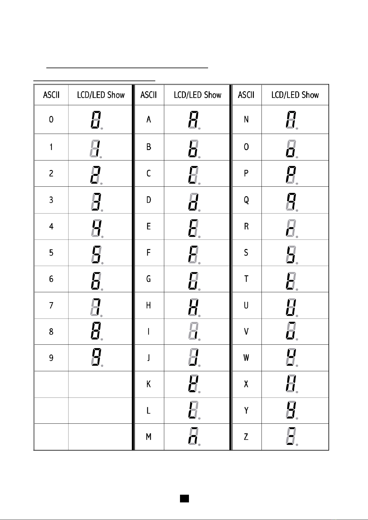
Indicator Display Character Definitions

.4
Indicator Display
ZERO- Scale is zeroed and gross weight is 0, tare is 0.
TARE - Display reading is net weight; tare is not 0.
lb, kg, oz - Unit of measure.
Hold - Scale is in dynamic weighing mode.
-Hold flashes - actual fluctuating weight is displayed.
-Hold does not flash - locked weight is displayed
Function Keys
KEY
MODE
DEFINITION
UNIT/HOLD
Weighing mode <3 seconds Enter or exit HOLD mode
>3 seconds Select units of measure
Setup or Calibration mode Change the digit on flashed position and click this button
to add 1
Displaying A/D code or input voltage
mode
Choose the weight inner code or input working voltage to be
displayed.
TARE
Weighing mode Tare the weight
Setup or Calibration mode Confirm the input data and continue to next step
Displaying A/D code or input voltage
mode Choose filtered or un-filtered weight A/D data
ON/OFF/ZERO
Weighing mode <3 seconds Zero the platform weight
>3 seconds Power off the scale
Setup or Calibration
mode/Displaying A/D code or input
voltage mode
Exit to normal weighing mode
ON/OFF/ZERO
+UNIT/HOLD
Weighing mode
(more than 3 seconds) Enter user parameter setup mode
ON/OFF/ZERO
+TARE
Weighing mode
(more than 3 seconds) Enter calibration mode
ON/OFF/ZERO
+TARE
+UNIT/HOLD
Weighing mode
(more than 3 seconds)
Go to Show A/D code or input working voltage of indicator
mode

.5
3. OPERATIONS
Normal Weighing Mode
1. Power on the scale by pressing the ZERO/ON/OFF k ey.
2. When the display stabilizes, but it doesn’t show zero, press ZERO/ON/OFF to set a new zero point.
3. Place objects on the scale platform and read the weight on the indicator.
Note: Objects should be placed at the center of the platform. Corner or side loading heavy objects may risk
overloading an individual load cell and damage the scale.
Yes
No
No
4. To change the weight unit of measure, press and hold the UNIT/HOLD key for 4 seconds.
5. Power off the scale by pressing and holding the ZERO/ON/OFF key for 4 seconds.
ZERO
If the display dose not shows 0, and there is nothing on the platter, press the ZERO/ON/OFF key to zero the reading.
Zero range: ±20% * full Capacity.
The zero function is unavailable when the displayed reading is out of the zero range and the indicator will show the
error message 0____ or 0ˉ ˉ ˉ ˉ, meaning the scale is over or under zero range.
Setting a Tare Weight
1. Zero the scale as described above.
2. Place an empty container on the platform, press the TARE key. The display will return to zero, eliminating the weight
of the container. The TARE announciator will be lit on the display.
3. Put the material or object to be weighed in the container. The net weight will be displayed.
4. To exit tare mode, remove all weight from the scale. The display will show a negative weight. Press the TARE key to
return the display to zero.
Hold Function
The Hold function is being used if you like to hold the results at the display after the weight/load has been removed from
the scale.
1. Press HOLD key while scale is under load.
2. “HOLD” announciator is being displayed at the screen.
3. The weight remains saved in the display after unloading the scale.
4. For deactivation of the Hold function, press again the UNIT/HOLD key.

.6
4. Calibration
Note:
(1) Before calibrating the scale, you should prepare standard weights (more than 10% of FS weight) for
calibration.
(2) In the following steps, pressing ZERO/ON/OFF will exit calibration.
1. Move all weight from the scale. Under normal weighing mode, press and hold TARE and ZERO/ON/OFF keys for
more than 4s to enter calibration mode.
2. The indicator will show “CAL-?”, which means the scale is ready for calibration. Press the TARE key to confirm
and continue into calibration mode.
3. When “CAL.P0” is displayed, the scale will begin to calibrate the zero-point of the scale. Remove all weight from
the scale. Press the TARE key to confirm, or press the ZERO/ON/OFF to exit this mode. After receiving the
reasonable zero-point data, the next step will automatically occur.
4. When “CAL.P1” is displayed, the scale will be calibrated on second calibration point. xxxxxx kg (or lb) will be
displayed. The default standard weight is 50%FS. Load 5%-100%FS weight on the scale, and use the UNIT/HOLD
keys to input the loaded weight. Press the TARE key to confirm the input, and then the indicator will flash the input
standard weight. After the scale becomes stable and receives the ADC’s data corresponding to the standard
weights, and if the data is reasonable and acceptable, the indicator will automatically be directed to next step. If the
second point cannot be calibrated correctly, it will display “CAL.Er” and return back to step3 for re-calibration.
5. When “CAL.P2”is displayed, the scale will be calibrated on third calibration point. xxxxxx kg (or lb) will be
displayed. The default standard weight is 100% FS. Load 10%-100%FS (this must be equal or larger than the
weight from the second calibration point) weight on the scale. Use the UNIT/HOLD keys to input the standard
weight’s value. Press the TARE key to confirm. The indicator will flash the input weight. If the indicator receives
reasonable data, it will go to next step automatically. If an error occurred, the scale will display “CAL.Er” and
return back to step3 for re-calibration.
6. When “CAL.P0” is shown again, the scale will calibrate the zero-point again. Remove any weight from the scale,
press the TARE key to confirm; the displayed data will flash. If the indicator receives reasonable data, it will
calculate and store all parameters into EEPROM. Then it will auto-reset, and be directed to weighing mode. If an
error occurred in calibration, the scale will display “CAL.Er” and then it necessary to repeat the procedure from
step3.
.7
5. View ADC Code or Power Voltage
1. In normal weighing mode, press and hold UNIT/HOLD , TARE and ZERO/ON/OFF keys until “code” is shown,
which means the indicator is working under display inner code mode. In this mode, you can examine the inner
working voltage, the stability of weighing system, the variety value of A/D data as per the loaded weight.
NOTE:
1) The increment of ADC code for FS weight must be larger or equal to 2 times of selected display division;
otherwise, the calibration cannot be properly completed. E.g. the display division is 0.1kg. Load 100kg
standard weight on the platform, the increment of A/D code is at least 2x 100kg/0.1kg= 2x1000=2000. In
this case, the scale can be calibrated. Otherwise, smaller division need to be chosen.
2) The data should be stable; otherwise, the calibration cannot properly complete.
2. In this mode, you can calculate the proper ADC data at zero point by examining the A/D data for loaded weight. If
the ADC increase for full capacity is NFS, the power-on zero range is set to Zp% FS and zero key range is set to
Zk% FS. Then the proper ADC data of zero point is larger than (Zp%+ Zk%) x NFS.
3. ADC increase for full capacity (NFS) can be calculated by: Load the weight W on the platform, and the ADC increase
for W weight is Nw. The ADC increase for full capacity WFS is (NFS)= (Nw)x (WFS)/W .
Negative value may be displayed because of error connect of loadcell or error position of the zero-point
potentiometer on PCB; however, the software only deals with positive value. So, is you are the position of zero-point
potentiometer is error; adjust potentiometer’s position to make the ADC data will be positive value and larger than
(Zp%+ Zk%) x NFS. Normally the indicator is factory-calibrated, and end users do not need this operation.
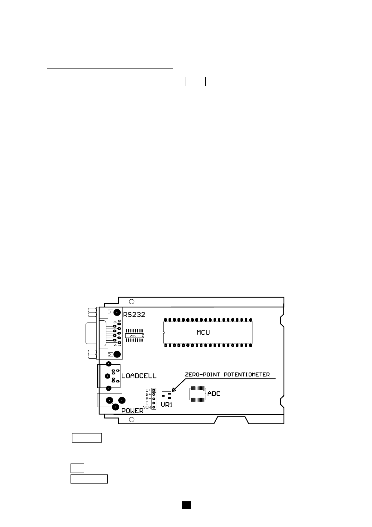
Below is the drawing of position of the zero-point potentiometer on PCB for conference, decrease ADC data by
rotating clockwise, and increase ADC data by rotating counter-clockwise.
4. Press the UNIT/HOLD key to select displaying weight inner code or input the inner working voltage value. When
“Ux.xx” is displayed, the display digit is voltage value, and the unit is V. The proper working power voltage is
between 5V to 8 V.
5. Press the TARE key to display filtered or un-filtered weight A/D data; when is on, the data is filtered.
6. Press the ZERO/ON/OFF key to exit this mode and return to normal weighing mode.

.8
6. Configuration Parameters Setup
1. When the scale is off, press and hold ZERO/ON/OFF and UNIT/HOLD keys until ‘SEtUP’ is shown, which
indicates that the scale is in Configuration parameter setup mode.
2. During setup mode, press the UNIT/HOLD key to change the flashed digits. Press the TARE key to confirm the
flashed digits. Press the ZERO/ON/OFF key to exit this mode.
3. Summary of Configuration Parameters Setting:
Para-
meter
Default
Setting
18560120
Factory Setting
P1.xy 5 Auto-off time: no auto-off;
01-15 minutes auto-off time 5
P2.xy 02
0=no hold function; 1=hold lager weight reading; 2-
50= unchangeable reading
when the variety is within +
2~50d ,auto release hold function when weight is
below 10d and auto-hold new stable weight (more than 10d);
1
P3.x 3
0=no RS232 function;
1=continuously output display data;
2= continuously output gross, TARE and net weight;
3=output display data one time when scale is stable;
4=output gross, TARE and net weight one time when scale become stable;
5=Bio-RS232;
6= continuously output display data use five numbers;
7= output display data use five numbers when scale is stable;
1
P4.x 3
Baud rate for RS232: 0=1200bps, 1=2400bps, 2=4800bps, 3=9600bps,
4=19200bps 3
P5.x 0 RS232 format: 0=8N1, 1=7O1, 2=7E1 0
P6.xy 5
Resolution select:
00=500, 08=2400, 16=7500, 24=35000,
01=600, 09=2500, 17=8000, 25=40000,
02=750, 10=3000, 18=10000, 26=50000,
03=800, 11=3500, 19=12000, 27=60000,
04=1000, 12=4000, 20=15000, 28=70000,
05=1200, 13=5000, 21=20000, 29=75000,
06=1500, 14=6000, 22=25000, 30=80000,
07=2000, 15=7000, 23=30000, 31=100000
14
P7.x 0 Division select: 0=1, 1=2, 2=5 1

.9
Para-
meter
Default
Setting
18560120
Factory Setting
P8.x 0 Decimal point in calibration: 0= x1, 1= x0.1, 2= x0.01;
3= x0.001; 4=
x0.0001; 5= x10 2
P9.x 0 Calibration unit: 0=kg, 1=lb 0
P10.x 3
Weighing units enable:
0=only kg; 4=kg or lb:oz;
1=only lb; 5=lb or lb:oz;
2=only lb:oz; 6=kg, lb, or lb:oz
3=kg or lb;
3
P11.x 7
Power-on zero-point range:
0=calibration zero -point +1%FS;
1=calibration zero -point +2%FS;
2=calibration zero-point +5%FS;
3=calibration zero-point +10%FS;
4=calibration zero-point +20%FS;
5=calibration zero-point +50%FS;
6=calibration zero-point +100%FS;
7=No limitation
7
P12.x 6
Zero range for ZERO button:
0= Power-on zero-point +1%FS;
1= Power-on zero-point +2FS;
2= Power-on zero-point +3FS;
3= Power-on zero-point +4FS;
4= Power-on zero-point +5%FS;
5= Power-on zero-point +10%FS;
6= Power-on zero-point +20%FS;
7= Power-on zero-point +50%FS;
8= Power-on zero-point +100%FS;
9= No limitation
4
P13.x 0
Weight signal
is in
power-
on zero point range, Choose which data as current
power-on zero point:
0= current weight ;
1= calibration zero-point;
2=switch-off zero-point
0
P14.x 3
Weight signal
is not in
power-
on zero point range, Choose which data as current
power-on zero point:
0= current weight ;
1= calibration zero-point;
2=switch-off zero-point;
3=continuously display “0ˉˉˉˉ”
1
P15.x 6
Zero tracking range:
0=0d, no tracking;
1=+0.25d; 2= +0.5d; 3=+1d; 4=+1.5d; 5=+2d; 6=+
3d;
7= +4d; 8=+5d
4
P16.x 2 Data filter intensity: 0=very weak, 1=weak, 2=middle, 3=strong 2

.10
Para-
meter
Default
Setting
PS-105-120
setting
P17.x
Default
Setting
PS-105-120
setting
1
Setting
PS-105-120
setting
Check weight stability range: 0=+0.5d; 1=±1d; 2=+1.5d; 3=+
2d;
4=+3d; 5=+4d; 6=+5d; 7=+6d; 8=+7d; 9=+8d
18560120
Factory Setting Setting
PS-105-120
setting
1
P18.x 1
Overload limit range: 0=FS+0d; 1=FS+9d; 2=101%FS;
3=102%FS; 4=105%FS; 5=110%FS; 6=120%FS; 7=150%FS;
8=200%FS; 9=No limitation 1
P19.X 2
Backlight on-off mode selection (if it is installed):
0= Backlight is always off;
1= Backlight is always on;
2= Backlight is auto on and auto off. It is auto off after 10s when scale goes to
stable and has no key operation, and it is auto on when scale is unstable or
there’s some key operation.
2
4. Some Detailed Explanation
P3.x: RS232 mode setting
P3.0: No RS232 function. It will not transmit or receive any data although the scale is with RS232 hardware. RS232
function can be only activated when scale is in normal weighing mode.
P3.1: Continuously output of the current displayed reading and unit, and it does not receive any data.
The output format is as below:
<LF>< reading, minus, decimal point, weight unit><CR><EXT>
P3.2: Continuously output of the current gross weight, TARE weight and net weight reading data including unit, and
not accept any data. The format is as follows:
<LF><Gross: reading, minus, decimal point, unit><CR><EXT>
<LF> <TARE: reading, decimal point, unit><CR><EXT>
<LF> <Net: reading, minus, decimal point, unit><CR><EXT>
The number of position used: weight reading ---7; Minus ---1;
Decimal point ---1; Weight unit ---2 or 4;
P3.3: When the scale is stable, it will output the current displayed weight reading automatically one time including
unit, and not accept data. The output format is same as P3.1
P3.4: When the scale is stable, it will output the current gross weight, TARE weight and net weight data including
unit automatically one time, and not accept data. The output format is same as P3.2
P3.5: Bio-RS232 data output.
P3.6: Continuously output of the current net weight in gram with five numbers. The output format is as below:
<LF>< x x x x x><CR><EXT>
If net weight is larger than range, “>>>>>”will be transmitted, and If net weight is below 0, “-----”will be
transmitted.
P3.7: When the scale is stable, it will output the current net weight in gram with five numbers. The output format is
same as P3.6.
P9.x: Calibration unit
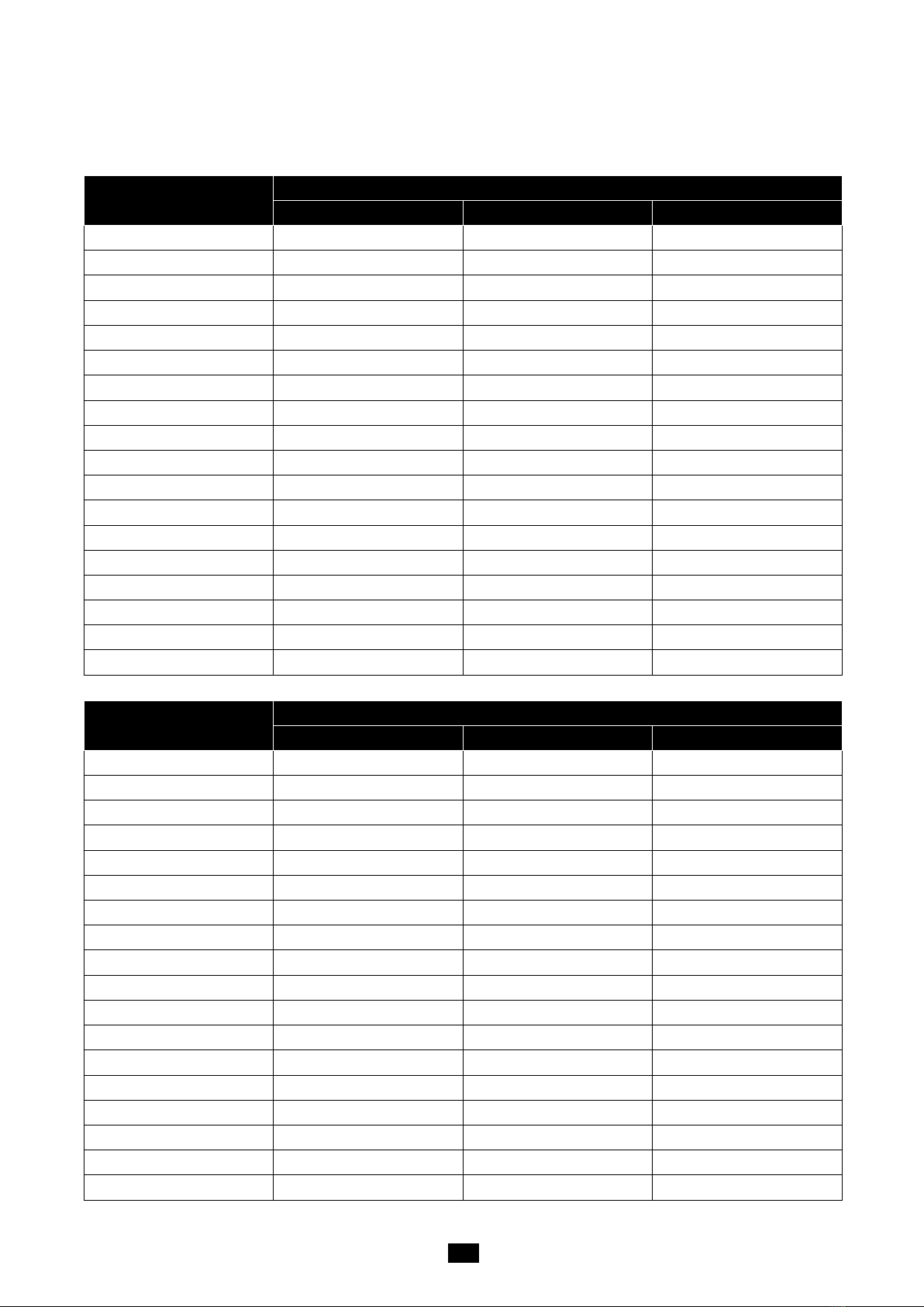
As per the setting of P7, P8 and P9, following table is listed,
.11
Table1: use Kg as calibration unit:
Calibration division value Display division value in different weight unit that can be used
kg lb lb:oz
0.0001kg 0.0001kg 0.0002lb Not available
0.001kg 0.001kg 0.002lb Not available
0.01kg 0.01kg 0.02lb 0.5oz
0.1kg 0.1kg 0.2lb 5 oz
1kg 1kg 2lb Not available
10kg 10kg 20 lb Not available
0.0002kg 0.0002kg 0.0005 lb Not available
0.002kg 0.002kg 0.005 lb 0.1 oz
0.02kg 0.02kg 0.05 lb 1 oz
0.2kg 0.2kg 0.5 lb Not available
2kg 2kg 5 lb Not available
20kg 20kg 50 lb Not available
0.0005kg 0.0005kg 0.001 lb Not available
0.005kg 0.005kg 0.01 lb 0.2 oz
0.05kg 0.05kg 0.1 lb 2oz
0.5kg 0.5kg 1 lb Not available
5kg 5kg 10 lb Not available
50kg 50kg Not available Not available
Table2: use LB as calibration unit:
Calibration division value Display division value in different weight unit that can be used
Kg lb Lb:oz
0.0001lb Not available 0.0001lb Not available
0.001 lb 0.0005 kg 0.001 lb Not available
0.01 lb 0.005 kg 0.01 lb 0.2 oz
0.1 lb 0.05 kg 0.1 lb 2 oz
1 lb 0.5 kg 1 lb Not available
10 lb 5 kg 10 lb Not available
0.0002 lb 0.0001 kg 0.0002 lb Not available
0.002 lb 0.001 kg 0.002 lb Not available
0.02 lb 0.01 kg 0.02 lb 0.5 oz
0.2 lb 0.1 kg 0.2 lb 5 oz
2 lb 1 kg 2 lb Not available
20 lb 10 kg 20 lb Not available
0.0005 lb 0.0002 kg 0.0005 lb Not available
0.005 lb 0.002 kg 0.005 lb 0.1 oz
0.05 lb 0.02 kg 0.05 lb 1 oz
0.5 lb 0.2 kg 0.5 lb Not available
5 lb 2 kg 5 lb Not available
50 lb 20 kg 50 lb Not available

.12
P10.x: Select the weighing unit that may be chosen by pressing UNIT/HOLD.
P12.x: Zero range for ON/OFF/ZERO button operation
If zero key can be activated, it can clear the TARE weight. If zero point is above the setting range, the indicator
will show “0ˉ ˉ ˉ ˉ”, and if zero point is below the setting range, “0_ _ _ _” will be shown.
P15.x: Zero tracking range
Choose the zero tracking range as per the stability of weighing system, accuracy and weight excursion. The
normal setting is +0.5d ~ +1.5d.
P16.x: Data filter intensity
The larger the chosen digit is, data filter intensity is stronger, and the speed of data updating is lower.
P17.x: Range of weight stability checking
If the variety of weight reading is within the setting range continuously for several times, the scale is
recognized as stable. The normal setting is +1d ~ +3d.
P18.x: Overload range that can be displayed (when weight is larger than range, “ˉˉˉˉˉ”will be shown):
7. Details about RS232
7.1 RS-232 connects between scale and Host:
Scale ------------------------------------------Cable--------------------------------------Host
(DB9 female)-------------------(DB9 male)----(DB9 female)----------------------(DB9 male)
TXD 2 -------------------------- 2 ------------------------ 2 -----------------------------2 RXD
RXD 3 -------------------------- 3 ------------------------ 3 -----------------------------3 TXD
GND 5 -------------------------- 5 ------------------------ 5 -----------------------------5 GND
DSR 4 -------------------------- 4 ------------------------- 4 ----------------------------4 DTR
DTR 6 -------------------------- 6 ------------------------- 6 ----------------------------6 DSR
CTS 7 -------------------------- 7 -------------------------- 7 ----------------------------7 RTS
RTS 8 -------------------------- 8 -------------------------- 8 ----------------------------8 CTS
NC 1 -------------------------- 1 -------------------------- 1 ----------------------------1
NC 9 -------------------------- 9 -------------------------- 9 ----------------------------9
Note: The indicator DB9 female’s pin4 and pin6 is shorted, pin7 and pin8 is shorted!
7.2 When P3 is set to 5:
7.2.1) The baud rate and data format is fixed as per P4 and P5 setting. Responses to serial commands will be
immediate, or within one weight measure cycle of the scale. One second should be more than adequate
for use as a time-out value by remote (controlling) device.
7.2.2) The length of the weight field will be 7 digit weight data, one for minus sign, one for decimal point, two for
measure unit (e.g. “lb”, “kg”). If the unit is lb:oz, another two for “lb” and one for a space (<sp>) after
lb. Units of measure abbreviations are always lower case.
7.2.3) If the weight is overcapacity, the scale will return nine ‘^’ characters (the field of minus sign, decimal point,
weight data is filled by ‘^’).
If the weight is under capacity, it will return nine ‘_’ characters (the field of minus sign, decimal point, and
weight data is filled by ‘_’).

.13
If the zero point is error, it will return nine ‘_’ characters.
7.2.4) The character will be ‘-’ for negative weight or a space character for positive weight. Minus sign follows after
the first digit.
7.2.5) Useless leading zero before digits is suppressed.
7.3 Key to symbols used
<LF> Line Feed character (hex 0AH)
<CR> Carriage Return character (hex 0DH)
<ETX> End of Text character (hex 03)
<SP> Space (hex 20H)
H1H2H3 Three status bytes
<p> Polarity character including minus sign for negative weight and a pace character for positive
weight
W1-W7 weight data
<dp> decimal point
U1U2 measure units, kg, lb, or oz
7.4 Commands and response
7.4.1 Command: W<CR> (57h 0dh)
Response:
①<LF>^^^^^^^^^u1u2<CR><LF>H1H2H3<CR><ETX>---over capacity
②<LF>________u1u2<CR><LF> H1H2H3 <CR><ETX>---under capacity
③<LF>---------u1u2<CR><LF> H1H2H3<CR><ETX>---zero-point error
Note: If the weight unit is lb: oz, U1U2= oz in above item ①②③.
④<LF><p>w1w2w3w4w5w6<dp>w7u1u2<CR><LF>H1H2H3<CR><ETX> ---
Scale is stable, and the current weight unit is kg or lb. With or without decimal point and the position is
as per the P9 setting and current unit.
⑤<LF><p>w1w2w3w4w5lb<sp>w6w7<o><z><CR>H1H2H3<CR><ETX> or
<LF><p>w1w2w3w4lb<sp> w5w6<dp>w7oz<CR>H1H2H3<CR><ETX> ----
The current unit is lb: oz.
7.4.2 Command: S<CR> (53h 0dh)
Response: <LF> H1H2H3<CR><ETX>
7.4.3 Command: Z<CR> (5ah 0dh)
Response: <LF> H1H2H3<CR><ETX>
Zero function is activated and it returns to current scale status. Just like pressing ON/OFF/ZERO button,
If ZERO function cannot be activated, it will return to current scale status.
7.4.4 Command: T<CR> (54h 0dh)
Response: <LF> H1H2H3<CR><ETX>
TARE function is activated, and then returns scale status. Just like pressing TARE button, If TARE
function cannot be activated, it will return to current scale status.
7.4.5 Command: U<CR> (55h 0dh)
Response: <LF>u1u2<CR><LF> H1H2H3<CR><ETX>
Changes units of measure and return scale status with new units, just like pressing UNIT/HOLD button.
The new measure unit should be allowed to use as per P10 setting. If weight unit is lb:oz, u1u2= “lb oz”
.14
7.4.6 Command: L<CR> (4ch 0dh)
Response: <LF> H1H2H3 <CR><ETX>
If Hold function can be activated, it will enable/disable hold (lock) function, like the UNIT/HOLD key is
pressed, and returns scale status.
7.4.7 Command: X<CR> (58h 0dh)
Response: power off the scale, just like press down the ON/OFF/ZERO key to turn off the scale.
7.4.8 Command: all others
Response: <LF>? <CR><ETX>
Unrecognized command
7.5 Output status bit meaning:
The status bit definition:
Bit Byte 1 (H1) Byte 2 (H2) Byte 3 (H3)
0 0=stable 0= not under capacity 01=normal work mode
10= hold work mode
00=not define
11= not define
1= not stable 1= under capacity
1 0= not at zero point 0= not over capacity
1= at zero point 1= over capacity
2 0=not AD over 0=not Zero Over 0= gross weight
1=AD over 1=Zero Over 1= net weight
3 0= eeprom OK 0=not Zero down 0=not AD down
1= eeprom error 1= Zero down 1=AD down
4 always 1 always 1 always 1
5 always 1 always 1 always 1
6 always 0 always 1 always 0
7 parity Parity parity
8. Symbol Definitions:
0ˉ ˉ ˉ ˉ Zero point is over the setting range
0_ _ _ _ Zero is below the setting range
Adˉ ˉ ˉ ADC is over max. range;
Ad _ _ _ ADC is below min. range;
ˉ ˉ ˉ ˉ ˉ Weight signal is too large
_ _ _ _ Weight signal is too small
EEP.E0 The EEPROM can’t be accessed;
EEP.E1 The parameters are not same with backup data;
EEP.E2 The setting parameter(s) is not in normal range;.
CAL-PxScale’s calibration point;
CAL.Er There is an error in calibration
Hold(H) Hold function is active.
Net ◄The display reading is net weight
Zero ◄The scale is at zero point
CAP.-- The the setting full capacity will be displayed
.15
d.-- The division will be displayed
Px.y The No. x parameter is set to y.
Lo.bAt The voltage of batteries or input power is below 4.7V
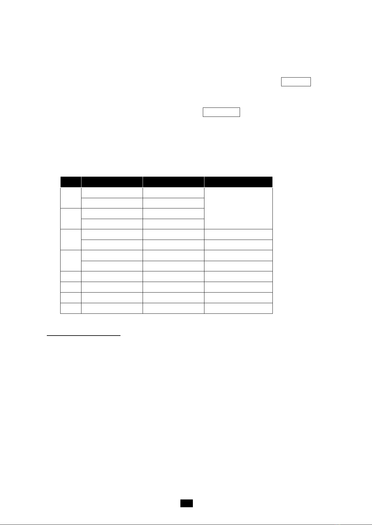
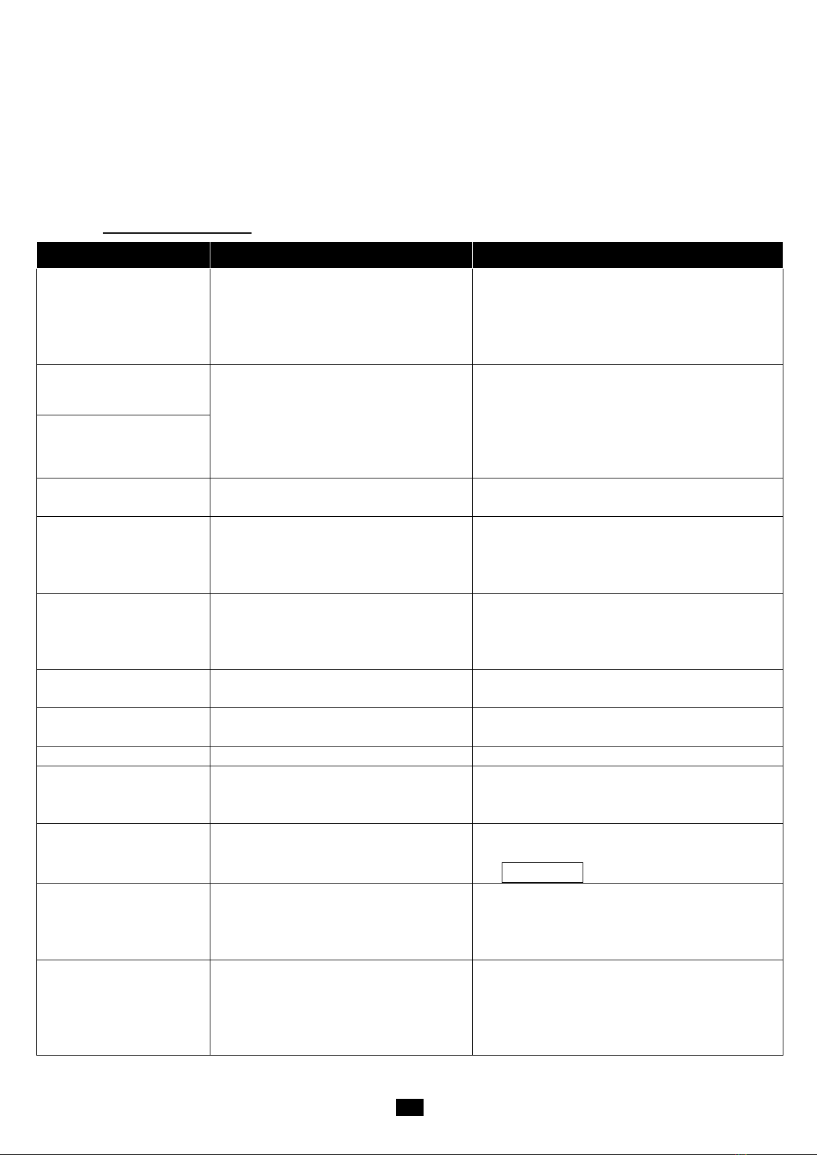
9. Trouble shooting:
SYMPTOM
PROBABLE CAUSE
REMEDY
Does not turn on.
1. AC adapter is not securely connected
2. Low battery
3. Indicator is damaged
1.
Re-plug the AC adapter or rotate the plug to
securely connect to the scale
2. Replace the batteries
3. Replace with a new indicator & perform
calibration
Adˉ ˉ ˉ
1.
The cable from platform to indicator is
not correctly connected, or
disconnected, or short circuit
2. Indicator is damaged
3. Load cell cable is broken
4.
Load cell is damaged
1. Check the cable or replace with a new cable
2. Replace with a new indicator and perform
calibration.
3. Return the scale for repair
Ad_ _ _
0ˉ ˉ ˉ
Indication is out of key zero range
Reduce weight on platter till indication is within key
zero range.
0_ _ _
Weight reading below Power On Zero limit.
1.
Loosen the shipping protection screws
2. Check whether an object is stuck between scale
base, if yes, remove the object.
3. Perform zero calibration.
ˉ ˉ ˉ
1.
Weight reading exceeds Overload limit
2. The weight value cannot be displayed in
the current unit of measure because it
exceeds 6 digits.
1. Reduce load on the scale until a weight value is
displayed.
2. Use a more appropriate unit of measure.
_ _ _
Weight reading below Under load limit
1.
loose the shipping protection screws
2. Perform zero calibration
EEP.E1
The parameters are not same with backup
data
Re-set Setup parameters as technical manual
instructed.
EEP.E2
Setting parameter(s) is not in normal range
Re-set USER parameters per the Technical manual
CAL.Er
1.
Input data or loaded weight is too small,
too big
2.
Weight signal is unstable, un-linear
1.
Input correct data, load correct weight onto
platform.
2.
Return the scale for repair
Cannot zero the display
1.
Load on scale exceeds allowable limits.
(20%FS)
2. Load on the scale is unstable
1.
Remove load from the scale.
2. Wait for the load to stabilize. then press the
ZERO/ON/OFF
key to zero the display
1. Max. CAPACITY not same
as marked on overlay
2. Any function invalid
3. Any units missed
CONFIG and USER parameters are not
correctly set
Re-set CONFIG and USER parameters per the
Technical manual
Weighing is not accurate
1. An object is stuck between the load cell
and scale base
2. Load cell received a heavy impact
1.
Remove the object
2. Perform Linearity calibration
3. Loose the shipping protection screws.
4. Place the load on the center of the weighing
platform
Table of contents


