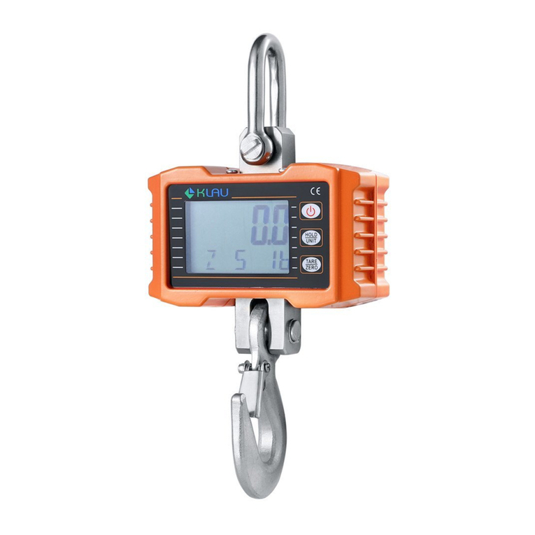
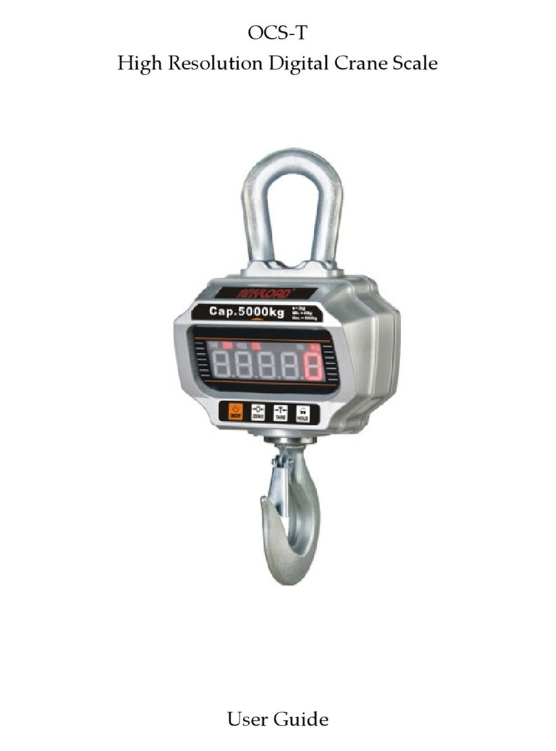
Anyload OCS Series User manual

OCS Series
Electronic Crane Scale
OCSA3 & OCSA4 General Purpose Crane Scales
OCSB3 & OCSB4 Compact Crane Scales
OCSC3 & OCSC4 Enhanced Crane Scales
OCSG1 & OCSG2 Heat Resistant Crane Scales
OCSM1 & OCSM2 Light Duty Crane Scales
OCSZ Heavy Duty Crane Scale
TECHNICAL
MANUAL


2 | ANYLOAD OCS Series Electronic Crane Scale Technical Manual
TABLE OF CONTENTS
1. User Input 3
Keys on Scale 3
Keys on Remote Controller 3
2. Advanced Operations 4
Auto Zero Range 5
Manual Zero Range 5
Zero Tracking Range 6
Acceleration due to Gravity 6
User-Defined Unit 7
Calibration 7
System Unit 10
Maximum Capacity 11
Zero Weight Calibration 11
One Load Calibration 12
Two Loads Calibration 13
Three Loads Calibration 14
Power Adjustment Mode 16
3. RS-232 Communication 17
4. Messages Illustration 21
5. Appendix 22

3 | ANYLOAD OCS Series Electronic Crane Scale Technical Manual
1. User Input
In this section, the operator will learn how to operate the scale properly
either on scale or by its remote controller.
KEYS ON SCALE
ON/OFF
ZERO
TARE
HOLD
2ND
Scale Configuration
Exit
↑
→
Confirm
Save
Calibration
Exit
↑
→
Confirm
Save
Power Adjustment
Exit
↑
→
Confirm
System Info
Exit
Confirm
KEYS ON REMOTE CONTROLLER
Scale
Configuration
Calibration
Power
Adjustment
System Info
↑
↑
↑
→
→
→
Confirm
Confirm
Confirm
Confirm
↓
↓
↓
←
←
←
Exit
Exit
Exit
Exit
Save
Save

4 | ANYLOAD OCS Series Electronic Crane Scale Technical Manual
2. Advanced Operations
Operations section features the versatile and powerful functions for crane
scale measurement. Most of the operations are accessible via dedicated
remote controller. Some of the settings in the scale are protected by
password to prevent unwanted settings modification. If you are not sure to
do it, contact your local representative or dealership for technical support.
Action
oTo enter SCALE CONFIGURATION MODE, press 2ND key on scale
or on remote controller twice. The password message will
display.
oTo input SCALE CONFIGURATION password, use ZERO and TARE
keys on scale or and on remote controller.
oTo confirm the password or inputted value, press HOLD keys on
scale or on remote controller.
oTo save and exit SCALE CONFIGURATION MODE, press 2ND key on
scale or on remote controller.
oTo exit SCALE CONFIGURATION MODE without saving, press ON/OFF
key on scale or on remote controller.
To learn more how to input values or change the option, refer to User Input
section in User’s Guide.
Function
oIn SCALE CONFIGURATION MODE, user can change the scale’s
metrology performance, like system measurement unit, auto and
manual zero, automatic zero‐tracking, anti‐motion algorithm, and
gravidity acceleration, etc.
oThe screen will display the welcome message:

5 | ANYLOAD OCS Series Electronic Crane Scale Technical Manual
Condition
oThe scale must not in HOLD mode otherwise an error message
will display.
AUTO-ZERO RANGE
oDuring the power‐on procedure, the initial load on the scale will be
automatically zeroed if the load is within the AUTO‐ZERO RANGE.
oThere are 6 options of AUTO‐ZERO RANGE: “0%, “2%”, “4%”,
“10%”, “20%”, and “100%”of Max. Cap.. When AUTO‐ZERO RANGE
is set to “0%”Max. Cap., the AUTO‐ZERO function is disabled.
oThe default AUTO‐ZERO RANGE is set to “20%” Max. Cap..
MANUAL-ZERO RANGE
oAfter powering on, the scale can be zeroed manually by pressing ZERO
key on scale or on remote controller if the load’s weight is in
MANUAL‐ZERO RANGE. Some models do not have zero key on scale,
use the remote controller instead.
oThere are 6 options of MANUAL ‐ZERO RANGE: “0%, “2%”, “4%”,
“10%”, “20%”, and “100%”Max. Cap.. When MANUAL ‐ZERO RANGE
is set to “0%” Max. Cap., the MANUAL ‐ZERO function is disabled.
oThe default MANUAL ‐ZERO RANGE is set to “4%” Max. Cap..
WARNING:
Parameters in SCALE CONFIGURATION are closely related to scale’s metrology
performance. It is NOT recommended to change anything in SCALE
CONFIGURATION unless you are authorized from your local representative or
dealership with the correct password.

6 | ANYLOAD OCS Series Electronic Crane Scale Technical Manual
ZERO-TRACKING RANGE
oZERO‐TRACKING function will zero the scale when weight reading is
within the ZERO‐TRACKING RANGE.
oThere are 6 options of ZERO‐TRACKING RANGE: 0.0 division, 0.5
division, 1.0 division, 1.5 division, 2.0 division, and 2.5 division
equivalent to “0E”, “0.5E”, “1.0E”, “1.5E”, “2.0E”, and “2.5E”,
respectively. When ZERO‐TRACKING RANGE is “0.0E”, the
ZERO‐TRACKING function is disabled.
oThe default ZERO‐TRACKING RANGE is set to 0.5 division, “0.5E”
ACCELERATION DUE TO GRAVITY
oAdjust the GRAVITY ACCELERATION only when you use the scale in a
place where acceleration of gravity is greatly different from the place
where the scale was calibrated.
oGRAVITY ACCELERATION can be set from “9.700”to “9.899”.
oThe default GRAVITY ACCELERATION is set to “9.794”.
NOTE:
Enabling Zero-Tracking will enhance temperature and drift performance of the scale

7 | ANYLOAD OCS Series Electronic Crane Scale Technical Manual
USER-DEFINED UNIT
oThe scale allows user to define a special unit as USER‐DEFINED UNIT.
oUSER-DEFINED UNIT can be set from “0.000” to “9.999”.
oThe default USER‐DEFINED UNIT is set to “1.000”.
oAfter pressing 2ND key on scale or on remote controller, the scale
will save current settings and will exit from SCALE CONFIGURATION
MODE then automatically returns to WEIGHING MODE.
CALIBRATION
Action
oTo enter CALIBRATION MODE, press 2ND key on scale or on
remote controller twice. Some models do not have 2ND key on
scale, use the remote controller instead. Enter the password for
calibration. (Note, this procedure should be done by qualified or
authorized person to change the calibration settings. Ask the
password from your local dealership or from technical support).
NOTE:
A USER-DEFINED UNIT is an additional unit represents the unit defined by the user,
aside from kg or lb. The conversion value is equivalent to the ratio against to its
SYSTEM UNIT.
For example, assuming the scale’s system unit is kg. If the USER-DEFINED UNIT
is equivalent to 1.234 unit per 1kg then after switching to USER-DEFINED UNIT,
the scale should display the 1000kg weight to 1234 user-defined unit.

8 | ANYLOAD OCS Series Electronic Crane Scale Technical Manual
oTo input CALIBRATION password, press ZERO and TARE keys on scale or
and on remote controller.
oTo confirm the password, press HOLD key on scale or on remote
controller.
oTo save and exit CALIBRATION MODE, press 2ND key on scale or
on remote controller.
oTo exit CALIBRATION MODE without saving, press ON/OFF key on scale
or on remote controller.
To learn more on how to input values or change the option, refer to User Input
section in User’s Guide.
NOTE:
To meet some countries’ metrology requirements, a Calibration plug is
equippedwhichwillbeusedtoswitchthescalefromweighingmodeto
calibrationmode.
UponenteringtheCalibrationmode,amessage maydisplayin
thescreen.This meansthatyouneedtoswitch thejumperofthecalibration
plug. Refertothesampleimagesforthemainboardof someofOCSmodels
andlocatethecalibrationjumperpinandtheinstructionstoswitchthejumper.
Inthismodel,theusermusttakeoffthefrontpaneltoaccesstheplug.
Afterthecalibration,putthejumperbacktoitsoriginalpin.
Ifyourmodeldoesnothavecalibrationplug,justenterthecalibrationpassword
andproceedwiththecalibrationprocess.

9 | ANYLOAD OCS Series Electronic Crane Scale Technical Manual
Function
oWhen the scale needs to be recalibrated, user can recalibrate the
scale in CALIBRATION MODE.
oThe screen displays the welcome message:

Condition
oThe scale must not in HOLD mode otherwise, error message
will display.
NOTE:
It is NOT recommended to do the CALIBRATION unless you are authorized from
your local representative.

10 | ANYLOAD OCS Series Electronic Crane Scale Technical Manual
SYSTEM UNIT
oIn contrast to the DISPLAY UNIT, the SYSTEM UNIT was set before it
leaves the factory. It was set when the scale was calibrated at factory.
oSome models were set to metric scale’s SYSTEM UNIT (kg by
default) while some were set to imperial scale’s SYSTEM UNIT
(lb by default).
To switch between metric and imperial system, refer to the Display Unit Switch
section.
oThe lb indicator w i l l light on after SYSTEM UNIT switches
to lb.
oThe kg indicator will light on after SYSTEM UNIT switches to
kg.
Note: Some models may not have both lb and kg indicator. Some may have lb
indicator or kg indicator only. For models with only one indicator, the light will
turn off when the scale is switch to its alternate measurement unit (either in
kg or lb).
NOTE:
SYSTEM UNIT shall be changed only if the alternate unit will be made
as the new system unit. Most of these scales are calibrated from
factory with imperial unit (lb unit) as the system unit. If you want to
use the metric as the system unit, change the system unit to Un PG
then recalibrate the scale. Recalibration is required for changing
SYSTEM UNIT.
The same process if your scale was set with metric system unit,
switch the system unit to Un Lb then recalibrate.

11 | ANYLOAD OCS Series Electronic Crane Scale Technical Manual
MAXIMUM CAPACITY
Action
oTo set the scale’s MAXIMUM CAPACITY, select the capacity options.
The parameter value will be multiplied by 1000 to get the maximum
capacity value. For example, if it is set to FS 2 ( see image below) then
the scale will be set to have 2000 lb or 2000kg max capacity (it will not
matter what unit you set at system unit).
ZERO WEIGHT CALIBRATION
Action
oWhen the screen displays , this means that we
have to start the zero calibration. Remove the load from
scale except for hooks or chains that will be used to hold
the test weight. Keep the scale unloaded, stabled and
relatively at zero weight.
oAfter pressing HOLD key on scale or on remote controller, the
scale will detect current weight, displaying the below detection
message.
WARNING:
Do NOT try to set maximum capacity bigger than the scale’s actual
capacity. Overloading may damage and break the scale. It is also dangerous
and it may cause injury or fatality.

12 | ANYLOAD OCS Series Electronic Crane Scale Technical Manual
oZERO WEIGHT CALIBRATION is finished when message
is displaying.
ONE LOAD CALIBRATION
Action
oPut on the test weight, when the screen displays .
oAfter pressing HOLD key on scale or on remote controller,
the scale displays the below message, waiting for user’s input of
the load’s weight value.
oAfter pressing HOLD key on scale or on remotecontroller, the
scale will detect the load’s weight and will display the below detection
message.

13 | ANYLOAD OCS Series Electronic Crane Scale Technical Manual
oONE LOAD CALIBRATION is finished when message
is displaying. To finish the calibration, press 2ND key on scale or on
remote controller.
Condition
oThe load must be heavier than “0”, (or “0.0” or “0.00”, depending on
the resolution) otherwise an error message will
display.
oThe load must not be heavier than the scale’s maximum capacity
otherwise an error message will display.
TWO LOADS CALIBRATION
Action
oPut on the second weight, when the screen displays.
oAfter pressing HOLD key on scale or on remote controller, the
scale displays the first load’s weight value, waiting for user’s input of
the second load’s weight value.
NOTE:
It is recommended to use test weight or span calibration weight that is
equal to scale’s maximum capacity in calibrating the scale.
NOTE:
In most cases, one load calibration is enough but if high linearity
performance of the scale is required then calibrate the scale using the multi
load calibration like Two Loads Calibration or Three Loads Calibration.
.

14 | ANYLOAD OCS Series Electronic Crane Scale Technical Manual
oAfter pressing HOLD key on scale or on remote controller, the
scale will detect the second weight and will display the below detection
message.
oTWO LOADS CALIBRATION is finished when message
is displaying. To finish the calibration, press 2ND key on scale or
on remote controller.
Condition
oThe second load must be heavier than the first load otherwise an error
message will display.
oThe second load must not be heavier than the scale’s maximum
capacityotherwise an error message will display.
THREE LOADS CALIBRATION
Action
oPut on the third weight, when the screen displays
oAfter pressing the HOLD key scale or on remote controller, the
scale displays the second load’s weight value, waiting for user’s input of the
third load’s weight value.
NOTE:
If the scale will be calibrated with two loads, it is recommended to use a first
test weight of 50% of scale’s maximum capacity and then 100% of scale’s
maximum capacity for the second test weight.

15 | ANYLOAD OCS Series Electronic Crane Scale Technical Manual
oAfter pressing HOLD key on scale or on remote controller, the
scale will detect the third weight and will display the below detection
message.
oTHREE LOADS CALIBRATION is finished when the below message
is displaying. The scale will exit CALIBRATION MODE automatically and
will return to WEIGHING MODE.
Condition
oThe third load must be heavier than the second load otherwise an
error message will display.
oThe third load must not be heavier than the scale’s maximum capacity
otherwise an error message will display.
NOTE:
If the scale will be calibrated with three loads, it is recommended to use a first test
weight of 33% of scale’s maximum capacity, 66% of scale’s maximum capacity for
the second and then 100% of scale’s maximum capacity for the third.

16 | ANYLOAD OCS Series Electronic Crane Scale Technical Manual
POWER ADJUSTMENT MODE
Action
oTo enter POWER ADJUSTMENT MODE, press 2ND key on scale
or on remote controller twice.
oTo input POWER ADJUSTMENT password, press ZERO and TARE
keys on scale or and on remote controller.
oTo confirm the password, press HOLD key on scale or on
remote controller.
oTo save and exit POWER ADJUSTMENT MODE, press 2ND key on
scale or on remote controller.
oTo exit POWER ADJUSTMENT MODE without saving, press ON/OFF key
on scale or on remote controller.
To learn more on how to input values or change the option, refer to User Input
section in User’s Guide.
Function
oSystem power needs to be adjusted when the scale is reset manually.
User can adjust the system voltage in POWER ADJUSTMENT MODE.
oThe screen displays the welcome message:
oAfter pressing HOLD key on scale or on remote controller, the
scale displays current system voltage (or 6.50V if the scale has been
reset), waiting for user’s input of new voltage.

17 | ANYLOAD OCS Series Electronic Crane Scale Technical Manual
oAfter pressing HOLD key on scale or on remote controller, the
scale will save the new voltage and will return to WEIGHING MODE.
3. RS-232 Communication
The scale is equipped with a RS‐232 serial input/output port which is intended
for interfacing scoreboards, desktop indicator, hand‐held data collector,
computer, etc.
COMMUNICATION WAYS
oThere are two options for communicating the scales and digital
peripherals. Either in cabled or wireless way. For cabled way, the
peripherals can be connected to the scale’s full duplex communication
port (optional) while for via wireless, the peripherals can communicate
to the scale through its half‐duplex wireless port (optional).
oCable connection distance is up to 15 meters. Plug one end of the
9‐pin D‐type connector into the RS‐232 socket at the rear of scale.
Plug another end of the connector to your peripherals that support
RS‐232 communication.
oFor wireless, the scale can work with peripherals over 500 meters on a
condition that there is no obstruction between them.
RS-232 PROTOCOL
oThe scale sends out data in the format of string. A string is consisting of
10 bytes, 1 byte for start flag, 1 byte for scale address, 5 bytes for LED
data, 1 byte for indicator data and 1 byte for check sum, shown below:

18 | ANYLOAD OCS Series Electronic Crane Scale Technical Manual
Byte
ASCII
Default Value
flag of start
0x7F
0x7F
address of scale
user defined
0x00
data of LED1
according to display
data of LED2
according to display
data of LED3
according to display
data of LED4
according to display
data of LED5
according to display
data of indicator
according to display
check sum
according to all data
Flag for start is always fixed at 0x7F.
Scale address is defined at SCALE ADDRESS in COMMUNICATION SETUP.
Default address is set to 00 (0x00 in hexadecimal).

19 | ANYLOAD OCS Series Electronic Crane Scale Technical Manual
LED data is defined as below
Other manuals for OCS Series
1
This manual suits for next models
11
Table of contents
Other Anyload Scale manuals

Anyload
Anyload OCS-T User manual

Anyload
Anyload NPS Series Manual

Anyload
Anyload EB300 User manual

Anyload
Anyload ES-HA Series User manual

Anyload
Anyload ES-HB Series User manual

Anyload
Anyload EC200 User manual

Anyload
Anyload OCS-S Series User manual

Anyload
Anyload EB100 User manual

Anyload
Anyload EC100 User manual

Anyload
Anyload OCS Series User manual