manuals.online logo
Brands
  1. Home
  2. •
  3. Brands
  4. •
  5. geo-FENNEL
  6. •
  7. Measuring Instrument
  8. •
  9. geo-FENNEL FET 405K User manual

geo-FENNEL FET 405K User manual

USER MANUAL
www.geo-fennel.com
EN
FET 405K / FET 420K
FET 402K-L
2
EN
Contents
1. Supplied with A
2. Power supply B
3. Keypad and functions C
4. Operation D
5. Safety notes E
Dear customer,
Thank you for your condence in us having purchased a geo-FENNEL instrument.
This manual will help you to operate the instrument appropriately.
Please read the manual carefully - particularly the safety instructions. A proper use only guarantees a
longtime and reliable operation.
geo-FENNEL
Precision by tradition.
SUPPLIED WITH
A
· Elektronic Theodolite FET 405K / FET 420K / FET 402K-L
· Battery and charger
· Container
· User manual
FEATURES
· 2 large easy to read LCDs
· Simultaneous reading of horizontal and vertical circle
· Illumination of display and eld view
· Clockwise / anti-clockwise horizontal angle reading
· „0“ set or hold of horizontal circle at any position
· „V“ circle reading in gon / degrees or in % slope
Additional feature of FET 402K-L:
· Coaxial, focusable laser beam integrated to the telescope
3
EN
Technical data
Magnication 30 x
Clear objective aperture 45 mm
Shortest focusing distance 1,4 m
Angle measurement inkremental
Accurady
· FET 402K-L 0,6 mgon (2“)
· FET 405K 2 mgon (10“)
· FET 420K 4 mgon (10“)
Minimum reading
· FET 402K-L 0,2 mgon (1“)
· FET 405K 1 mgon (5“)
· FET 420K 2 mgon (10“)
Compensator Two-axis compensator
Measuring units 400 gon / 360° / mil
Optical plummet 3 x
Focusing range 0,5 -
∞
Plate level 30“ / 2 mm
Circular level 8‘ / 2 mm
Operating time / power supply 35 h NiMH / 40 h Alkaline
Temperature range -20°C up to + 50°C
Dust / water protection IP 54
Tribrach detachable
Weight 4,0 kg
Variant technical data of FET 402K-L
Target focusable
Laser class 3R
Beam diameter 500 / 100 m
Maximum visibility 180 m
Devation 5“
Operating time / power supply:
Theodolite and laser 24 h NimH / 30 h Alkaline
Temperature range -20°C up to + 45°C
Weight 4,5 kg
4
EN
POWER SUPPY
B
BATTERY REPLACEMENT
Power o󰀨 the instrument and remove the battery case.
Press down the hook of the battery box and remove the cover.
Charge the battery outside of the instrument and insert it again when fully charged.
Alternatively: Insert new alkaline batteries.
Close the cover and insert the battery box again.
RECHARGE THE BATTERY
Remove the battery box from the instrument and insert the plug of the charger into the charging socket
of the battery box.
RED LIGHT at the charger indicates that the batteries are being charged.
GREEN LIGHT at charger indicates that the batteries have been fully charged.
Before rst use of the instrument fully charge the rechargeable batteries.
BATTERY STATUS INDICATION
The battery symbol on the display shows the current battery status.
Full power
E󰀨ective
Still e󰀨ective
Low power but e󰀨ective; replace the alkaline battery / recharge NiMH battery pack.
The instrument will power o󰀨 automatically shortly. Replace the alkaline battery /
recharge the NiMH battery pack immediately.
5
EN
C
KEYPAD AND FUNCTIONS
NOMENCLATURE (2)
1. Fixing screw for handle
2. Laser
3. Focusing knob
4. Telescope eyepiece
5. Horizontal tangent screw
6. Horizontal clamp knob
7. Display
8. Instrument center mark
9. Optical plummet
10. Plummet eyepiece
11. Circle vial
12.Foot screw
NOMENCLATURE (1)
1. Handle
2. Objective lens
3. Optical sight
4. Laser button
5. Plate vial
6. Battery box
7. Vertical tangent screw
8. Vertical clamp knob
9. Operating keys
10. Base locking button
11. Tripod base plate
6
EN
Button
FUNC
REP
HOLD
V/%
R/L
0SET
Δ
Δ
Δ
Function
Optional function keys
Display and crosshair illumination
Repeated angle measurement
HOLD the horizontal angle
Vertical angle display
Vertical angle / percent display
Left/right horizontal angle measurement
OSET of the horizontal angle
ON/OFF switch
Move the cursor leftward
Move the cursor rightward
Change the ashing digit
DISPLAY INDICATION
1. Ht Total value of repeated measure-
ments
2. V Vertical angle
3. Number of repeated measure-
ments
4. AVG Average of repeated measure-
ments
5. HR Right horizontal angle
6. HL Left horizontal angle
7. TILT TILT compensator function
8. F Optional function keys
9. G Angle unit GON
10. % Vertical grade %
11. REP Status of repeated measurement
12.BAT Battery status indication
If the display shows “b” after activating the TILT compensation function, which means exceeded com-
pensation range, the instrument should be set on a more even surface.
7
EN
OPERATION D
PREPARATION FOR THE MEASUREMENT
· Tripod
Place the tripod legs to a suitable length and tighten the locking clamps. Make sure that the tripod
has been set up safely.
· Mount the instrument
Monut the instrument onto the tripod carefully, and x it with the 5/8“ retaing bolt of the tripod.
· Adjust the vials
First adjust the ciruclar vial, then adjust the plate vial. The plate vial has been adjusted correctly and
the instrument is leveled perfectly if the plate vial stays centered no matter in which direction the
instrument is rotated.
· Ground point centering
The ground point can be targeted with the built-in optical plummet. Focus the target with the eypiece
of the optical plummet and focus the ground point with the focussing ring.
POWER ON THE INSTRUMENT
· Press the POWER button for 1 sec.
· The manufacturer code will be displayed (short). The buzzer
will sound. Now the instrument is ready for use.
· The vertical angle indication will show the current value.
· Rotate the telescope 360° to activate the vertical measuring
mode and to activate the keypad.
TILT CORRECTION FUNCTION
This theodolite is equipped with a TILT compensator. The TILT angle of the instrument will be compen-
sated automatically by the device. If the instrument is tilted too much “b” will be shown on the display
which means the instrument exceeds the compensator range. Level the instrument more precisely (for
activation / de-activation see (SETTING METHODS).
8
EN
VERTICAL ANGLE SET
Press the button „FUNC“
Press the button „V%“
Display indication „F1“
Press the button „O-SET“
Display indication „Step 1“ rst rotation (A)
Conrm the adjustment via collimator with „O-SET“
Rotate
Display indication „Step 2“ second rotation (B)
Conrm the adjustment via collimator with „O-SET“
MODE CONVERSION OF THE HORIZONTAL RIGHTWARD (HR) AND
LEFTWARD (HL) TURNING INCREMENT
Aim at target “A” using the crosshair of the telescope. Press the R/L key,
transform the horizontal angle mode HR into the mode HL. Measuring with
mode HL.
The R/L key is of no e󰀨ect to the vertical angle.
Press the R/L key again, transform the mode HL into the mode HR.
HORIZONTAL ANGLE OSET (OSET)
Aim at target A using the crosshair of the telescope. Press the 0SET key
once to set the reading of the horizontal angle 0°00’ 00”:
The 0SET key is only e󰀨ective for the horizontal angle.
The horizontal angle can be set 0 at any time except in the HOLD mode
(HOLD key).
9
EN
HORIZONTAL ANGLE LOCKED - UNLOCKED
· Turn the tangent knob and place the required horizontal angle.
· Press the HOLD button to hold the current value of the horizontal angle. The value will ash while
this function is active.
· Press the HOLD button again to release the value.
SLOPE PERCENT MODE (%)
· In the angle mode the vertical angle can be transformed into percent of grade.
· Press the button „V%“ to switch from the vertical angular measurement shown in degrees into per-
cent.
· The maximum % value will be 99.999 %; exceeding this display will show „- - - - -“.
ANGULAR REPEATED MEASUREMENT
1. Press the FUNC key.
2. Press the REP key to enter into the repeated mode.
3. Aim at target A and press the 0SET key once to set the rst target
reading 0°00’ 00”.
4. Turn the horizontal tangent knob to aim at the second target B.
5. Press the HOLD key to hold the horizontal angle and store in the
instrument.
6. Turn the horizontal tangent knob to aim at target A again. Press
the R/L key to release the angle and keep the status.
7. Turn the horizontal tangent knob to aim at the target B again.
8. Press the HOLD key to hold the horizontal angle and store in the
instrument. Double and average angle-value will be shown in
the display.
9. Repeat the steps 7 and 8 according to the measurement require-
ments.
10. To return to the standard angular measurement press the FUNC key,
then press HOLD key.
· The reading of the horizontal angle could reach max. ±2000°00’ 00”
when measuring in the „Plate left” or “Plate right” mode. The ve-seconds
reading could reach at least ±1999°59’ 59”.
· The repeated measurement should be limited to15 times.
· In case the deviation of two measurements exceeds or equals ±30
Error E04 will be shown in the display. Then press button OSET and
start a new measurement.
10
EN
SOUND FUNCTION (AT 90° / 100GON)
If required select the sound function to conrm passing 0 / 100 / 200 / 300 / 400gon (0°, 90°, 180°,
270°) when the collimating section rotates (see chapter SETTING METHODS).
AUTOMATIC SHUT-OFF
The automatic shut o󰀨 can be selected when the instrument is not in permanent use.
Available intervals: 10 to 30 minutes (see chapter SETTING METHODS).
ILLUMINATION OF DISPLAY AND CROSSHAIR
In dark surroundings and at unfavourable light conditions the display and crosshair can be illuminated:
Power on the illumination:
Press the button „FUNC“ - „F“ will be displayed -
press the button „FUNC“ again - the illumination is now powered on.
Power o󰀨 the illumination:
Press the button „FUNC“ - „F“ will be displayed -
press the button „FUNC“ again - the illumination is now powered o󰀨.
DISTANCE MEASUREMENT USING THE STADIA METHOD
A distance measurement can be carried out by using the crosshair.
· Read the levelling rod.
· Aim the instrument‘s telescope at the levelling
rod.
· Mulitply the value of the distance „d“ between
the two stadia hairs with 100.
· The result „D“ = the distance from the in-
strument centre to the levellig rod (D = d x 100).
11
EN
USE OF THE LASER
(only model FET 402K-L)
With the built-in laser beam the target can be aimed at and marked. By focussing the laser dot can be
adjusted. Such, the marking of the target can be acomplished by one person only.
The laser beam is pulsed and can therefore be used together with any geo-FENNEL receiver for rota-
ting lasers. Thus, FET 402K-L can be applied for any task that would require the use of a rotating laser.
Power on the laser beam with the laser key.Turn the laser key to adjust the brightness of the laser
beam.
The smallest diameter of the laser dot will be achieved if the laser beam is focussed.
By means of the laser beam all measuring tasks can be acomplished and will be visualized to the user.
INITIAL SETTING
The instrument supplies multi-functions for your selection to meet the di󰀨erent requirements of
measuring conguration.
ITEM
1
2
3
4
5
6
Change between
10“ and 20“
Conrm every 90°
by signal tone
Change between DEG
(degree), GON, MIL
Set interval for auto-
matic shut-o󰀨
Set „o“ point of
vertical angle
Set incline correction
function
Minimum
reading
Quadrant
signal tone
Unit of angle
measurement
Auto shutt-o󰀨
Measuring mode
for vertical angle
Automatic
compensation
PRAMETER SET-
TING
Setting 0
1“
Setting 0
o󰀨
Setting 0/DEG
Setting 1/GON
Setting 0/O󰀨
Setting 1/10 min.
Setting O
Setting 1
Setting 2
Setting 0
O󰀨
Setting 1
5“
Setting 1
on
Setting 2/MIL
Setting 2/20 min.
Setting 3/30 min.
Vertical angle
(0 in horizontal)
Zenith angle
(0 in zenith)
Height angle +/-
(0 in horizontal)
Setting 1
On
Setting
10“
12
EN
FACTORY SETTINGS
Minimum reading
Quadrant signal tone
Unit of angle measurement
Automatic shut-o󰀨
Vertical angle measuring mode
Automatic compensation
Data transmission
1“
OFF
GON
OFF
ZENITH ANGLE
OFF
OFF
SETTTING METHODS
Power on the instrument.
Press „FUNC“ and then the ON/OFF key.
Press the buttons and to select the required values (1 -
7).
The parameters set will be available until the next parameter
setting - even if the instrument is powered o󰀨.
Δ
Δ
Numbers 1 to 7
ERROR DISPLAY
DISPLAY
B
E00
E01
E02
E03
E04
E05
E06
ERROR DESCRIPTION AND DISPOSAL
The vertical compensator is out of the compensating range. Level the instrument
again.
The collimate rotation is too fast. Press the 0SET key to set 0. If “E00” is
shown again the instrument needs to be repaired.
The telescope turning is too fast. Press the V/% key to set 0 for the vertical plate
specication.
Interior error of the horizontal angle measuring system. Power on the instrument
again. If the error is shown again the instrument needs to be repaired.
Interior error of the vertical angle measuring system. If the error is shown again
the instrument needs to be repaired.
Di󰀨erence between every value exceeding 30“ during the angle repeated mea-
surement. Press the 0SET key and measure repeatedly.
The number of angle repeated measurement exceeds 15. Press key and measure
repeatedly.
Errors during the process of vertical angle 0set or adjusting 0set when the clamp
angle to the horizon exceeds 45°. Adjust repeatedly.
13
EN
E
SAFETY NOTES
INTENDED USE OF INSTRUMENT
Triangle, polygon and engineer measurements in the eld of civil engineering as well as cadastral
survey.
CARE AND CLEANING
Handle measuring instruments with care. Clean with soft cloth only after any use. If necessary damp the
cloth with some water. If the instrument is wet clean and dry it carefully. Pack it up only if it is perfectly
dry. Transport in original container / case only.
SPECIFIC REASONS FOR ERRONEOUS MEASURING RESULTS
Measurements through glass or plastic windows; dirty laser emitting windows; after the instrument has
been dropped or hit. Please check the accuracy.
Large uctuation of temperature: If the instrument will be used in cold areas after it has been stored in
warm areas (or the other way round) please wait some minutes before carrying out measurements.
ELECTROMAGNETIC ACCEPTABILITY (EMC)
It cannot be completely excluded that this instrument will disturb other instruments (e.g. navigation sys-
tems); will be disturbed by other instruments (e.g. intensive electromagnetic radiation nearby industrial
facilities or radio transmitters).
CE-CONFORMITY
The instrument has a CE mark according to EN 55011: 2007, EN 61000-6-1-2007.
WARRANTY
This product is warranted by the manufacturer to the original purchaser to be free from defects in mate-
rial and workmanship under normal use for a period of two (2) years from the date of purchase. During
the warranty period, and upon proof of purchase, the product will be repaired or replaced (with the same
or similar model at manufacturers option), without charge for either parts or labour. In case of a defect
please contact the dealer where you originally purchased this product. The warranty will not apply to this
product if it has been misused, abused or altered. Without limiting the foregoing, leakage of the battery,
bending or dropping the unit are presumed to be defects resulting from misuse or abuse.
14
EN
SAFETY INSTRUCTIONS
· Do not operate the laser without rst reading and understanding all the safety and technical data in
the user manual.
· Do not stare into the laser beam or point it towards people or animals.
· Do not aim the beam at reective surfaces such as windows or mirrors as reected beams can be
dangerous.
· The laser should only be operated by trained and qualied personnel. All users should be fully
informed about the potential biological e󰀨ects on the eyes and skin when using laser devices and be
conversant with laser protection regulations - as per IEC 60825-1:2014.
· Laser products should be restricted from persons under 18.
· In the event of a class 3R laser beam hitting the eye immediately close your eyes and turn your head
away from the beam.
· Do not attempt to repair or adjust the laser device.
· The emitted laser radiation is potentially dangerous to the eye.
· The use of class 3R laser products may require registration with a local authority and the appoint-
ment of a laser protection o󰀩cial.
· Do not operate the laser without rst reading and understanding all the safety and technical data in
the user manual.
· The user manual must always be kept with the instrument.
· The instrument should be kept from unauthorized use.
· Areas where these class 3R laser devices are being used should display the appropriate warning
signs. This is to prevent unauthorized persons inadvertently entering the working area. If necessary,
ensure that the laser working area is being guarded and/or shielded. The limitation of laser radiation
in controlled areas avoids eye injuries to external persons.
· The legal requirement for using class 3R laser product will vary from country to country. The user is
responsible for compliance to national standards and regulations.
· Non-observance may lead to injuries.
LASER CLASSIFICATION
(MODEL FET 402K-L only)
The instrument is a laser class 3R lroduct according to
DIN IEC 60825-1:2014.
Please observe the instructions give above when using the
instrument.
The instrument is marked with class 3R warning labels.
Laser
3R
IEC 60825-1:2014
P ≤ 5 mW @ 635 - 670 nm
www.geo-fennel.de
15
EN
EXCEPTIONS FROM RESPONSIBILITY
1. The user of this product is expected to follow the instructions given in the user manual. Although all
instruments left our warehouse in perfect condition and adjustment the user is expected to carry out
periodic checks of the product’s accuracy and general performance.
2. The manufacturer, or its representatives, assumes no responsibility of results of a faulty or intentional
usage or misuse including any direct, indirect, consequential damage, and loss of prots.
3. The manufacturer, or its representatives, assumes no responsibility for consequential damage, and
loss of prots by any disaster (earthquake, storm, ood etc.), re, accident, or an act of a third party
and/or a usage in other than usual conditions.
4. The manufacturer, or its representatives, assumes no responsibility for any damage, and loss of
prots due to a change of data, loss of data and interruption of business etc., caused by using the
product or an unusable product.
5. The manufacturer, or its representatives, assumes no responsibility for any damage, and loss of
prots caused by usage other than explained in the user manual.
6. The manufacturer, or its representatives, assumes no responsibility for damage caused by wrong
movement or action due to connecting with other products.
geo-FENNEL GmbH
Kupferstraße 6
D-34225 Baunatal
Tel. +49 561 / 49 21 45
Fax +49 561 / 49 72 34
[email protected]
www.geo-fennel.de
All instruments subject to technical changes.
Precision by tradition.
08/2018

This manual suits for next models

2

Other geo-FENNEL Measuring Instrument manuals
geo-FENNEL TOTALSTATION FTS 300 User manual

geo-FENNEL

geo-FENNEL TOTALSTATION FTS 300 User manual

geo-FENNEL EcoDist Plus User manual

geo-FENNEL

geo-FENNEL EcoDist Plus User manual

geo-FENNEL FHT 100 User manual

geo-FENNEL

geo-FENNEL FHT 100 User manual

geo-FENNEL FL 220HV User manual

geo-FENNEL

geo-FENNEL FL 220HV User manual

geo-FENNEL FLM 400 Data User manual

geo-FENNEL

geo-FENNEL FLM 400 Data User manual

geo-FENNEL EL 515 User manual

geo-FENNEL

geo-FENNEL EL 515 User manual

geo-FENNEL FL 40-Pocket II User manual

geo-FENNEL

geo-FENNEL FL 40-Pocket II User manual

geo-FENNEL FKL 50 User manual

geo-FENNEL

geo-FENNEL FKL 50 User manual

geo-FENNEL FL 510HV-G TRACKING User manual

geo-FENNEL

geo-FENNEL FL 510HV-G TRACKING User manual

geo-FENNEL FHM 10 User manual

geo-FENNEL

geo-FENNEL FHM 10 User manual

geo-FENNEL FLG 6X-GREEN User manual

geo-FENNEL

geo-FENNEL FLG 6X-GREEN User manual

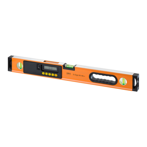
geo-FENNEL S-Digit 60 User manual

geo-FENNEL

geo-FENNEL S-Digit 60 User manual

geo-FENNEL GeoDist 60-GREEN User manual

geo-FENNEL

geo-FENNEL GeoDist 60-GREEN User manual

geo-FENNEL FL-200A-N User manual

geo-FENNEL

geo-FENNEL FL-200A-N User manual

geo-FENNEL Geo5X-L360 HP User manual

geo-FENNEL

geo-FENNEL Geo5X-L360 HP User manual

geo-FENNEL GeoDist User manual

geo-FENNEL

geo-FENNEL GeoDist User manual

geo-FENNEL FL 210A User manual

geo-FENNEL

geo-FENNEL FL 210A User manual

geo-FENNEL FET 200 User manual

geo-FENNEL

geo-FENNEL FET 200 User manual

geo-FENNEL S-Digit mini User manual

geo-FENNEL

geo-FENNEL S-Digit mini User manual

geo-FENNEL FL 1000 HP User manual

geo-FENNEL

geo-FENNEL FL 1000 HP User manual

geo-FENNEL FL 270VA TRACKING User manual

geo-FENNEL

geo-FENNEL FL 270VA TRACKING User manual

geo-FENNEL FL 550H-G User manual

geo-FENNEL

geo-FENNEL FL 550H-G User manual

geo-FENNEL FL 275HV-TRACKING User manual
geo-FENNEL

geo-FENNEL FL 275HV-TRACKING User manual

geo-FENNEL FLG 250-Green User manual

geo-FENNEL

geo-FENNEL FLG 250-Green User manual

Popular Measuring Instrument manuals by other brands

Koso RS DYNO manual

Koso

Koso RS DYNO manual

Magnum Energy ME-BMK quick start guide

Magnum Energy

Magnum Energy ME-BMK quick start guide

Samson 024.85 Translation of the original operating instruction

Samson

Samson 024.85 Translation of the original operating instruction

Seametrics iMAG 4700 instructions

Seametrics

Seametrics iMAG 4700 instructions

PCB Piezotronics Triaxial ICP 639A91 Installation and operating manual

PCB Piezotronics

PCB Piezotronics Triaxial ICP 639A91 Installation and operating manual

Peak Atlas ESR60 user guide

Peak

Peak Atlas ESR60 user guide

Aquaread Aquaprobe AP-800 instruction manual

Aquaread

Aquaread Aquaprobe AP-800 instruction manual

LOVATO ELECTRIC DMED302 instruction manual

LOVATO ELECTRIC

LOVATO ELECTRIC DMED302 instruction manual

Bosch GAM 220 MF Operating/safety instructions

Bosch

Bosch GAM 220 MF Operating/safety instructions

HydroLogic BIGboy HL 19021 quick start guide

HydroLogic

HydroLogic BIGboy HL 19021 quick start guide

UEi DAFM3B instruction manual

UEi

UEi DAFM3B instruction manual

Simrad PI50 -  REV A datasheet

Simrad

Simrad PI50 - REV A datasheet

Urrea UMM01 Instructions and warranty

Urrea

Urrea UMM01 Instructions and warranty

MARTINDALE CM76 instruction manual

MARTINDALE

MARTINDALE CM76 instruction manual

Nautiques AirGuide 2025 Installation and operation guide

Nautiques

Nautiques AirGuide 2025 Installation and operation guide

RADWAG MA X2.A Series Startup guide

RADWAG

RADWAG MA X2.A Series Startup guide

ITRON DATTUS III Maintenance Overview

ITRON

ITRON DATTUS III Maintenance Overview

Hach 1720E user manual

Hach

Hach 1720E user manual

manuals.online logo
manuals.online logoBrands
  • About & Mission
  • Contact us
  • Privacy Policy
  • Terms and Conditions

Copyright 2025 Manuals.Online. All Rights Reserved.