Metrotech 810 DX Installation manual
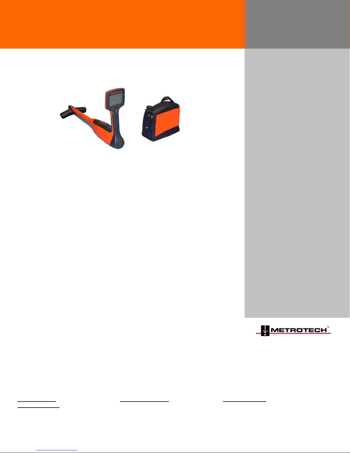
810 DX™ Pipe and Cable Locator
SERVICE CENTER, SALES AND TECHNICAL SUPPORT INFORMATION
Corporate Headquarters Metrotech Eastern U.S. Service Center Metrotech European Service Center
3251 Olcott Street 5211 Linbar Drive, Suite 50 Seba KMT
Santa Clara, CA 95054 Nashville, TN 37211 Dr. Herbert Iann St. 6
800-446-3392 800-624-6210 96148 Baunach, Germany
408-734-1400 Direct 615-366-7323 Direct +49 9544 680
408-734-1415 Fax 615-360-9855 Fax +49 9544 2273 Fax
www.metrotech.com [email protected] serv[email protected]
Warranty: One year. Specifications Subject to change without notice, ISO 9001:2000 Certified. Copyright 2008. All Rights Reserved. Rev 9/9/08
OPERATIONS MANUAL
810DX 9/9/2008 REV D 2
ISO 9001:2000 CERTIFIED
Metrotech has received ISO 9001:2001 Quality Management System Certification.
Metrotech adheres to the quality standard guidelines of ISO 9001:2001 and ensures quality in its
design/development, production, installation, and servicing disciplines.
© Metrotech Corporation 2008
Metrotech Corporation
3251 Olcott Street,
Santa Clara, CA 95054
Tel: 1.800.446.3392; 1.408.734.1400
Fax: 1.408.734.1415
E-mail: [email protected]
Internet: www.metrotech.com
Revision D, 9/9/08

810DX 9/9/2008 REV D 3
TABLE OF CONTENTS
List of Illustrations………………………………………….4
1 Introduction ………………………………………………6
2 Safety Precautions………………………………………6
3 810DX Quick Start Guide for the
Experienced User………………………………………..6
4 Model 810Dx Equipment………………………………..7
4.1 810Dx-D Standard Equipment…………………….7
4.2 810Dx-R Standard Equipment……………………..8
4.3 Accessories………………………………………….9
4.4 Technical Specifications…………………………..10
4.5 Transmitter: Controls
Indicators, and Features …………………………..11
4.6 Receiver: Control, Indicators, and
Features……………………………………………..14
5 Checkout Procedure…………………………………….17
6 Operation………………………………………………….18
6.1 Transmitter Set-up………………………………….18
6.2 Receiver Operation……………………..…………..21
7 Advanced Locating Techniques ………………………25
7.1 Ground Survey………………………………………25
7.2 Adjacent Utilities..…………………………………...26
7.3 Deep Utility…………………………………………..27
7.4 Tracing Long Runs………………………………….27
7.5 Locating a Service Lateral…………………………27
7.6 Locating a Bend or Dead End……………………..27
7.7 Valves, Manhole Cover, T’s and
Risers…………………………………………………27
7.8 Common Bonded Utilities………………………….28
7.9 Congested Areas……………………………………29
7.10 Determining If You Have a “Ghost”
Utility………………………………………………….30
7.11 Pipes with Insulated Junctions…………………….30
7.12 Distribution Systems………………………………..30
7.13 Non-Metallic Pipes………………………………….30
7.14 Tracer Wire………………………………………….30
8 Maintenance……………………………………………..30
8.1 Replacing the 810Dx D-Cell
Transmitter Batteries……………………………….31
8.2 Replacing the 810Dx NiMH Transmitter
Rechargeable Battery………………………………31
8.3 Recharging the 810Dx NiMH Transmitter
Rechargeable Battery………………………………31
8.4 Service Center Information………………………..34

810DX 9/9/2008 REV D 4
Appendix………………………………………………………35
Copyright Notice……………………………………………..35
Warranty……………………………………………………….36
List of Illustrations
Figure 4-1: Model 810Dx™ Pipe and Cable
Locator - Standard Equipment…………………….……..7
Figure 4-2: Model 810Dx™ Pipe and Cable
Locator with NiMH Transmitter Batteries……………….8
Figure 4-3: 810Dx Transmitter: Controls
and Indicators……………………………………………….12
Figure 4-4: 810Dx Transmitter: Utility
Line Resistance Chart……………………….…………….13
Figure 4-5: 810Dx Receiver: Controls
and Indicators……………………………………………….14
Figure 4-6: 810Dx Receiver LCD Display………………15
Figure 4-7: 810Dx Receiver LCD Display:
Depth Mode……………….…………………………………15
Figure 5-1: Connect Transmitter Leads..………………17
Figure 5-2: Aim Receiver at Transmitter………………18
Figure 6-1: Direct (Conductive) Connection….………19
Figure 6-2: Inductive Coupling with the
MetroClamp………………………………….…………….…20
Figure 6-3: Transmitter Position for
Inductive Tracing……………………………………………21
Figure 6-4: Receiver Position for Tracing……………..22
Figure 6-5: Receiver Position When
Determining Depth………………………………………….23
Figure 6-6: Principle of Triangulation…………………..23
Figure 6-7: Receiver Position for Triangulation………24
Figure 6-8: Locate Centerline………...………..………..24
Figure 6-9: Multiple Utilities in a
Common Trench……………………………..25
Figure 7-1: Blind Search Parallel Pattern………………26

810DX 9/9/2008 REV D 5
Figure 7-2: Adjacent Utilities - Position
of Ground Lead……………………………………………..27
Figure 7-3: Locating Service Laterals………………….28
Figure 7-4: Locating a Bend……………………………..28
Figure 7-5: Locating a Dead End………………………..28
Figure 7-6: Incorrect Coupling for
Congested Area…………………………………………….. 29
Figure 7-7: Correct Coupling for
Congested Area…………………………………………….. 29
Figure 8-1: Replacing the D-Cell
Transmitter Batteries……………………………………….31
Figure 8-2: Replacing the D-Cell
batteries with the NiMH battery pack…………………… 31
Figure 8-3: Recharging the NiMH
battery pack with the Wall Mount Charger…………….. 31
Figure 8-4: Recharging the NiMH
battery pack and operating from an external
12-volt DC supply……………………………………………32
Figure 8-5: Replacing the 810Dx
Receiver Batteries………………………………………….. 33
1 INTRODUCTION

810DX 9/9/2008 REV D 6
This manual describes the Metrotech Model 810Dx™ Pipe and Cable Locator. Included is an
equipment description, product specifications, checkout procedures, operating procedures,
application information and maintenance instructions.
The Model 810Dx is a state-of-the-art pipe and cable locator precisely designed with many
powerful features to provide you with optimum information about your locate situation.
2 SAFETY PRECAUTIONS
1 Metrotech pipe and cable locators are intended for use by utility and contractor
professionals. Safety hazards for underground utility access areas include electrical
shock, explosive gases, and toxic fumes as well as potential influence on
communications and control systems such as traffic control and railroad crossings.
2 Familiarize yourself with all required safety practices of the local utility company, or other
owner of the plant before entering an access area or connecting a Metrotech transmitter.
3 Before connecting the transmitter directly to any utility, make sure that the line is de-
energized and out of service. Never make a direct connection to a live power cable.
4 If you use the MetroClamp on energized electrical or control lines follow appropriate
safety procedures to avoid the risk of injury.
5 Pay special attention when using a locator in high traffic areas.
3 810Dx QUICK START GUIDE FOR THE EXPERIENCED USER
1 Check Batteries – Turn Transmitter ON. If the battery status is low (less than 25%)
replace or recharge the battery.
2 Connect Transmitter to Utility - Turn Transmitter “OFF”. Plug the Conductive
Attachment into Transmitter. Stretch black lead 90 degrees away from utility. Press
ground rod into the earth. Clamp black lead to grounding rod. Clamp red lead to target
utility. Turn Transmitter “ON”.
3Adjust Receiver Controls - Turn Receiver “ON”.
4 Sweep Area Around Transmitter – Circle Transmitter with Receiver at a distance of 10
feet (3 m). Left/Right display and Receiver signal strength will indicate location of buried
utilities.
5 Locate Line - Follow your target utility, sweeping left and right as you walk away from
the Transmitter. Mark the centerline on the ground.
6 Measure Depth - Hold the Receiver over the centerline and press the depth button. The
LCD will display the depth in feet and inches.
4 MODEL 810Dx™ EQUIPMENT

810DX 9/9/2008 REV D 7
4.1 810Dx-D Standard Equipment (Alkaline Transmitter Batteries)
Part # Description
10293 Receiver 83kHz
10294 Transmitter 83kHz
800B004 Conductive Attachment Direct Connect
Assembly Ground Rod
10826 Hard Carrying Case
10943 Operation Manual
Figure 4-1: Model 810Dx™ Pipe and Cable Locator - Standard Equipment
1. 810Dx Receiver
2. 810Dx Transmitter
3. Conductive Attachment
4. Ground Rod
5. Operation manual
6. Carrying Case
4.2 810Dx-R Standard Equipment (NiMH Transmitter Batteries)

810DX 9/9/2008 REV D 8
Part # Description
10293 Receiver 83kHz
10874 Transmitter 83kHz w/ NiMH Batteries
10793 Wall Mount Charger
800B004 Conductive Attachment Direct Connect
Assembly Ground Rod
10826 Hard Carrying Case
10943 Operation Manual
Notice: Please contact factory for wall mount chargers versions outside of USA and Canada.
Figure 4-2: Model 810Dx™ Pipe and Cable Locator with NiMH Transmitter Batteries
1. 810Dx Receiver
2. 810Dx Transmitter
3. Conductive Attachment
4. Ground Rod
5. Operation Manual
6. Carrying Case
7. Wall Mount Charger
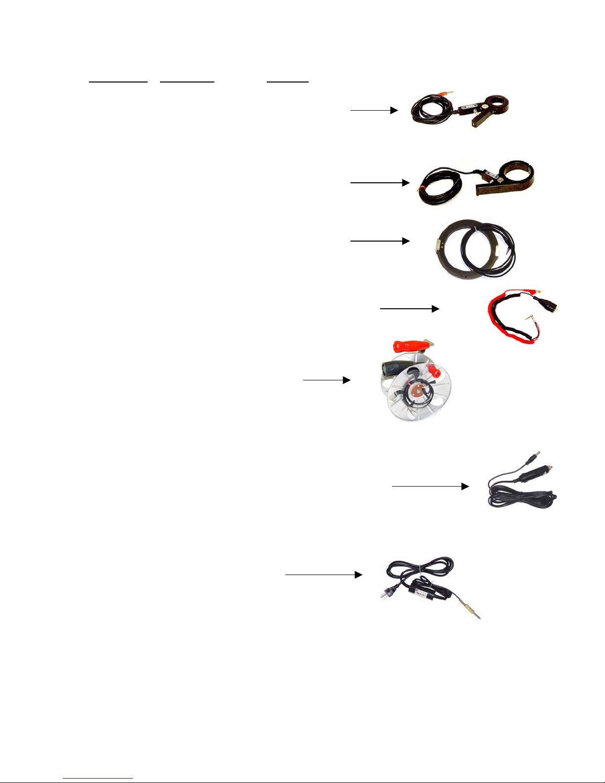
4.3 Accessories
810DX 9/9/2008 REV D 9
Part/Model # Description Remarks
4290 2” MetroClamp For Inductive
Coupling
4490 4” MetroClamp For Inductive
Coupling
4890 8” MetroClamp For Inductive
Coupling
400B246 Conductive Attachment Telephone style Clips
400A132 100’ Ground Lead Extension
10873 12-volt DC power lead For use with external power source e.g.
Vehicle cigarette lighter and transmitter
battery recharging.
10126 Live Power Connector
4.4 Technical Specifications

810DX 9/9/2008 REV D 10
TRANSMITTER
Output Frequencies: 83.0775kHz
Output indicator: Low/Medium/High LED
Output Power: 1 Watt
Power Settings: Low, Medium, High
Modes: Direct connection, Clamp and Inductive
Voltage protection: 250VAC
Battery Type: Six D Cells
Optional NiMH
Battery Life: Alkaline 100 hours Continuous use
NiMH 50 hours Continuous use,
depending on power selection.
External power source: 12VDC auto line input
Battery Check: Continuous
Operating temperature: -4º to +122º F (-20º to +50º C)
Environmental resistance: IP54
Dimensions: 8.5” L x 4.63” W x 7.0” H
(21.6 x 11.8 x 17.8 cm)
Weight: w/D Cell (5.16 lbs. - 2.34 kg)
w/NiMH (5.48 lbs. - 2.48 kg)
RECEIVER

810DX 9/9/2008 REV D 11
Receiving frequency: 83.0775kHz
Depth Accuracy: 0-10’ +/-(5% + 2”) under normal conditions
10’-20’ +/-(10% +2”) under normal conditions
Features: Distance Sensitive Left/Right GuidanceTM
Real-Time Continuous Gain AdjustmentTM
Push Button Depth
Backlightingstandard
Serial link RS232
Battery Type: Eight AA Alkaline Cells
Battery Life: 85 hours continuous use
75 hours continuous backlit use
Battery Check: Continuous Automatic Operation
Temperature: -4º to +122º F (-20º to +50º C)
Environmental resistance: IP54
Dimensions: 28.7” L x 8.63” W x 12.25” H
(72.9 x 21.9 x 31.1 cm)
Weight: (4.14 lbs.- 1.88 kg.)
4.5 Transmitter: Controls, Indicators, and Features
4.5.1 Transmitter Controls and Indicators - See Figure 4-2 for the location of the controls and
indicators described below:
Output Jack - Insert the Direct Connect cable or the MetroClamp cable into this jack. (Located
under the connection cover of the Transmitter).
Inductive Position – Place the transmitter over your targeted utility as shown on the label of the
transmitter.
External Power/Charger Jack- The transmitter can be powered by external 12VDC supply e.g.
from vehicle battery by connection to the external/charger jack. Connection of the external
supply switches off internal batteries. The same jack connects the wall mount charger to charge
rechargeable batteries. If standard alkaline batteries are used no charging takes place.
Battery Door – The battery door is removed by rotating the ring latch. Slide the lid of the battery
door to gain access to the batteries. Observe battery polarity, which is indicated on the label
inside the battery compartment.

810DX 9/9/2008 REV D 12
810Dx TRANSMITTER
1 External Power/Charger Jack
2 Output Jack
3 Battery Door
4 ON/Off button
5 Power Level Output Button
6 Battery Charge State Indicator
7 Power level Indicator
`
Figure 4-3: 810Dx Transmitter: Controls and Indicators
:
Indicator LED Displays Three Types of Information
1) Battery Status – Battery charge state indicated by flashing LED at indicated level
100/50/25%.
2) Power Level Setting – The flashing LED indicates the transmitter output power level setting
(Low/Medium/High).
3) Transmitter output Check – The 810Dx transmitter has a feature that will check the output of
the transmitter taking into account the entire locate circuit including the resistance offered by
the utility, the ground, the connection point and the Power level selected. The indicated
Output Level is used to determine the potential quality of the locate. Most importantly the
Output Level check will indicate if the Output is too low for good locate. Low Output Level is
an indication of high resistance in the circuit reducing the Output Level. Low Output Level
means low signal strength and the receiver may not determine centerline or depth with any
accuracy. Always improve the ground and or utility connection to increase the Output Level.
To check the transmitter Output Level, press and hold the Power Level Output Button. An
LED will indicate the output level at the Power Level selected. Refer to the Output Level and
Locate Quality Chart Figure 4-4. Improve the ground and or direct connection if a Low or no
Output Level is indicated.
2
4
7
6
1
3
5

810DX 9/9/2008 REV D 13
Power level Selector – Change level by pressing power output level selector. Press once to
decrease from HIGH to MEDIUM, MEDIUM LED now flashing. Press again to decrease from
MEDIUM to LOW, LOW LED now flashing. Press again to return to HIGH power
Power Setting HIGH 1.0 Watts
MEDIUM 0.5 Watts
LOW 0.2 Watts
Figure 4-4: 810Dx Output level and locate quality chart
4.5.2 Transmitter Features
Automatic Impedance Matching - Automatically matches the Transmitter to the line impedance
to provide maximum output in direct mode.
Output Level Indicator - Provides information on the locate quality in the three power level
modes. Please see Fig. 4-4
Standard Alkaline D cells or Rechargeable Batteries – Battery compartment can
accommodate standard D cell alkaline batteries or Metrotech supplied NiMH battery pack.
Smart charging circuit™ automatically detects presence of Alkaline or NiMH battery pack.
Battery level Indicator – Indicates battery charge status.
Inductive Antenna - Provides locating capability where direct connect or Metroclamp utility
access is not available.
Multiple Power Levels - Provides maximum flexibility for all locating jobs from high congestion to
long distance tracing.
Utility Line Locate Quality Check
Output Power Selection Indicated Output Locate Quality
High Excellent
Medium Good
Low Poor
High
None Improve Connection
Medium Excellent
Low Good
Medium
None Improve Connection
Low Good
Low None Improve Connection
810DX 9/9/2008 REV D 14
810Dx RECEIVER
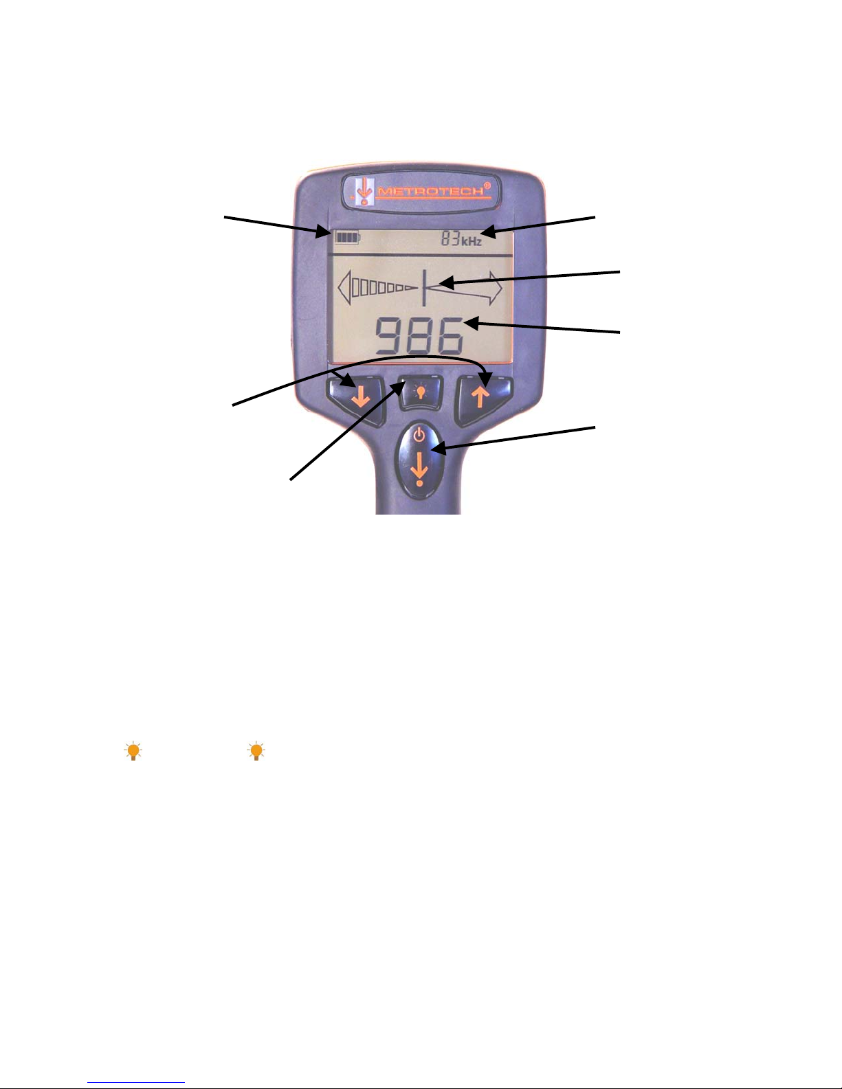
Figure 4-5: 810Dx Receiver - Controls and Indicators
4.6 Receiver: Controls and Indicators
4.6.1 Receiver Controls and Indicators
See Figure 4-5 for the location of the controls and indicators described below:
ON/OFF Depth button - Turn ON by a quick press of the ON/OFF DEPTH button. Turn OFF by
extended press (3 seconds) on ON/OFF DEPTH button. Take depth reading by quickly pressing
the ON/OFF DEPTH button.
Button – Press once to turn the backlight on. Press once to turn the backlight off.
Volume UP/DOWN buttons – Change speaker volume by pressing UP button or DOWN button.
Receiver emits tone at new volume level.
Battery Charge
Status Operating Frequency
Signal Strength
Distance Sensitive
Left/Ri
g
ht Guidance
Backlight
Volume up/down arrows On/Off Depth Button
810DX 9/9/2008 REV D 15
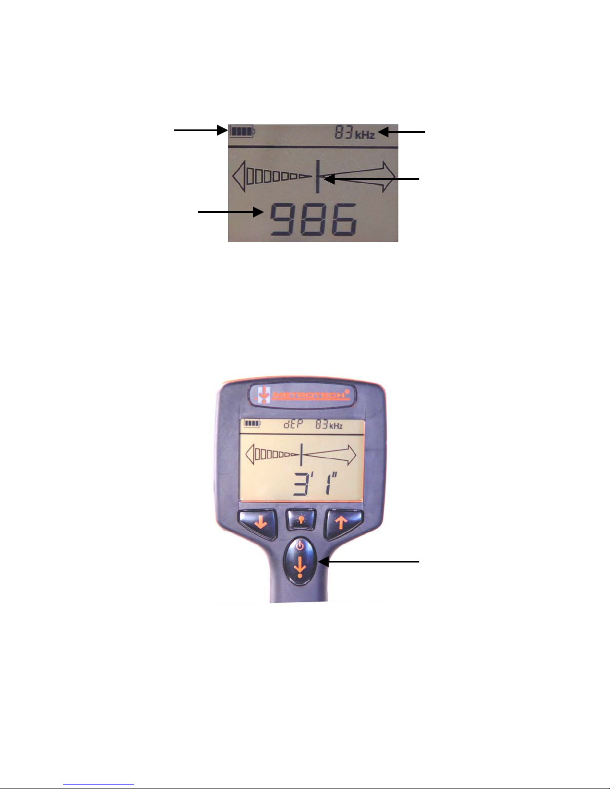
Receiver DISPLAY (Liquid Crystal Display) - Displays the battery status, operating frequency,
Distance Sensitive Left/Right Guidance™, and signal strength.
1 Battery Status
2 Operating Frequency
3 Distance Sensitive Left/Right Guidance
4 Signal Strength
Figure 4-6: 810Dx Receiver Display
The receiver displays depth estimation in feet and inches or centimeters.
Figure 4-7: 810Dx Receiver LCD Display: Depth Mode
1
2
3
4
Depth Button

810DX 9/9/2008 REV D 16
SPEAKER - Emits audio tone to guide operator toward the targeted utility.
BATTERY COMPARTMENT – To open, turn spring-loaded quarter-turn latch counter clockwise
to release battery compartment door. Separate battery compartment from receiver housing, slide
cover and gain access to the batteries. To open the battery compartment door, turn the spring-
loaded quarter and separate the compartment door by gently pulling on the latch.
N
AUTO/MAN
4.6.2 Receiver Features
Distance Sensitive Left/Right Guidance™ -Provides visual and audible direction and distance
information guiding you to the target utility.
Battery Charge Status - Continuously displays remaining battery charge status provides
flashing low power alert.
Depth Button - Provides quick depth estimation in feet and inches (or in cm).
Real-Time Continuous Gain Adjustment™ - Automatic gain continuously optimizes the
sensitivity of the Receiver eliminating the need for manual gain adjustment.
Simultaneous Peak and Null Display™ - Provides signal strength and centerline
simultaneously for fast productive locating.
Battery Saving Automatic Power Down - After five minutes of no activity, the Receiver turns off
to save battery life.
Depth Measurement to 20 Feet (6 m) - Depth measurement range is up to 20 feet (6 m).
RS232 Serial Communication Port - Provides data transfer capability for calibration and service.

810DX 9/9/2008 REV D 17
5 CHECKOUT PROCEDURE
For proper operation of the Model 810Dx Pipe and Cable Locator, use this checkout procedure:
• upon receiving the equipment
• before each job, preferably before you leave for the site
• if problems arise during a locate
1 Place transmitter on the ground. Plug conductive attachment leads into the
Transmitter, and attach them to one another. As shown in Figure: 5-1
2 Turn the Transmitter “ON”. Check the output power level setting is at high, indicated by a
flashing LED. Note battery charge status. If charge is low, replace or recharge
Transmitter batteries.
3 Perform output check by pressing the output power level button continuously. The
flashing LED will change to a constant LED at high, confirming Transmitter and
Conductive Attachment is in good working condition.
4 Turn the Receiver “ON”. Slowly swing the Receiver side to side while pointing it at the
transmitter. The Distance Sensitive Left/Right GuidanceTM System display should
respond. The signal strength should also respond to the movement and be at its
highest
when pointed directly at the transmitter. See Figure 5-2.
Figure 5-1: Connect Transmitter Leads

810DX 9/9/2008 REV D 18
Figure 5-2: Aim Receiver at Transmitter
6 OPERATION
Follow the Checkout Procedure described in Section 5 before operating the equipment. To
operate the 810Dx Utility Line Locator use the Transmitter to apply the signal to the utility, and
use the Receiver to trace the signal from the utility.
WARNING
Never make a direct connection to a live power cable. Always test the cable first and make
sure the power cable has been taken out of service, is fully discharged and grounded before you
make a direct connection to it. If you use the MetroClamp on energized electrical or control lines,
follow appropriate safety procedures to avoid the risk of injury.
6.1 Transmitter Set-up
6.1.1 Check the Battery - Turn the Transmitter “ON” by pressing the ON/OFF button. Battery
status will be indicated by the flashing LEDs at the following charge states.
100% charge
50% charge
25% charge
0% charge – no lights flashing

810DX 9/9/2008 REV D 19
6.1.2 Methods of Applying Signal to a Utility - The three methods of applying the signal to the
utility are - Direct Connect, Inductive Coupling, and Inductive. Following is a description of each
method and instruction of use.
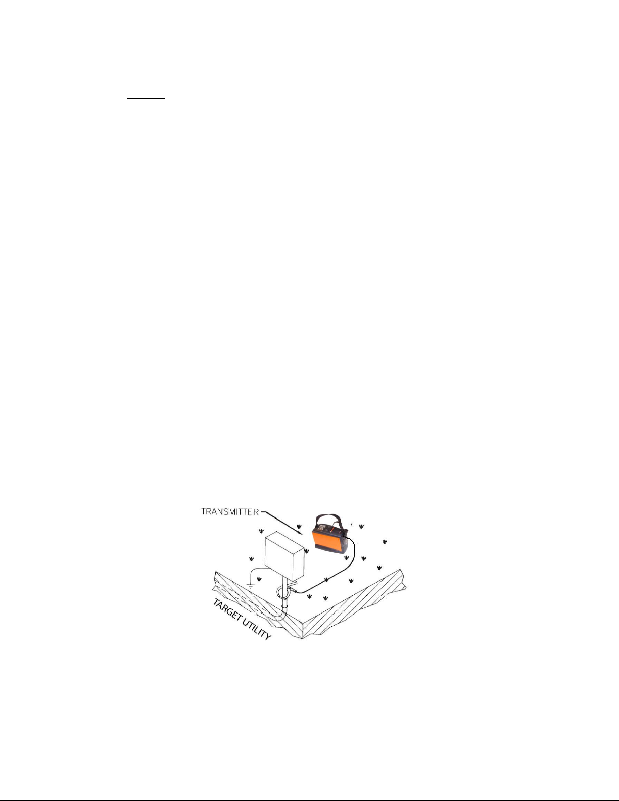
ADirect (Conductive) Connection - This is the preferred mode of operation because the
transmitter is connected directly to a metallic part of the utility (hydrant, meter, riser, valves,
sheath, and tracer wire), allowing maximum signal to reach the utility. In this operating mode the
Receiver can be closer to the Transmitter, and adjacent buried utility interference is reduced.
1 Insert the Conductive Attachment - Turn the Transmitter off. Insert the Direct Connect
Cable into the OUTPUT JACK on the Transmitter.
2 Set up and connect to a ground - Extend the BLACK lead of the Direct Connect Cable
at a right angle as far as possible from the utility. Press the ground spike into the ground
as far as possible, then attach the black clip. If the ground spike cannot be used,
connect to appropriate ground using an extension reel. Look for a convenient existing
ground, such as a metal street sign. Be careful not to get close to or cross any adjacent
buried utility. If no existing ground is available, use the ground spike. Drive the ground
spike as far into the ground as possible, and attach the BLACK lead. See Figure 6-1.
3 Connect to your utility - Connect the RED lead of the Direct Connect Cable to the
targeted utility. Make sure of good metal to metal contact.
Figure 6-1: Direct (Conductive) Connection
4 Turn Transmitter ON – Press ON/OFF button to turn Transmitter ON. Transmitter comes
on in High power mode.
5 Select Transmitter output power – The 810DxTransmitter has three output power
settings – HIGH, MEDIUM, and LOW
810DX 9/9/2008 REV D 20
Transmitter Output
Setting
High 1.0 Watts
Medium 0.5 Watts
Low 0.2 Watts
Decrease output power by pressing the OUTPUT button. Press once to decrease from
HIGH to MEDIUM, MEDIUM LED now flashing. Press again to decrease from MEDIUM
to LOW power. Press again to return to HIGH power.
6 Transmitter Output Check – Pressing power output level button continuously checks the
locate quality of the targeted utility. A constant LED represents output current is applied
to the targeted utility. If the high power level is selected and the LED is on high, it means
maximum output current is on the targeted utility line. If no LED is indicated, regardless of
the power level selected, improve connection. Improving your ground connection and/or
the quality of the direct connection, can reduce the amount of resistance in the circuit and
improve the output current on the target utility. Wetting the area around the ground rod
will increase the output current.
BInductive Coupling with the MetroClamp - If direct connection is not possible, Inductive
Coupling is the next best method of applying signal onto the target utility. MetroClamps are
available in three sizes, 2 inch (4290), 4 inch (4490), and 8 inch (4890). Place an inductive
MetroClamp around the utility.
MetroClamp Ground Requirements – When using a MetroClamp around a cable, both ends of
the cable must be grounded. This ensures a ground return path for optimum current flow (signal
strength). Power lines and telephone sheaths are generally grounded. When tracing lines that
have insulators (i.e. gas meters), the insulators should be temporarily bypassed, using a jumper
cable.
1 Connecting the MetroClamp - Turn the Transmitter “OFF”. Plug the MetroClamp cable
into the OUTPUT JACK on the 810Dx Transmitter.
2Positioning the MetroClamp - Place the MetroClamp around the utility, below the
electrical ground. Make sure the clamp jaws are completely closed. See Figure 6-2.
Figure 6-2: Inductive Coupling with the MetroClamp
4 Turn the Transmitter ON
5 Trace your utility - Refer to Section 6.2 for tracing instructions.
C Inductive (Indirect Method) - This is the least effective method of applying signal to isolate
Table of contents
Other Metrotech Measuring Instrument manuals


Popular Measuring Instrument manuals by other brands

Aqualytic
Aqualytic CHECKIT Comparator instruction manual

MH Corbin
MH Corbin NC350 Operation manual addendum

Powerline
Powerline A3 instruction manual

Ono Sokki
Ono Sokki SE-1200 instruction manual

Delta OHM
Delta OHM HD52.3D... series operating manual

Challenger Optics
Challenger Optics CO-OLS-MPO12 Interactive operating manual


