Digga Mini Bigfoot Trencher User manual

1
MINI BIGFOOT TRENCHER
OPERATORS MANUAL
PM-000042-C

2PM-000042-C Mini Bigfoot Trencher Operators Manual - June 2021

3
Your Digga Mini Bigfoot Trencher is a high performance attachment, tted with a Digga planetary gearbox, that
is designed for trenching. To avoid premature wear and failure, and to full your terms of warranty please read
this statement.
Your Digga Mini Bigfoot Trencher gearbox must have a rst oil change within the rst 30 hours (extreme
use) or 50 hours (moderate use) or 3 months (whichever comes rst) of use to ensure the bed in of the
gearbox. For more detailed information please read page 28.
If the rst oil change is not performed within this period, excessive wear within the gearbox can occur
that will cause premature failure. All warranty will be voided.
Oil must then be changed thereafter every 300/500 hours and a full service every 12 months must be
performed by an authorised service agent to ensure Warranty requirements are met.
In the event of a failure under the warranty period:
• Contact Digga immediately, DO-NOT DISASSEMBLE YOUR TRENCHER without rst obtaining written
permission and instructions from Digga.
• Proof of service must be provided in hard copy form of both operational and service history (including
serial number of gearbox and hydraulic motor) records. Service must be performed by an authorised
Digga service agent.
CRITICAL - DO NOT CONNECT OR OPERATE YOUR TRENCHER
WITHOUT FIRST HAVING READ AND UNDERSTOOD THIS STATEMENT
1 CRITICAL INFORMATION - SERVICE INTERVALS

4PM-000042-C Mini Bigfoot Trencher Operators Manual - June 2021
2 TABLE OF CONTENTS
1 CRITICAL INFORMATION - SERVICE INTERVALS............................... 3
2 TABLE OF CONTENTS.......................................................................... 4
3 TO THE PURCHASER........................................................................... 5
4 SERVICE & PREPARATION FOR USE.................................................. 6
5 SAFETY PRECAUTIONS - GENERAL INFORMATION.......................... 8
6 SAFETY - WORKING WITH THE ATTACHMENT................................... 14
7 BEFORE USE........................................................................................ 16
8 INSTALLATION AND OPERATING INSTRUCTIONS............................. 17
9 MAINTENANCE..................................................................................... 24
10 SAFETY - STICKER LOCATION............................................................. 29
11 SPARE PARTS....................................................................................... 31
12 TROUBLESHOOTING........................................................................... 33
13 WARRANTY STATEMENT...................................................................... 35

5
3 TO THE PURCHASER
ABOUT THIS MANUAL
This manual has been designed to help you do a better,
safer job. Read this manual carefully and
become familiar with its contents.
Remember; never let anyone operate this unit without
reading the “Safety Precautions” and “Operating
Instructions” sections of this manual.
Unless noted otherwise, right and left sides are
determined from the position of the operator when
behind the product facing forward.
SAFETY ALERT SYMBOL
This is the “Safety Alert Symbol” used by this industry. This symbol is used to warn
of possible injury. Be sure to read all warnings carefully. They are included for your
safety and for the safety of others working with you.
THANK YOU
Congratulations on the purchase of your new Digga Trencher!
Contact your Digga dealer for any further information pertaining to this product or for further information on other
products available in the Digga range.

6PM-000042-C Mini Bigfoot Trencher Operators Manual - June 2021
4 SERVICE & PREPARATION FOR USE
The parts department needs this
information to insure accurate
parts can be sent to the
authorised service agent.
MODEL
SERIAL NUMBER
DATE PURCHASED
MODELS COVERED IN THIS MANUAL
Mini Bigfoot Trencher
All Digga Trenchers are designed and manufactured to give dependable service. To keep it running eciently read the instructions in
this operator’s manual. Each section is clearly identied so that you can easily nd the information you need - whether it is operation,
lubrication or maintenance.
Trencher equipment options are available to help you do a better job in special conditions. These are noted throughout this manual and
can be purchased from your Digga dealer e.g. chains, wear parts, crumber bar, spare parts, and dierent width chains.
To facilitate warranty or service, record the model and serial number of your unit in the space provided on this page must be provided.
This information may be obtained from the identication plate located on the product.
ALL SERVICE FOR WARRANTY MUST BE PERFORMED BY AN AUTHORISED DIGGA SERVICE AGENT. CONTACT YOUR
LOCAL DIGGA DEALER FOR DETAILS.
IMPORTANT: EXCEPT FOR OIL CHANGES, GENERAL MAINTENANCE OF
CHAINS AND BEARINGS, ALL SERVICE AND REPAIR FOR WARRANTY
AND ASSESSMENT FOR WARRANTY MUST BE PERFORMED BY
AN AUTHORISED DIGGA SERVICE AGENT, ONLY GENUINE DIGGA
REPLACEMENT PARTS CAN BE USED. SUBSTITUTE PARTS WILL
NOT MEET THE STANDARDS REQUIRED FOR SAFE, DEPENDABLE
OPERATION. USE OF NON GENUINE DIGGA PARTS WILL VOID
WARRANTY AND DIGGA WILL ACCEPT NO LIABILITY WHAT SO EVER
FOR CONSEQUENTIAL OR SPECIAL DAMAGES.
7
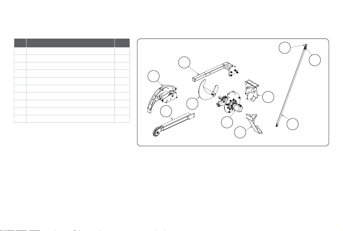
To avoid any inconvenience before operation, please check that you have received the following items which you may have ordered:
4 SERVICE & PREPARATION FOR USE
The Digga Trencher receives its power from the parent machine through the Auxiliary Valve circuit with Quick Release Couplers normally
located on the machine arms near the front. Attaching points on the Trencher are the same as the bucket attaching points on your machine.
Assemble the Trencher if required. Hook up hoses to auxiliary hydraulics.
Engine must be shut o. Check that the chain rotation on the Trencher is anti-clockwise when viewed from the Motor side of the Trencher.
NB: Two way ow is required for anti-clockwise rotation.To assure optimum motor life, run Hydraulic motor for one hour on
approx. 1/3 RPM before application of full load. Ensure your machines ow and pressures do not exceed the maximum rated ow and
pressures of the Trencher (Refer page 5 To the Purchaser)
IF YOU ARE IN ANY DOUBT CONTACT YOUR NEAREST DIGGA DEALER FOR ASSISTANCE.
REF DESCRIPTION QTY
A GEAR BOX AND MOTOR ASSEMBLY 1
BSPOIL AUGER 1
CHITCH PLATE-SLIDING SIDE SHIFT 1
DCRUMBER BAR 1
E DANGER BAR 1
F OUTER BOOM 1
G ADJUSTABLE SKID FOOT 1
H HYDRAULIC HOSES 2
I MALE COUPLER 1
J FEMALE COUPLER 1
D
E
F
B
A
G
C
H
I
J
8PM-000042-C Mini Bigfoot Trencher Operators Manual - June 2021
SIGNAL WORDS: Note the use of signal words DANGER, WARNING, and CAUTION with the safety messages. The appropriate signal word for
each has been selected using the following guidelines:
DANGER: Indicates an imminently hazardous situation, which if not avoided, will result in death or serious injury. This signal word is to be limited
to the most extreme situations, typically for machine components which, for functional purposes, cannot be guarded.
WARNING: Indicates a potentially hazardous situation, which if not avoided, could result in death or serious injury, and includes hazards that are
exposed when guards are removed. It may also be used to alert against unsafe practices and indicate potential failure or damage to equipment.
CAUTION: Indicates a potentially hazardous situation, which if not avoided, may result in minor or moderate injury. It may also be used to alert
against unsafe practices.
TAKE NOTE! THIS SAFETY ALERT SYMBOL FOUND THROUGHOUT THIS MANUAL IS USED TO CALL YOUR ATTENTION TO
INSTRUCTIONS INVOLVING YOUR PERSONAL SAFETY OR OTHERS. FAILURE TO FOLLOW THESE INSTRUCTIONS CAN RESULT IN
INJURY OR DEATH.
ATTENTION!
BECOME ALERT!
YOUR SAFETY IS INVOLVED!
THIS SYMBOL MEANS:
This section is composed of various warnings and safety tips. Read and learn all the information in this section before you attempt to use
your attachment. Also read your machines owner’s manual before using your equipment. This knowledge will help you operate your unit safely.
Do not take this information lightly, it is presented for your benet and for the benet of others working around you.
The “Safety Alert Symbol” will be used throughout this manual. It will appear with the word DANGER, WARNING, or CAUTION, and a safety
message pertaining to the specic topic being covered. Take the time to read these messages as you come across them.
5 SAFETY PRECAUTIONS - GENERAL INFORMATION

9
KNOW WHERE UTILITIES ARE
Observe overhead electrical and other utility lines. Be sure equipment will clear them. When digging, call DIAL BEFORE
YOU DIG ON 1100 (in Australia), or your local utilities location service provider for location of buried utility lines, gas, water,
and sewer, as well as any other hazard you may encounter.
EXPOSURE TO RESPIRABLE CRYSTALLINE SILICA DUST ALONG WITH OTHER HAZARDOUS DUSTS MAY CAUSE
SERIOUS OR FATAL RESPIRATORY DISEASE.
It is recommended to use dust suppression, dust collection and if necessary personal protective equipment during the
operation of any attachment that may cause high levels of dust.
REMOVE PAINT BEFORE WELDING OR HEATING
Hazardous fumes/dust can be generated when paint is heated by welding, soldering or using a torch. Do all work outside or
in a well ventilated area and dispose of paint and solvent properly. Remove paint before welding or heating. When sanding
or grinding paint, avoid breathing the dust. Wear an approved respirator. If you use solvent or paint stripper, remove stripper
with soap and water before welding. Remove solvent or paint stripper containers and other ammable material from area.
Allow fumes to disperse at least 15 minutes before welding or heating.
END OF LIFE DISPOSAL
At the completion of the useful life of the unit, drain all uids and dismantle by separating the dierent materials (rubber,
steel, plastic, etc.). Follow all federal, state and local regulations for recycling and disposal of the uid and components.
WARNING
WARNING
WARNING
WARNING
5 SAFETY PRECAUTIONS - GENERAL INFORMATION

10 PM-000042-C Mini Bigfoot Trencher Operators Manual - June 2021
WARNING
WARNING
WARNING
OPERATING THE TRENCHER
• An operator must not use drugs or alcohol, which can change his or her alertness or coordination. An operator taking
prescription or over-the-counter drugs should seek medical advice on whether or not he or she can safely operate equipment.
• All bystanders should be kept a minimum of 20 feet (6 meters) away from the working area of the drive.
• Do not allow Site workers to climb or ride on Trencher at any time, including while stationary, in operation or being moved.
• Operate only from the operator’s station.
• Avoid steep hillside operation which could cause the machine to overturn. Consult your machines operator’s and safety
manuals for maximum incline allowable.
• Reduce speed when driving over rough terrain, on a slope, or turning, to avoid overturning the vehicle.
• Travel only with the trencher in a safe transport position to prevent uncontrolled movement. Drive slowly over rough ground
and on slopes.
• Do not drive close to ditches, excavations, etc., cave in could result.
• Before exiting the machine, lower the attachment to the ground, apply the parking brakes, turn o the prime mover’s
engine, and remove the key.
• Flow and pressure gauges, ttings, and hoses must have a continuous operating pressure rating of at least 25% higher than
highest pressures of the system.
• Do not smoke when refueling the prime mover. Allow room in the fuel tank for expansion. Wipe up any spilled fuel. Secure cap
tightly when done.
• Remove the trencher from the prime mover before transporting to and from the job site.
• Trenchers shall be used only for their designed intent and shall not be loaded beyond their rated capacity. Overloading or
exceeding the manufacturers specications will void all warranty.
5 SAFETY PRECAUTIONS - GENERAL INFORMATION

11
OPERATING THE TRENCHER (CONTINUED)
• The trencher must be stopped before making adjustments to the attachment.
• Spoil augers shall be cleaned only when the rotating mechanism is in neutral and the spoil auger stopped; a
long-handled shovel shall be used to move cuttings from the auger. Materials heavier than 10kgs must be moved
mechanically or by using at least two people.
• Trenching operations must be stopped in the event of local thunderstorm, or lightning activity. During operation,
weather conditions shall be monitored: operations shall cease during electrical storms or when electrical storms
are imminent.
• A trench that is left for prolonged periods of time must be capped and agged so it is clearly identied on
the work site.
STORAGE OF THE TRENCHER
• Seal hydraulic couplers from contaminants and secure all hydraulic hoses o the ground to help prevent damage.
• Clean the unit thoroughly, removing all mud, dirt, and grease.
• Inspect for visible signs of wear, breakage, or damage. Order any parts required and make the necessary repairs to
avoid delays upon removal from storage.
• Check that trencher motor and hoses are full of clean oil and planetary is full.
• Coat liberally with grease the output shaft and collar, extension shaft and collar, and all connecting pins to prevent
• rust and reduce wear.
• Tighten loose nuts, cap screws and hydraulic connections.
• Replace decals that are damaged or in unreadable condition.
• Store unit in a dry and protected place. Leaving the unit outside will materially shorten its life.
WARNING
WARNING
5 SAFETY PRECAUTIONS - GENERAL INFORMATION

12 PM-000042-C Mini Bigfoot Trencher Operators Manual - June 2021
5 SAFETY PRECAUTIONS - GENERAL INFORMATION
MAINTAINING THE TRENCHER
• Before performing maintenance, lower the attachment to the ground, apply the parking brakes, turn o the engine, and
remove the key.
• Never adjust a relief valve for pressure higher than recommended by the machine’s manufacturer.
WARNING
WARNING
TRANSPORTING
Follow all local government regulations that may apply along with recommended tie down points and any equipment safety
precautions at the front of this handbook when transporting your attachment.
TIE DOWN POINTS
• Tie down points are identied by tie down decals where required. Securing to trailer at other points is unsafe
and can damage attachment.
• Do not attach tie down accessories around cylinders or in any way that may damage hoses or hydraulic components.
• Attach tie down accessories to attachment as recommended.
• Check attachment stability before transporting.
Verify that all tie down accessories (chains, slings, ropes, shackles and etc.) are capable of maintaining attachment stability
during transporting and are attached in such a way to prevent unintended disengagement or shifting of the unit. Failure to do so
could result in serious personal injury or death.
GROUND PERSONNEL AND BYSTANDERS
• Be alert to others in the work area. Be sure others know when and where you will be working. Make sure no one is behind
equipment or within 6 metres of it operating.
• Loose tting clothing, long hair, jewellery and equipment which might become entangled in moving equipment are prohibited
while working near the Trencher.
• Operators, helpers, and other personnel working near Trencher must wear steel-toe safety shoes, safety glasses, and hard
hats as a minimum. Hearing protection, respirators, and personnel protective clothing will be specied in the site-specic
Health and Safety Plan.
WARNING
WARNING

13
TO THE OPERATOR
The primary responsibility for safety with this equipment falls to the operator. Make sure that the equipment is operated only by trained
individuals that have read and understand this manual. Don’t hurry the learning process or take the unit for granted.
It is the skill, care, common sense, and good judgement of the operator that will determine how eciently and safely the job is performed.
Know your equipment before you start. Know its capabilities and how to operate all the controls.
Visually inspect your equipment before you start, ensure correct assembly and installation of the attachment and never operate equipment
that is not in proper working order.
Practice the operation of your new attachment and become familiar with the controls and the way it handles on your machine. If there is any
portion of this manual or function you do not understand, contact your local authorized dealer or the manufacturer.
1. Never operate the Attachment without rst reading and understanding the entire operator’s manual.
2. Do not paint over, remove or deface any safety signs or warning decals on your equipment.
3. Follow all safety decals. Keep them clean and replace them if they become worn, damaged or illegible.
4. Know your equipment inside and out. Know how to operate all controls and know emergency shut down procedures.
5. Keep all stepping surfaces, pedals, and controls free from dirt, grease and oil. Keep equipment clean to help avoid injury from slipping
or a fall when getting on or o equipment.
6. Operate the attachment only in daylight or with sucient articial light.
7. Always carry loads close to the ground. Do not step o machine platform with load raised.
8. Turn o engine before performing maintenance. All maintenance can be performed with the machine arms lowered. If lift arms must
be left raised for any reason, use a positive lift arm lock to secure the arms in place. Serious damage or personal injury could result
from lift arms accidentally lowering.
9. Do not exceed rated operating capacity of the host machine, as machine may become unstable resulting in loss of control.
10. Always lower the loader arms or machine boom to the ground, shut o the engine and remove the key before getting o the unit.
11. Never use the Trencher on a machine that is not equipped with a cab or ROPS, and operator restraints
(seat belts or equivalent devices).
5 SAFETY PRECAUTIONS - GENERAL INFORMATION

14 PM-000042-C Mini Bigfoot Trencher Operators Manual - June 2021
6 SAFETY - WORKING WITH THE ATTACHMENT
WHEN DEALING WITH HYDRAULICS DURING ANY TYPE OF ASSEMBLY,
OPERATION, MAINTENANCE, OR OTHER WORK ON OR NEAR THIS PRODUCT
● Hydraulic uid under pressure can penetrate the skin and cause serious injury or death. Hydraulic leaks under pressure
may not be visible!
● If any uid penetrates the skin, GET IMMEDIATE MEDICAL ATTENTION!!
● Wear safety glasses, protective clothing, and use a sound piece of cardboard or wood when searching for hydraulic leaks.
DO NOT USE YOUR HANDS!
● Before connecting or disconnecting hydraulic hoses, read your machine or power unit’s operator’s manual for detailed
instructions on connecting and disconnecting hydraulic attachments.
● Make certain that all parts meet the specications for this product when installing or replacing hydraulic hoses or ttings.
● After connecting hydraulic lines:
○ Slowly and carefully raise the loaders arm/s and cycle the rollback / dump cylinders to check hose clearances and to
check for any interference.
○ Operate the hydraulics on this product to ascertain forward and reverse.
○ Make certain that the hoses cannot interfere with or actuate the quick-attach mechanism.
○ Make certain that hoses will not be pinched, or get tangled, in any equipment.
● Do not lock the auxiliary hydraulics of your power unit in the “ON” position.
● Refer to Machines operator manual and this manual for procedures and intervals, then inspect and maintain the entire
hydraulic system to insure that the uid remains clean, that all devices function properly, and that there are no
uid leaks.

15
WHEN MOUNTING THIS PRODUCT TO YOUR MACHINE
● Refer to the operator’s manuals of your machine, and your quick-attach for special or detailed mounting instructions.
● This product should t onto the quick-attach Frame or Hitch (Machine Mount).
● If this product does not t properly, contact your Digga Dealer before operating.
● Never place any part of your body into the mounting plate, frame, hitch or loader holes. A slight movement of the power unit
and this product could cause serious injury.
● Where ‘Dead Man’ connections are connected or installed it is illegal to disengage, tamper with or remove them.
For additional safety information please see Risk Management booklet. To obtain a copy contact Digga Head Oce on +61 7 3807 3330
WHEN ADJUSTING, SERVICING OR REPAIRING THIS PRODUCT
● Make no modications to your Trencher.
● When making repairs use only authorised Digga service agents, and genuine Digga parts. For fasteners, hydraulic hoses,
or hydraulic ttings, use only properly rated parts.
● Replacement parts must also have safety signs attached.
6 SAFETY - WORKING WITH THE ATTACHMENT
16 PM-000042-C Mini Bigfoot Trencher Operators Manual - June 2021
7 BEFORE USE
• Make sure that all nuts and bolts are in place and properly tightened.
• Make sure that all other fasteners are in place and are performing their specied function.
• Make sure that all hydraulic ttings are tightened and that there are no leaks in any ttings or hoses.
• Make sure that all safety signs are in place, are clean, and are legible (see the safety sign section).
• Check for any oil leaks.
• Wear and tear on pins, linkages, clips, bushes and hood.
• Ensure any damage or excessively worn parts are replaced.
• Always wear safety goggles or glasses when inspecting equipment.
SAFETY FIRST!! READ AND UNDERSTAND THE SAFETY INSTRUCTIONS
BEFORE BEGINNING ANY TRENCHER MAINTENANCE.
BEFORE FIRST USE
BEFORE EACH USE
● Inspect the attachment for shipping damage. If damage does exist, do not operate until the damaged parts have
been replaced or repaired.
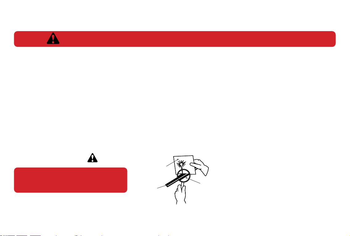
Escaping uid under pressure can have
sucient force to penetrate the skin
causing serious personal injury. Fluid
escaping from a very small hole can
be almost invisible. Use a piece of
cardboard or wood, rather than hands
to search for suspected leaks. Keep
unprotected body parts, such as
face, eyes, and arms as far away as
possible from a suspected leak. Flesh
injected with hydraulic uid may develop
gangrene or other permanent disabilities.
If injured by injected fluid, see a doctor at
once. If your doctor is not familiar with this
type of injury, ask him to research it
immediately to determine proper treatment.
WARNING!
CARDBOARD
HYDRAULIC HOSE
OR FITTING
MAGNIFYING GLASS

17
The following instructions will help you to mount your Trencher onto your machine. The Trencher uses the quick-attach system for ease of
installation. Therefore, if you know how to attach your loader bucket, attaching the Trencher should prove no problem. Remember to read
all safety warnings, decals and operating instructions before operating the Trencher.
If there is any portion of this manual that you do not understand, contact your Digga dealer.
8 INSTALLATION AND OPERATING INSTRUCTIONS
• Digga Trenchers are designed for cutting narrow, straight trenches in the soil prior to laying electrical, telephone and cable lines, or
water and gas pipes.
• The Digga Trencher attaches to the toolbar/quick-attach mechanism of your Machine. Due to this arrangement, thorough knowledge
of the machinery controls is necessary for machine operation. Read and understand your machine operator’s manual for information
regarding machine operation before attempting to use the Trencher.
• When a Trencher is purchased from Digga or a Digga dealer/distributor the gearbox and motor conguration is matched for suitability
and compatibility to the ows and pressure of the original machine it was purchased for. For tment of the Trencher to other
machines, you must rst contact your Digga dealer and receive written conrmation to ensure you do not incorrectly t the trencher to
a machine with higher ows or pressure than what the Trencher was designed for.
• Refer to the serial tag for max ow and pressure ratings. Warranty will be voided if the Trencher is tted to an alternative machine
without rst receiving written conrmation from Digga or your Digga dealer.
• Check the work site and identify the extent of the work to be carried out and note any possible hazards or constraints - underground
cables, services etc. DIAL 1100 (in Australia) or your relevant authority to obtain underground hazard information before you
commence trenching.
• Review the job at hand and determine the chain type is appropriate for the intended trenching conditions i.e. do not use cup teeth in
medium to hard conditions, Diggatac is the correct selection.
IMPORTANT! THE TRENCHER IS NOT A CHAINSAW AND MUST NOT BE USED ABOVE GROUND FOR
CUTTING, SHEARING OR ANY OTHER USE BUT WHAT THE TRENCHER HAS BEEN DESIGNED FOR.

18 PM-000042-C Mini Bigfoot Trencher Operators Manual - June 2021
1. Remove the shipping banding from around the Trencher and Frame/Hitch.
2. Remove any attachments from the front of the parent machine.
3. Check that all nuts and bolts are tightened on the frame or hitch and that the frame/hitch is correctly mounted on the trencher.
4. Following all standard safety practices and the instructions for installing an attachment in your machine operator’s manual, install the
Trencher onto your Machine.
5. Once the trencher is connected via the frame/hitch, lower the unit to the ground and remove the key from the parent machine.
6. Relieve any pressure from the auxiliary hydraulic system and after making sure that there is not any foreign matter on the hydraulic
couplers, connect the power and return couplers to the auxiliary hydraulic system of your machine.
7. Make sure the couplers are fully connected and locked.
8. Route the hoses in such a fashion as to avoid pinching or chang.
9. The machine is now ready for use.
10. Check the chain teeth are not worn. Ensure all worn parts are replaced. Worn parts will become ineective and severely
diminish the overall performance of the Trencher.
8 INSTALLATION AND OPERATING INSTRUCTIONS
NOTE: IT IS IMPORTANT TO MAKE SURE THE LOCKING MECHANISM ON YOUR QUICK
ATTACH IS ENGAGED, THEREFORE LOCKING THE ATTACHMENT ONTO THE MACHINE.
DO NOT LOCK THE AUXILIARY HYDRAULICS OF YOUR MACHINE IN THE “ON” POSITION.
FAILURE TO OBEY THIS WARNING COULD RESULT IN DEATH OR SERIOUS INJURY.
SAFETY FIRST!! READ AND UNDERSTAND THE SAFETY INSTRUCTIONS BEFORE BEGINNING
ANY TRENCHER MOUNTING.
SAFETY FIRST!! READ AND UNDERSTAND THE SAFETY INSTRUCTIONS BEFORE BEGINNING
ANY TRENCHER OPERATING.
Never lift this product:
● Above the operator’s eye level or to a height where visibility is obstructed, which ever is lower.
FAILURE TO OBEY THE FOLLOWING PROCEDURES COULD RESULT IN
DEATH OR SERIOUS INJURY.
19
8 INSTALLATION AND OPERATING INSTRUCTIONS
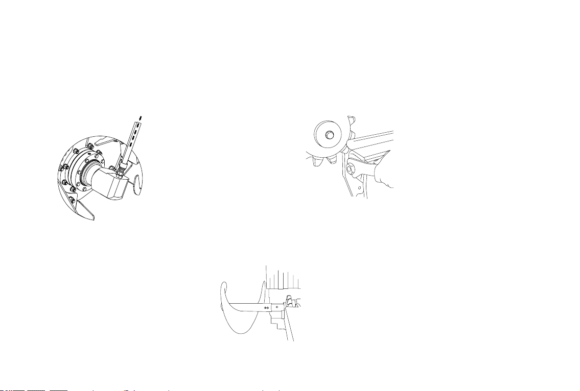
BOOMADJUSTMENT
IMPORTANT: SHUT DOWN TRENCHER & MACHINE BEFORE ANY ADJUSTMENTS ARE MADE
1. Use spanner supplied
to wind adjuster nut
clockwise for
loosening,
anti-clockwise
for tightening.
AUGERADJUSTMENT
1. The spoil removal
Auger is double
ended. When a 150mm
or 200mm chain is being
used. The Augers must
be on the correct way
around. This illustration
shows the Augers being
tted with the narrow end
closest to the chain.
1. The Trencher chain must
rotate in an anti-clockwise
direction (when viewed from
the motor side of the Trencher).
The supply line from the
parent machine must be
connected to the ‘A’ port on
the Trencher motor.
HYDRAULICHOSECONNECTION
SUPPLY FROM MACHINE

20 PM-000042-C Mini Bigfoot Trencher Operators Manual - June 2021
CHAINADJUSTMENT
1. To either adjust chain
or remove chain –
remove the ½" Bolt
holding spanner to
outer boom.
2. Use spanner supplied
to wind adjuster nut
clockwise for loosening,
anti-clockwise for
tightening.
CHAIN REMOVAL AND ASSEMBLY
TO REMOVE CHAIN; FOLLOW STEPS 1 & 2 CHAIN ADJUSTMENT
1. Use a 5mm punch to dislodge joining pin
(Frost or Diggatac chain only).
Be careful that all body parts are well
clear when performing this operation,
as the chain can swing or fall heavily.
Remove chain o sprocket and
to join the chain simply reverse the
operation. Ensure the teeth on the
chain are facing the correct direction.
8 INSTALLATION AND OPERATING INSTRUCTIONS
3. To achieve the
correct chain
tension: Adjust the
tension on the lower
chain section at the
midway point between
the sprockets to allow
20-30mm of vertical
movement.
Chain
midway point
between sprockets
20mm to 30mm
Table of contents
Other Digga Industrial Equipment manuals


