digi-tech QM-1500 User manual

HOBBYIST
Low Cost
Digital Multimeter
QM1500

2
Low Cost
Digital Multimeter User Manual
Thank you for purchasing this Low Cost Digital Multimeter. This multimeter is
the perfect introduction to meters, and data capture of standard measurements
including DC and AC voltage, DC current, resistance, transistor, and diode testing.
Just move the rotary switch to the correct position, plug in your leads and you’re
good to go!
Please familiarise yourself with the functions of the multimeter before use. We
recommend retaining this manual for ease of reference.
• Improper use of this meter can cause damage, shock, injury or death.
• Always remove the test leads before replacing the battery or fuses.
• Before using the meter, please inspect the condition of the test leads and the
meter itself for any damage. If damage is present, please discontinue use.
• Do not measure voltage if the voltage on the terminals exceeds 1000V above
earth ground.
• Use great care if voltages are greater than 30VAC RMS. Anything above this is
considered a shock hazard.
• Always discharge capacitors and disconnect power before performing diode,
resistance or continuity tests.
• Do not exceed the maximum limits of the input values shown in the
specication tables on pages 12, 13, 14 & 15 of this manual.
• Remove the batteries from the meter if it will be unused for an extended period
of time.
• Always turn the function switch to the o position when not in use.

3
FUNCTIONS
Max. Display 2000 counts
Basic Accuracy 0.500%
DC Voltage Range 400mV - 1000V
AC Voltage Range 4V - 1000V
DC Current Range 4mA -10A
AC Current Range 4mA - 10A
Resistance 400Ω - 40MΩ
Capacitance (CAP) 4nF - 100µF
Frequency (Hz) Up to 10MHz
4
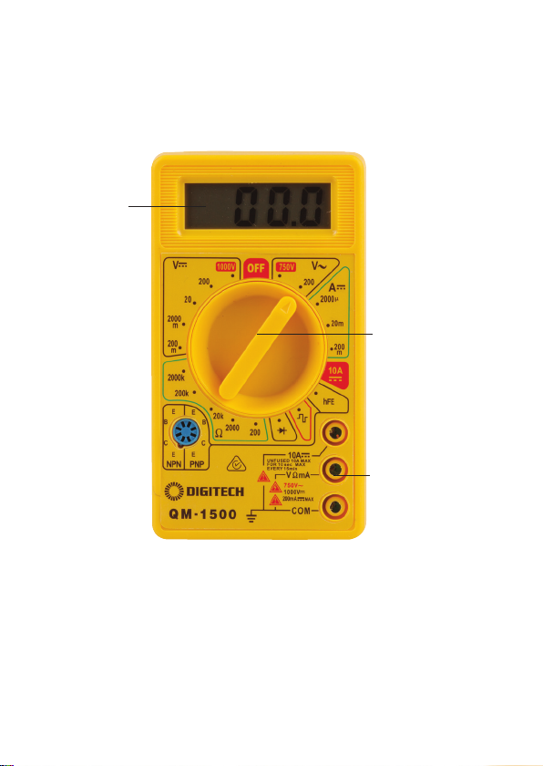
The tilt stand & battery compartment are at the rear of the multimeter.
LCD Screen
Function
Switch
COM Input Jack

5
FUNCTIONS
Autoranging/
Manual
• The meter’s default setting is autoranging. This
automatically selects the best range for the selected
test/measurement.
• To set the meter to manual, press the RANGE button.
The ‘AUTO’ icon on the screen will turn o.
• Press the RANGE button to move through the available
ranges until you see the range you want.
• To exit the manual mode and return to autoranging,
press and hold the RANGE button for 2 seconds.
• Manual ranging cannot be selected for capacitance and
frequency measurements.
Mode • The MODE button helps you to move through various
operations with various icons displayed on screen.
• It works in conjunction with the function switch to
measure things like resistance, diode, continuity and
capacitance.
• It also allows you to select between AC or DC current
measurements.
Function Switch • Select a measurement range by turning the switch to
the preferred option.
LCD Screen • Readings and measurements taken by the multimeter
will display in this area.
Hold & Backlight • Press the HOLD button to lock readings as displayed on
the screen. Press again to unlock.
• Press the HOLD button longer to turn the backlight on.
Press the button longer again to turn the backlight o.
Relative Button • Press the REL button to store a reading for referencing
at a later date. Then reference any new inputs against
the stored measurement.
• Press the REL button again to cancel the relative
measurement function.
• Not to be used for Hz/duty, diode and continuity
measurements.

6
SYMBOL DESCRIPTION
Continuity
Diode Test
Low Battery
F Farads (Capacitance)
ΩOhms
Hz Hertz (Frequency)
V Volts
A, mA, µA Current Range
AC Alternating Current/Voltage
AUTO Autoranging
DC Direct Current/Voltage
HOLD Display Hold

7
AC/DC VOLTAGE MEASUREMENT
On some low AC and DC voltage ranges - when test leads are not connected to a
device - the display on the screen may show a random, changing reading. This is
normal and caused by high-input sensitivity of the multimeter. When connected
to a circuit, the multimeter will display a stabilised, accurate measurement.
1) Set the function switch to the VAC or VDC position.
2) Insert the black test lead banana plug into the negative COM jack.
3) Insert the red test lead banana plug into the positive VΩCAP jack.
4) Use the Mode button to select AC or DC voltage.
5) Connect the test leads in parallel to the circuit under test.
6) Read the voltage in the display.
DC CURRENT MEASUREMENT
Do not measure 20A currents for longer than 30 seconds. Exceeding 30 seconds
may cause damage to the meter and/or test leads.
1) Insert the black test lead banana plug into the negative COM jack.
• For current measurements up to 4000μA DC, set the function switch to the μA
position and insert the red test lead banana plug into the μA jack.
• For current measurements up to 400mA DC, set the function switch to the mA
position and insert the red test lead banana plug into the mA jack.
• For current measurements up to 10A DC, set the function switch to the 10A
position and insert the red test lead banana plug into the 10A jack.
2) Press the MODE button to show “DC” on the screen.
3) Remove power from the circuit under test, then open up the circuit at the point
where you wish to measure current.
4) Touch the black test probe tip to the negative side of the circuit.
5) Touch the red test probe tip to the positive side of the circuit.
6) Apply power to the circuit.
7) Read the current displayed on the screen.
AC CURRENT MEASUREMENT
Do not measure 20A currents for longer than 30 seconds. Exceeding 30 seconds
may cause damage to the meter and/or test leads.
1) Insert the black test lead banana plug into the negative COM jack.
• For current measurements up to 10A, set the function switch to the 10A
position and insert the red test lead banana plug into the 10A jack.

8
• For current measurements up to 400mA, set the function switch to the mA
position and insert the red test lead banana plug into the mA jack.
• For current measurements up to 4000µA, set the function switch to the µA
position and insert the red test lead banana plug into the µA jack.
2) Press the MODE button to indicate “AC” on the screen.
3) Remove power from the circuit under test, then open up the circuit at the point
where you wish to measure current.
4) Touch the black test probe tip to the negative side of the circuit. Touch the red
test probe tip to the positive side of the circuit.
5) Apply power to the circuit.
6) Read the current displayed on the screen.
RESISTANCE MEASUREMENT
To avoid electric shock, disconnect power to the test area and discharge all
capacitors before taking any resistance measurements. Remove the batteries
and unplug the line cords.
1) Set the function switch to the Ω CAP position.
2) Insert the black test lead banana plug into the negative COM jack.
3) Insert the red test lead banana plug into the positive Ω jack.
4) Press the MODE button until “Ω” displays on the screen.
5) Touch the test probe tips across the circuit or part being tested. It is best to
disconnect one side of the part being tested so the rest of the circuit will not
interfere with the resistance reading.
6) Read the resistance displayed on the screen.
CONTINUITY CHECK
To avoid electric shock, never measure continuity on circuits or wires that have
voltage on them.
1) Set the function switch to the Ω CAP position.
2) Insert the black test lead banana plug into the negative COM jack.
3) Insert the red test lead banana plug into the positive VΩCAP jack.
4) Press the MODE button until displays on the screen.
5) Touch the test probe tips across the circuit or wire you want to check.
6) If the resistance is less than approximately 35Ω, the audible signal will sound.

9
DIODE TEST
The value that displays on screen during the diode check is the forward voltage.
1) Set the function switch to the Ω CAP position.
2) Insert the black test lead banana plug into the negative COM jack.
3) Insert the red test lead banana plug into the positive VΩCAP jack.
4) Press the MODE button until display on the screen.
5) Touch the test probes to the diode or semiconductor being tested.
6) Reverse the probe polarity by switching probe position. Note this reading.
7) The diode or junction can be evaluated as follows:
A) If one reading shows a value and the other reading shows OL, the diode is
good.
B) If both readings show OL, the device is open.
C) If both readings are very small or zero, the device is shorted.
CAPACITANCE MEASUREMENTS
To avoid electric shock, disconnect power to the area being tested and discharge
all capacitors before taking any capacitance measurements.
1) Set the function switch to the Ω CAP position.
2) Insert the black test lead banana plug into the negative COM jack.
3) Insert the red test lead banana plug into the positive VΩCAP jack.
4) Press the MODE button until “nF” displays on the screen.
5) Touch the test leads to the capacitor being tested.
6) The test may take up to three minutes or more for large capacitors to charge.
Wait until the readings settle before ending the test.
7) Read the capacitance value displayed on the screen.
TEMPERATURE MEASUREMENTS
The temperature probe is tted with a type K mini connector. A mini connector to
banana connector adaptor is supplied for connection to the input banana jacks.
1) Set the function switch to the temp position.
2) Insert the temperature probe into the input jacks, making sure to observe the
correct polarity.
3) Press the MODE button to indicate “ºF” or “ºC”.
4) Touch the temperature probe head to the part you wish to measure. Ensure
the probe remains in contact with the part until the reading stabilises (about
30 seconds).
5) Read the temperature displayed on the screen.
10
FREQUENCY MEASUREMENT
1) Set the function switch to the HZ% position.
2) Insert the black test lead banana plug into the negative COM jack.
3) Insert the red test lead banana plug into the negative VΩCAP jack.
4) Touch the test probes to the circuit being tested.
5) Read the frequency displayed on the screen.
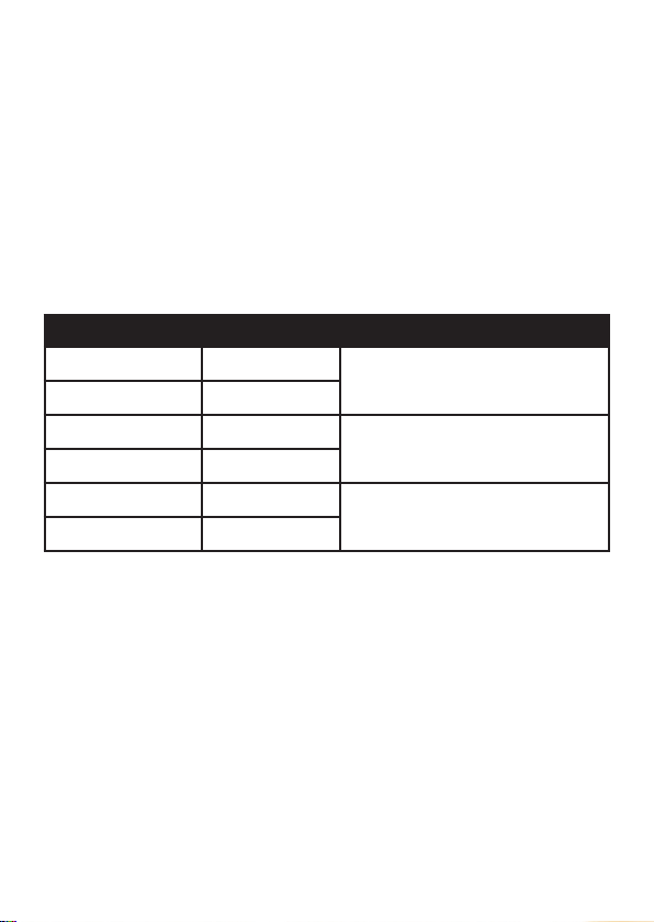
MEASUREMENT SPECIFICATIONS
The following guide is based on an environmental temperature of 18-28°C and
humidity <70%.
RANGE RESOLUTION ACCURACY
40mV/60mV 0.01mV
±(0.5% reading + 5 digits)
400mV/600mV 0.1mV
4V/6V 0.001V
±(0.8% reading + 3 digits)
40V/60V 0.01V
400V/600V 0.1V
±(1.0% reading + 5 digits)
1000V 1V
DC VOLTAGE
Input impedance: 10MΩ; Max. input voltage: 1000V DC

11
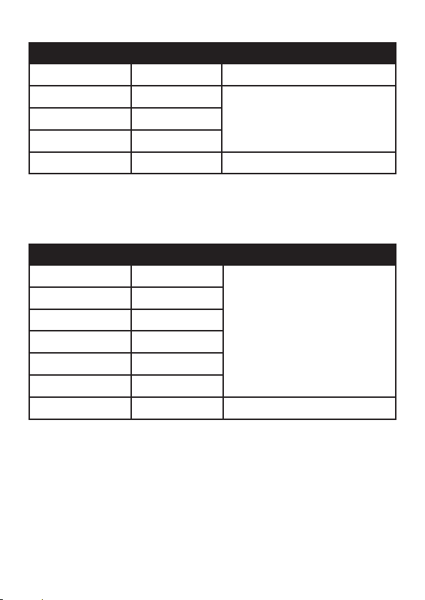
AC VOLTAGE
RANGE RESOLUTION ACCURACY
400mV/60mV 0.1mV
±(1.0% reading + 3 digits)
4V/600mV 1mV
40V/6V 10mV
400V/60V 100mV
1000V 1V ±(1.2% reading + 5 digits)
Input impedance: 10MΩ; Max. input voltage: 1000VAC RMS;
Frequency range: 50~400Hz; all AC voltage ranges are specied from 5% of range
to 100% of range.
DC CURRENT
RANGE RESOLUTION ACCURACY
400µA 0.1µA
±(1.2% reading + 3 digits)
4000µA 1µA
40mA 10µA
400mA 100µA
10A 10mA ±(1.0% reading + 3 digits)
Overload protection: fuse FF500mA/1000V and fuse F10A/1000V. Maximum
inputs: 400µA DC (µA range), 400mA DC (mA range), 10A DC (10A range).

12
RANGE RESOLUTION ACCURACY
400µA 0.1µA
±(1.5% reading + 5 digits)
4000µA 0.001mA
40mA 0.01mA
400mA 0.1mA
10A 10mA ±(3.0% reading + 5 digits)
AC CURRENT
Overload protection: fuse FF500mA/1000V fuse FF10A/500V.
Frequency range: 50~400Hz
RESISTANCE
Input protection: 1000VDC or 1000VAC RMS
RANGE RESOLUTION ACCURACY
400Ω 0.1Ω ±(0.8% reading + 5 digits)
4kΩ 1Ω
±(0.8% reading + 2 digits)40kΩ 1Ω
400kΩ 100Ω
4MΩ 1kΩ
±(2.5% reading + 8 digits)
40MΩ 10kΩ
13
RANGE RESOLUTION ACCURACY
4Hz 0.001Hz
±(1.0% reading + 3 digits)
40Hz 0.01Hz
400Hz 0.1Hz
4kHz 1Hz
40kHz 10Hz
400kHz 100Hz
5MHz 1kHz ±(1.2% reading + 4 digits)
FREQUENCY
Overload protection: 1000VDC or 1000VAC RMS.
Sensitivity >0.5V while ≤1MHz, >3V while >1MHz.
RANGE RESOLUTION ACCURACY
40nF 10pF ±(5.0% reading + 7 digits)
400nF 0.1nF
±(3.0% reading + 5 digits)
4µF 1nF
40µF 10nF
100µF 0.1µF ±(5.0% reading + 7 digits)
CAPACITANCE
Overload protection: 1000VDC or 1000VAC RMS

14
DIODE & CONTINUITY
RANGE FUNCTION
Display approximate forward voltage of diode
Built-in buzzer will sound if resistance is less than 30Ω
MAINTENANCE
BATTERY INSTALLATION
To avoid the false readings, replace the battery as soon as the low battery power
indicator appears.
1) Turn the power o and disconnect the test leads from the meter.
2) Open the rear battery cover with a screwdriver.
3) Remove the old battery and insert the new battery into the battery holder,
observing the correct polarity.
4) Put the battery cover back in place, secure with the screws.
REPLACING FUSES
1) Turn power o and disconnect the test leads from the meter.
2) Remove the battery cover.
3) Gently remove the old fuse and install the new fuse into the holder.
4) Always use a fuse of the proper size and value (0.5A/1000V fast blow for the
400mA range, 10A/1000V fast blow for the 10A range).
5) Replace and secure the cover.

15
SPECIFICATIONS
Display: 2000 Count
Security Class: CatII 500V
Basic DCV Accuracy: 0.500%
DC Voltage: 200mV, 1000V (± 0.5%)
AC Voltage: 200V, 750V (max input 750V RMS) (± 1.2%)
DC Current: 200µA, 2mA, 20mA, 200mA, 10A (± 1.2%)
Resistance: 200Ω, 2kΩ, 20kΩ, 200kΩ, 2MΩ (± 1.2%)
Measurement Type: Average
Input Impedence: 1Ω
Dimensions: 125{H) x 68(W) x 23(H)mm
Weight: 140g
Battery Type: 1.9V (included)
BOX CONTENTS
1 x Multimeter
1 x Test Leads
1 x 9V Battery
1 x User Manual

16
Distributed by:
TechBrands by Electus Distribution Pty. Ltd.
320 Victoria Rd, Rydalmere
NSW 2116 Australia
Ph: 1300 738 555
Int’l: +61 2 8832 3200
Fax: 1300 738 500
www.techbrands.com
Table of contents
Other digi-tech Multimeter manuals


