Steren MUL-020 User manual

Product / Producto: POCKET
DIGITAL MULTIMETER /
MULTÍMETRO DIGITAL TIPO
ESTUCHE
Model / Modelo: MUL-020
Brand / Marca: Steren
CONDICIONES
1. Para hacer efectiva esta garantía se requiere: La presentación de esta póliza y del producto, en el lugar en donde fue adquirido o en ELECTRONICA STEREN S.A. DE C.V.
2. ELECTRONICA STEREN S.A. DE C.V. se compromete a reparar el producto en caso de estar defectuoso sin ningún cargo al consumidor.
3. El tiempo de reparación en ningún caso será mayor a 30 días contados a partir de la recepción del producto en cualquiera de los sitios en donde pueda hacerse efectiva la
garantía.
4. El lugar donde puede adquirir partes, componentes, consumibles y accesorios, así como hacer válida esta garantía es: En cualquiera de las direcciones arriba mencionadas.
ESTA GARANTIA NO ES VALIDA EN LOS SIGUIENTES CASOS:
1. Cuando el producto ha sido utilizado en condiciones distintas a las normales.
2. Cuando el producto no ha sido operado de acuerdo con el instructivo de uso.
3. Cuando el producto ha sido alterado o reparado por personas no autorizadas por ELECTRONICA STEREN S.A. DE C.V.
Nota: El consumidor podrá solicitar que se haga efectiva la garantía ante la propia casa comercial, donde adquirió el producto. Si la presente garantía se extraviara, el
consumidor puede recurrir a su proovedor para que le expida otra póliza de garantía, previa presentación de la nota de compra o factura respectiva.
DATOS DEL DISTRIBUIDOR
DISTRIBUTION / NOMBRE / DISTRIBUIDOR:
ADDRESS / DOMICILIO:
PRODUCT / PRODUCTO: BRAND / MARCA:
MODEL / MODELO: SERIAL NUMBER / No. DE SERIE:
DATE OF DELIVERY / FECHA DE ENTREGA:
Call Center / Centro de Atención a Clientes
del Interior 01 800 500 9000
Mexico City / Cd. de México: 53 54 22 90
This Steren product is warranted under
normal usage against defects in
workmanship and materials to the original
purchaser for one year from the date of
purchase.
Garantiza este producto por el término de
un año en todas sus partes y mano de
obra contra cualquier defecto de fabricación
y funcionamiento, a partir de la fecha de
entrega.
Warranty
CONDITIONS:
1. This warranty card with all the required information, the invoice or purchase ticket, the product box or package, and the product, must be presented with the
product when warranty service is required.
2. If the product stills on the warranty time, the company will repair it free of charge even the transportation charges.
3. The repairing time will not exceed 30 natural days, from the day the claim was received.
4. Steren sells parts, components, consumables and accessories to customer, as well as warranty service, at any of the following addresses:
THIS WARRANTY IS VOID ON THE NEXT CASES:
If the product has been damage by an accident, acts of God, mishandling, leaky batteries, failure to follow enclosed instructions, improper repair by unauthorized
personal, improper safe keeping or otherwise.
Notes:
a) The customer can also claim the warranty service on the purchase establishment.
b) If you lose the warranty card, we can reissue it just showing the invoice or purchase ticket.
Póliza de Garantía

INSTRUCTIVO DE USO DE MULTÍMETRO DIGITAL TIPO ESTUCHE
Producto: MUL-020
Marca: Steren
Antes de utilizar su nuevo Multímetro Digital lea este instructivo
para evitar cualquier mal funcionamiento. Guárdelo para futuras
referencias.
INSTRUCCIONES DE SEGURIDAD
Siempre revise y esté seguro de que el switch funcional esté en la posición
apropiada.
Para evitar una descarga eléctrica, cuando esté midiendo altos voltajes
hágalo con precaución.
Siempre desconecte el circuito que se encuentra bajo prueba antes de
conectar las puntas de prueba.
Asegúrese de que todo voltaje CA (~) o CD ( ) esté desconectado
(OFF) cuando esté haciendo medidas de resistencia (Ohms).
Nunca utilice éste multímetro con la batería terminada.
Nunca opere el multímetro más de la máxima tolerancia indicada.
VOLTÍMETRO DE CD ( )
Rango Resolución Precisión
2V 1 mV + (0,5 % lectura + 2 dígitos)
20V 10 mV + (0,5 % lectura + 2 dígitos)
200V 100 mV + (1,0 % lectura + 2 dígitos)
450V 1V + (1,0 % lectura + 2 dígitos)
Capacidad máxima de entrada: 450 VDC ( )
VOLTÍMETRO DE CA (~)
Rango Resolución Precisión
200 100 mV + (1,8 % lectura + 2 dígitos)
450 1V + (1,8 % lectura + 2 dígitos)
Capacidad máxima de entrada: 450 Vrms (~)
Rango de frecuencia: 40-400Hz
AMPERÍMETRO DE CD ( )
Rango Resolución Precisión
200 100 µ A + (1,0 % lectura + 2 dígitos)
Capacidad máxima de completa escala: 0,3V
Protección de Sobrecarga: Fusible de 200mA / 250V
OHMMETRO
Rango Resolución Precisión
2K 1 Ohm + (1,2 % lectura + 2 dígitos)
20K 10 Ohm + (1,2 % lectura + 2 dígitos)
200K 100 Ohm + (1,2 % lectura + 2 dígitos)
2000k 1K Ohm + (1,2 % lectura + 2 dígitos)
ESPECIFICACIONES GENERALES
Método de medición: Modo integrado doble (analógico / digital)
Display: 3,5 dígitos LCD (0-1999)
Polaridad: Automático indicado polaridad negativa.
Velocidad toma de muestra: 2-3 veces por segundo.
Indicador de batería baja: Marcada en pantalla
Temperatura de Operación: 0°C - 40°C, menos de 80% de humedad.
Dimensiones: 112 x 62 x 23 mm
Peso: 980 g incluyendo baterías
Batería: 12V (GP-23A)
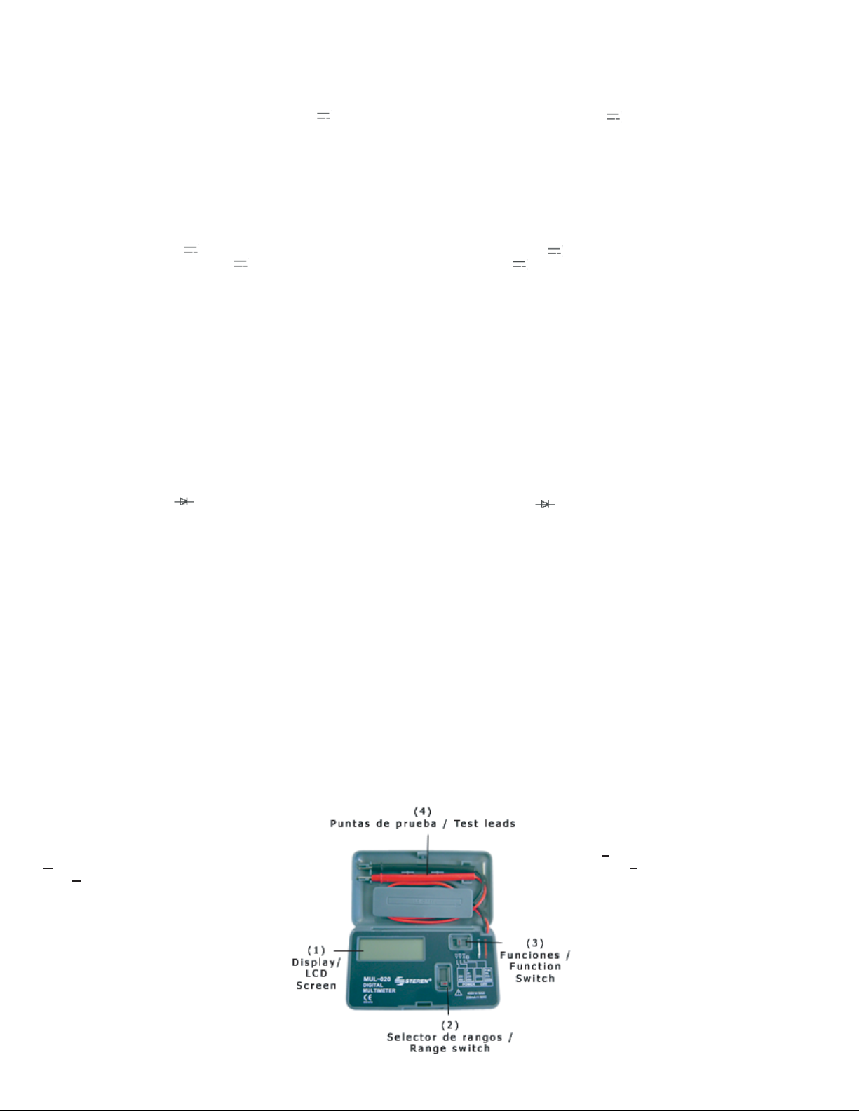
INSTRUCTIVO DE OPERACIÓN
VOLTÍMETRO DE CD (V )
1.- Seleccione en funciones el modo V
2.- Seleccione el rango de la perilla en la posición deseada. Si la magnitud
del voltaje es de antemano desconocido, ponga la perilla de rango en la
escala más alta y entonces reducir hasta que la lectura en el display sea
satisfactoria.
3.- Conecte las puntas de prueba a el aparato o circuito que va a ser
medido.
INSTRUCTION MANUAL FOR POCKET DIGITAL MULTIMETER
Product: MUL-020
Brand: Steren
Before using your new Pocket Digital Multimeter, please read this
instruction manual to prevent any damage. Put them away in a
safe place for future references.
SAFETY INSTRUCTIONS
Always check that the function switch is in the correct position.
To avoid shock hazard , do the high voltage measures, carefully.
Always disconnect the tested circuit before connecting testing leads.
Make sure that every voltage AC (~) or DC ( ) is OFF, when you are
doing resistance measures.
Never use this multimeter with low charge battery.
Never operate this multimeter over the maximal indicated tolerance.
DC VOLTAGE ( )
Range Resolution Accuracy
2V 1 mV + (0,5 % rdg + 2 digits)
20V 10 mV + (0,5 % rdg + 2 digits)
200V 100 mV + (1,0 % rdg + 2 digits)
450V 1V + (1,0 % rdg + 2 digits)
Maximum allowable input: 450 VDC ( )
AC VOLTAGE (~)
Range Resolution Accuracy
200 100 mV + (1,8 % rdg + 2 digits)
450 1V + (1,8 % rdg + 2 digits)
Maximum input capacity: 450 Vrms (~)
Frequency Range: 40-400Hz
DC AMMETER ( )
Range Resolution Accuracy
200 100 µ A + (1,0 % rdg + 2 digits)
Maximum complete scale capacity: 0,3V
Overload protection: 200mA / 250V fuse
OHMMETER
Range Resolution Accuracy
2K 1 Ohm + (1,2 % rdg + 2 digits)
20K 10 Ohm + (1,2 % rdg + 2 digits)
200K 100 Ohm + (1,2 % rdg + 2 digits)
2000k 1K Ohm + (1,2 % rdg + 2 digits)
GENERAL SPECIFICATIONS
Measure method: Double integrated mode (analog / digital)
Display: LCD screen 3,4 digits (0-1999)
Polarity: Automatic negative polarity
Measure speed: 2 to 3 times per second
Battery indicator: On screen
Operating environment: 0°C to 40°C, less than 80% humidity
Dimensions: 126 x 62 x 23 mm
Weight: 980 g (battery included)
Power: 12V (GP-23A)
OPERATIONAL MANUAL
DC VOLTIMETER (V )
1.- Select V Mode.
2.- Set range switch to desired DCV position. If magnitude of value is
unknowable, set the switch to highest range and reduce it until you obtain
a satisfactory reading.
3.- Connect test lead to device or circuit being measured.

Notes:
1.- On screen appears if the polarity is correct.
2.- When appears "1" on screen, it means that the range is higher or
exists an overload. You must change the range and verify the allowable
input at the multimeter (450 V ), otherwise you may cause damage to
the equipment.
AC VOLTIMETER (~)
1.- Select V~ Mode.
2.- Set range switch to desired ACV position
3.- Connect test lead to device or circuit being measured. Remember that
the multimeter display the polarity as overload (1) and allowable input on
this function is 450 V~.
DC AMMETER (A )
1.- Select A Mode.
2.- Set range switch to 200mA
3.- Connect test lead to device or circuit being measured. Never connect
the leads into devices with 200mA or higher.
4.- Read current value on Digital Display.
OHMMETER
1.- Select Ω Mode.
2.- Set range switch to desired Ωposition
3.- If the resistance being measured is connected to a circuit, turn off the
power and discharge all capacitors, before applying test probes.
4.- Connect test leads to resistance being measured.
DIODE TESTER
1.- Select ΩMode.
2.- Set 2k range .
3.- Connect read lead to the anode of the diode under test and black lead
to the cathode.
4.- Read current value on Digital Display. If the connection is reversed,
only figure "1" will be displayed.
BATTERY REPLACEMENT
1.- When the battery is empty or diminish the voltage operation, a symbol
appears on screen.
2.- Turn the multimeter off and remove the test leads of every measured
circuits.
3.- Remove the screws located in the bottom of the case and open the
box. Replace the battery and check the correct polarity.
FUSE REPLACEMENT
To replace the fuse, remove the screws located in the bottom of the case
and open it. Replace the fuse with a new one.
CAUTION
1.- Make sure that the test leads are disconnected from any test circuit,
and the power switch is in OFF, before opening the box.
2.- To prevent fire, install the fuse only with AMP/ Voltage, as the original
(200mA / 250V).
MEASUREMENT SPECIFICATIONS
Accuracy / error
+ (% reading + number of digits).
23°C + 5°C, less than 75% humidity.
PANEL DESCRIPTION
1.- LCD screen
2.- Range switch
3.- Functions switch
4.- Test leads
Notas:
1.- En el display le indicará si la polaridad es correcta.
2.- Cuando el display muestre "1" quiere decir que el rango es más alto o
que existe una sobrecarga por lo que deberá cambiar la escala o rango
más alto y verificar la capacidad del multímetro (450 V ), de lo contrario
podría dañarlo.
VOLTÍMETRO DE CA (V ~)
1.- Seleccione en funciones el modo (V~)
2.- Seleccione el rango de la perilla en la posición deseada.
3.- Conecte las puntas de prueba al aparato que va a ser medido.
Recuerde que el multímetro le indicará la polaridad como sobrecarga (1) y
que la capacidad en ésta función es de 450 V~
AMPERÍMETRO DE CD (A )
1.- Seleccione en funciones el modo A
2.- Seleccione el rango en 200mA.
3.- Conecte en serie las puntas de prueba al aparato que va a ser medido,
nunca conecte las puntas a un aparato con una carga máxima de 200mA.
4.- La lectura del valor de la corriente y la polaridad se obtendrán en el
display.
OHMMETRO
1.- Seleccione en funciones el modo Ω
2.- Seleccione el rango de la perilla en la posición deseada.
3.- Si la resistencia a ser medida está conectada a un circuito apague todo
y descargue todos los capacitores antes de aplicar con las puntas de
prueba.
4.- Conecte las puntas de prueba, una de cada lado de la resistencia que
va a ser medida.
PROBADOR DE DIODOS
1.- Seleccione en funciones el modo Ω.
2.- Seleccione el rango 2K .
3.- Conecte la punta roja en el ánodo del diodo que va a ser probado y la
negra al cátodo.
4.- La lectura del voltaje se obtendrá en el display. Si la conexión del diodo
es contraria, sólo aparecerá en el display "1".
REEMPLAZO DE BATERÍAS
1.- Cuando las baterías estén agotadas o que la operación de voltaje
disminuya, un símbolo aparecerá en el display.
2.- Apague el multímetro y quite las puntas de prueba de todos los
circuitos de prueba anteriores para reemplazar la batería.
3.- Quite los tornillos del respaldo trasero y abra la caja. Reemplace la
batería, asegurándose de la polaridad correcta.
REEMPLAZO DE FUSIBLE
Para reemplazar el fusible, quite los tornillos del centro del respaldo de la
caja y ábrala. Reemplace el fusible con uno del mismo tipo.
PRECAUCIÓN
1.- Asegúrese de que las puntas de prueba estén desconectadas del
circuito de prueba y que la perilla de rango esté en OFF antes de que abra
la caja.
2.- Para prevenir un incendio, instale el fusible únicamente con AMP /
Voltaje igual al original (200mA / 250V)
ESPECIFICACIONES DE MEDICIÓN
Exactitud o ausencia de error
+ (% lectura + el número de dígitos)
23°C + 5°C, menos del 75% de humedad.
DESCRIPCIÓN DEL PANEL
1.- Pantalla de LCD
2.- Selector de Rangos
3.- Selector de funciones
4.- Puntas de prueba
Other Steren Multimeter manuals

Steren
Steren MUL-095 User manual

Steren
Steren MUL-055 User manual

Steren
Steren MUL-052 User manual

Steren
Steren MUL-107 User manual

Steren
Steren MUL-115 User manual

Steren
Steren MUL-050 User manual

Steren
Steren MUL-605 User manual

Steren
Steren MUL-280 User manual

Steren
Steren MUL-100 User manual

Steren
Steren MUL-016 User manual

Steren
Steren MUL-400 User manual

Steren
Steren MUL-030 User manual

Steren
Steren MUL-010 User manual

Steren
Steren MUL-005 User manual

Steren
Steren MUL-057 User manual

Steren
Steren MUL-035 User manual

Steren
Steren MUL-005 User manual

Steren
Steren MUL-283 User manual

Steren
Steren MUL-650 User manual

Steren
Steren MUL-010 User manual