TIS TIS258 User manual
Instruction Manual Version 2.00
0
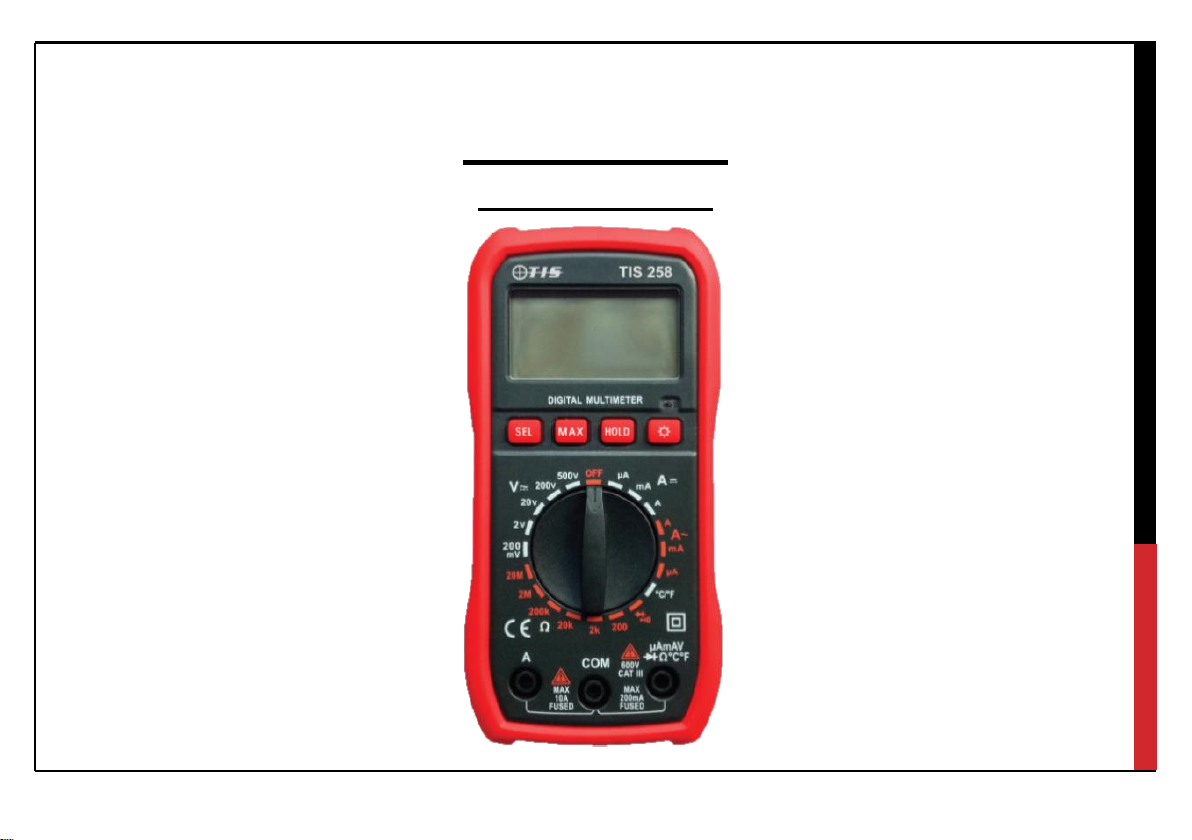
TIS258
Digital Multimeter

1
CONTENTS:
1.0 Introduction ------------------------------------------------------------------------------------------------------------ 2
2.0 Accessories -------------------------------------------------------------------------------------------------------------3
3.0 Safety Instructions ----------------------------------------------------------------------------------------------------3
3.1 Safety Symbols----------------------------------------------------------------------------------------------------4
3.2 Warranty-------------------------------------------------------------------------------------------------------------5
4.0 Instrument Layout, display information & symbols-------------------------------------------------------------6
5.0 Description of Measurement Operation --------------------------------------------------------------------------7
5.1 AC/ DC Voltage Measurement -------------------------------------------------------------------------------------7
5.2 AC/DC Current Measurement --------------------------------------------------------------------------------------8
5.3 Diode Measurement --------------------------------------------------------------------------------------------------8
5.4 Continuity Indication / Buzzer Test --------------------------------------------------------------------------------8
5.5 Resistance Measurement --------------------------------------------------------------------------------------------9
5.6 Temperature Measurement ------------------------------------------------------------------------------------------9
6.0 Technical Specifications ----------------------------------------------------------------------------------------------10-15
7.0 Installation / Replacement of Battery & Fuse Protection -----------------------------------------------------16

2
1.0-Introduction
Thank you for purchasing the TIS258
The TISS258 Digital Multimeter, is a 31/2-digit multimeter with the following capabilities / functionality:
Function
Range
Function
Max. Display
2000 counts
Diode
Yes
Basic Accuracy
0.5%
Continuity
Yes
DC Voltage
200mV-500V
Data Hold
Yes
AC Voltage
200mV-500V
Back Light
Yes
DC Current
200µA-10A
Auto Power off
Yes
AC Current
200µA-10A
Manual Range
Yes
Resistance
200-20M
Battery
9V x 1
Temperature
-20℃-750℃
Diode
Yes
-4℉-1382℉
Continuity
Yes

3
2.0 –Accessories
Test lead(s) (Red + Black) ----------------------------------------------------------------------------2
9V PP3 alkaline battery---------------------------------------------------------------------------- 1
User Manual ------------------------------------------------------------------------------------------ 1
3.0- SAFETY INSTRUCTIONS
Warning –Please read and follow the following:
Before using the instrument, test leads and / or the adaptors please ensure there are no signs of damage
as this could result in electrical shock and / or inaccurate results.
Once the battery indicator appears, please replace the battery. As low battery level can produce
inaccurate results.
Do not use / store the instrument in high temperature, humid, flammable, or electromagnetic
environments as this could result in injury, damage to the instrument and / or inaccurate results.
If the instrument / equipment is use in a manner not specified by the manufacturer, the protection
provided by the instrument may be impaired.
Do not connect test leads to live systems or hazardous voltages unless stated within the manual.

4
3.1 Safety Symbols
Warning & caution safety label
Double insulation
DC (Direct Current)
AC (Alternating Current)
Low battery
Dangerous high voltage!
Buzzing on-off
Earthing
Comply with EC standard
Applicable to test and measuring circuits connected at the
source of the building's low-voltage MAINS installation.
CAT IV

5
3.2 - Warranty
NEW INSTRUMENTS HAVE A WARRANTY PERIOD OF: 1 YEAR FROM THE DATE OF PURCHASE
BY THE USER.
(A copy of the original purchase invoice may be requested to validate the purchase date).
This warranty period includes parts and labor only.
Any unauthorized repair / adjustment will void the warranty.
For service / calibration / repair requirements, please contact:
TEST INSTRUMENT SOLUTIONS LIMITED
UNIT 12/14, LUDDITE WAY BUSINESS PARK
RAWFOLDS WAY
CLECKHEATON
BD19 5DQ
Tel: 01274 752407
Email: SALES@TIS-TIC.CO.UK
6
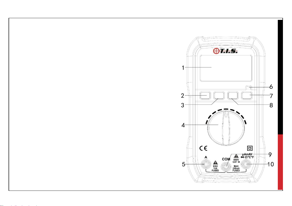
4.0 Instrument Layout, display information & symbols
1. LCD display
2. Select Button (Switch the measurements of AC,
DC current; Temperature, Diode & Continuity check)
3. MAX Hold button
4. Rotary/ Function Selector Switch
5. 10A, Input Terminal
6. LED Indicator
7. Backlight Button
8. Data Hold Button
9. COM, Input Terminal
10. V,Ω,mA, Input Terminal

7
5.0 - Description of Measurement Operation
AC / DC Voltage Measurement
1) Set the rotary switch to the voltage position. (V / V~)
2) If required press the select button to change the voltage sine wave from DC V to AC (V~)
3) Insert the black test lead banana plug into the negative COM input terminal & insert the red
test lead banana plug into the positive V/ΩmA input terminal.
4) Connect test leads to the conductors to be tested.
5) Read the voltage in the LCD display.
PLEASE NOTE: That the polarity of red test lead must be connected to the positive conductor
to indicate the positive voltage measurement when conducting DC voltage measurements.
8
AC/DC Current Measurement
1) Select the rotary switch to the appropriate current measurement function & range.
2) Insert black test lead banana plug into the negative COM input terminal.
3) To perform current measurements less than 200mA insert the red test lead banana plug into
the mA Input terminal or for current measurement between 200mA to 10A insert the red test
lead banana plug into 10A input terminal
4) Disconnect the circuit under test then connect the test leads in series with the circuit.
5) Turn the power on and read the measurement value displayed.
If OL (Over Limit) is displayed, increase the measurement range / function.
Diode Test
1. Set the rotary switch to the “ ” position.
2. Connect the black test lead to the "COM" terminal and the red test lead to the "VΩ:" input terminal.
3. Pres the “SEL” button to select the diode function (If required)
4. Connect the test leads to the diode, test both the “Forward Bias & Reverse Bias” of the diode under test.
Open circuit measurements will be indicated as OL on the display,
Continuity Indication / Buzzer Test
1. Set the rotary switch to the “ ” position.
2. Connect the black test lead to the "COM" terminal and the red test lead to the "VΩ:" input terminal.
3. Pres the “SEL” button to select the continuity function (If required)
4. Connect test leads to the circuit under test.
5. Measurement will be displayed and the audible indicator will sound, when measurements are under 70Ω.

9
Resistance Measurement
1. Set the rotary switch to the required resistance range.
2. Insert the black test lead banana plug into the negative COM input terminal & insert the red
test lead banana plug into the positive V/ΩmA input terminal.
3. Connect test leads / probes to the measuring points
4. Read resistance measurement displayed on the LCD.
If OL (Over Limit) is displayed, increase the measurement range / function.
Temperature Measurement
1. Set rotary switch to the “°C°F” function.
2. Select the measurement type by press the “SEL” button.
3. Connect the thermocouple by inserting the black lead in to the COM input terminal & insert
the red lead in to the V/ΩmA input terminal.
4. Place the thermocouple either on or in the vicinity of the object / room under test.
5. Wait while measurement stabilizes.
6. Read temperature measurement displayed on the LCD.

10
6.0 –Technical Specifications
DC Voltage
Overload Protection:
200mV Range at 250V AC/DC
Other ranges at 600V AC/DC
Range
Resolution
Accuracy
200mV
100V
±0.5% reading ± 3 digits
2V
1mV
±0.8% reading ± 3 digits
20V
10mV
200V
100mV
500V
1V
±1.0% reading ± 5 digits

11
AC Voltage
Range
Resolution
Accuracy
200mV
0.1mV
±0.5% reading ± 3 digits
2V
1mV
±0.8% reading ± 3 digits
20V
10mV
±0.8% reading ± 3 digits
200V
0.1V
±0.8% reading ± 3 digits
500V
1V
±1.2% reading ± 5 digits
Overload Protection: 600V AC/DC
Frequency range: 40~400Hz

12
DC Current
Range
Resolution
Accuracy
200µA
0.1µA
±1.0% reading ±5 digits
2mA
1µA
20mA 10µA
200mA 100µA ±2.0% reading ±5 digits
2A
1mA
±2.5% reading ±5 digits
10A
10mA
Overload protection: fuse F200mA; fuse F10A

13
AC Current
Range
Resolution
Accuracy
200µA 0.1µA ±1.8% reading ±3 digits
2mA 1µA
±1.5% reading ±5 digits
20mA
10µA
200mA 100µA ±2.5% reading ±5 digits
2A 1mA
±3.0% reading ±10 digits
10A 10mA
Overload protection: fuse F200mA; fuse F10A

14
Resistance
Range
Resolution
Accuracy
200Ω
0.1Ω
±1.2% reading ±2 digits
2kΩ
1Ω
±1.0% reading ±2 digits
20kΩ
10Ω
±1.0% reading ±2 digits
200kΩ
100Ω
±1.0% reading ±2 digits
2MΩ
1kΩ
±1.0% reading ±2 digits
20MΩ
10kΩ
±1.2% reading ±8 digits

15
Diode and Continuity
Range
Function
Display approximate forward voltage of diode
Built-in buzzer will be sounded if resistance is less than
70Ω±30Ω
Temperature
Range
Resolution
Accuracy
-20℃~ 750℃
1℃
±2.0% reading ±3 digits
-4℉~ 1832℉
1℉
±3.0% reading ±3 digits

16
7.0 - Installation / Replacement of Battery & Fuse Protection
WARNING:
●To avoid electric shock, disconnect the test leads from any source of voltage before removing
the back cover or the battery or fuse covers.
●To avoid electric shock, do not operate the meter until the battery and fuse covers are in
place and fastened securely.
Battery Installation / Replacement.
To avoid the false readings, replace the battery as soon as the battery indicator appears.
1) Turn power off and disconnect the test leads from the meter.
2) Open the rear battery cover..
3) Insert the battery into battery holder, observing the correct polarity.
4) Put the battery cover back in place & secure.
Replacing the Fuse(s)
1) Turn power off and disconnect the test leads from the meter.
2) Remove the battery cover and the battery.
3) Remove the screws securing the rear cover.
4) Remove the defective fuse and install an identical fuse. (F200mA or F10A Fuse)
5) Replace and secure the rear cover, battery and battery cover.
Table of contents
Other TIS Multimeter manuals


