DigiCare LifeWindow Lite LW8 User manual


Operators Manual Multi-parameter Patient Monitor " LifeWindow Lite LW8 " 1
Table of Contents
Section 1 -Introduction
A. About this Manual .......................................... ….2
B. Manufacture's Responsibility .........................….2
C. Warranty ........................................................….2
D. General Safety .............................................. ….2
E. Unpacking and Accessories .......................... ….3
Section 2 –Quick Start
A. Description .....................................................….4
B. Turning-On ..........................................................8
C. Alarm and Pulse Sound...................................….8
D. Patient Management.............................................8
E. Date and Time.......................................................9
F. Monitoring Screen.................................................9
G. Traces Setting.......................................................9
H. Patient Type..........................................................9
I. ECG Monitoring ...................................................10
J. SpO2 Monitoring...................................................10
K. CO2 Monitoring....................................................10
L. NIBP Monitoring....................................................11
M. Temperature Monitoring.......................................11
N. Invasive Pressure Monitoring...............................12
O. FIO2 Monitoring……............................................12
P. Trends……. ........................................................13
Q. Discharge Patient and Save Data………………..13
R. Battery Operation .........................…………..……13
B. Turning-OFF…......................…………………......14
Section 3 –Print, Reports and Networking
A.. Printing and Reports……………………………...14
B. Networking..........................………………………16
Section 4 -ECG Monitoring
A. Patient Connections............……………….………24
B. ECG Scale .........................................................26
C. Lead Selection.....................................................26
D. ECG Filter…… ...................................................26
E. Heart Rate Limits.................................................26
F. ECG Seep Speed.................................................27
G. ECG Pulse Test...................................................27
H. ECG Patient Type................................................27
I. ECG Alarms...........................................................27
Section 5 –Pulse Oximetry Monitoring
A. Patient connections .......................................….28
B. SpO2 monitoring ...........................................….29
C. SpO2 Waveform and Bar-graph...........................31
D. SpO2 Alarm Limits ..............................................31
E. SpO2 Alarm Messages .......................................31
Section 6 -CO2 Mainstream Monitoring
A. Overview……………..…...............…….................32
Section 6.1 -CO2 Mainstream Monitoring
A. Principle of Operation …...............…………….....32
B. Indications for Use....................……………….......32
C. Patient Connections…..………………………........33
D. Monitoring CO2 …………..…………………...........36
Section 6.2 -CO2 Sidestream Monitoring
A. Principle of Operation …...............………….........38
B. Indications for Use ............................……..…........38
C. Patient Connections ..………………………............39
D. Monitoring CO2………………………………...........43
Section 7-NIBP Monitoring
A. Cuff Selection and Placement...........……..……….45
B. NIBP Monitoring....................................................48
C. NIBP Alarm Messages.………………….………….49
Section 8-Temperature Monitoring
A. Patient Connections.........................................…..49
B. Temperature Monitoring..................................…..50
Section 9-Invasive Pressure Monitoring
A. Pressure Transducer......................................…..50
B. Transducer Connection...................................…..51
C. IP Scale and Label……...................................…..52
D. Trigger Source…….…….......................................53
E. Pulsatile / Static Mode….…….........................…..53
F. Transducer Zero…….……...............................…..53
G. IP Alarm Limits…….……......................................54
H. IP Alarm Messages…….……..........................…..54
Section 10 –Fraction of Inspired Oxygen
A. Principle of Operation ..........................................54
B. Patients Connections .................................... …..54
C. Calibration.......................................................…..56
D. FIO2 Monitoring.. ............................................…..56
Section 11 -Technical Specification
A. Mechanical Description ................................. …..58
B. Power Requirements ...........................................58
C. ECG ..............................................................…..58
D. SpO2 Pulse Oximeter .....................................…..59
E. Non-Invasive Blood Pressure................................59
F. Temperature………………...............................…..59
G. CO2………..……………….....................................60
H. Invasive Pressure..………………....................…..61
I. FIO2.………..………………...............................…..61
J. Display ………..............................………….………61
K. Environment Specifications ...........................…..61
L. Trends ...........................................................…..61
M. Auxiliary Output (Rear Panel) ........................…..62
Section 12-Maintenance
A. The Monitor ....................................................…..62
B. Probes ........................................................... …..62
C. Patient Cables ................................................…..63
D. Battery ...........................................................…..63
Warranty Terms & Conditions ........................ …..64
Rev5Jan 10

Digicare Biomedical Technology
Operators Manual Multi-parameter Patient Monitor " LifeWindow Lite LW8 " 2
SECTION 1 –INTRODUCTION
A. ABOUT THIS MANUAL
This operator’s manual has been prepared to provide information on the correct use of the
LifeWindowLite LW8 multi-parameter patient monitor. It contains performance specifications,
installation, operation and maintenance information. It is intended for trained health-care
professionals.
B. MANUFACTURER’S RESPONSIBILITY
• The manufacturer of this equipment is responsible for the effects on safety, reliability, and
performance of the equipment only if:
• The equipment is used in accordance with the instructions in this manual.
• The electrical installation complies with all applicable regulations.
• Assembly operations, extensions, re-adjustments, or repairs are carried out by person’s
authorized by the manufacturer.
Incorrect operation or failure of the user to maintain the monitor in accordance with
proper maintenance procedures relieves the manufacturer or his agent from all
consequent non-compliance, damage or injury.
• It is up to the user to ensure that any applicable regulations respecting the installation and
operation of the monitor be observed.
C. WARRANTY
All products manufactured by Digicare Biomedical Technology Inc. are warranted to be free
from defects in material and workmanship and to operate within published specifications, under
normal use, for a period of one year from date of original shipment. The warranty on
accessories is ninety (90) days.
If an examination by Digicare, discloses such products or component parts to be defective, then
our obligation is limited to repair or replacement (at our option).
D. GENERAL SAFETY
1 -INDICATIONS
The LifeWindowLW8 Lite series is a Class 1 device designed for continuous operation in
accordance with the Safety Standard EN60601-1.The Class 1 device MUST BE connected to
the external protective conductor to be operated with the external MAINS LINE. It is intended for
use by person’s trained in professional health care, in the hospital / clinic environment. The
operator must be thoroughly familiar with the instructions in this manual before using the
instrument.
The unit is configured to measure and monitor the following available parameters:
• ECG Waveform (3 and 5 leads);
• Heart Rate (HR) from ECG ;
• ECG arrhythmia and ST segment analysis (5 Leads ECG);
• Blood oxygen saturation (SpO2or pulse oximetry);
• SpO2 waveform (Plethysmogram);

Digicare Biomedical Technology
Operators Manual Multi-parameter Patient Monitor " LifeWindow Lite LW8 " 3
• Two Temperature channels;
• Two Invasive Pressure channels;
• Pulse (from SpO2 ,NIBP, IP1 or IP2) rate;
• NIBP Systolic, Diastolic and mean arterial pressure;
• End-tidal CO2 concentration (EtCO2) –Mainstream or Sidestream;
• Inspired CO2 concentration (inCO2) –Mainstream or Sidestream;
• Respiration rate (from EtCO2 waveform);
• Inspired Fraction of O2 ( FIO2 );
CONFIGURATIONCODE
Electrocardiogram –3 Lead ECG........................................................................................E
Electrocardiogram –5Lead ECG.......................................................................................5E
Pulse Oximetry and Plethysmogram ................................................................................. S
FIO2 –Inspired Fraction of Oxygen ................................................................................. F
CO2 -Sidestream Capnography ................................................................................. C
CO2 -Mainstream Capnography ............................................................................. M
CO2 DualCap –Mainstream and Sidestream Capnography ..............................................D
Non-invasive Blood Pressure -NIBP .......................................................................... N
Invasive Pressure (up to two channels) ......................................................................... #P
Temperature (up to two channels) ......................................................................................#T
The applied parts are classified accordingly to the degree of electrical isolation from the patient
and defibrillation protection.
•The ECG patient connection is DEFIBRILLATION PROOF type CF applied part.
•The Invasive Pressure connection is type CF applied part and is not DEFIBRILLATION
PROOF.
•The Temperature connection is type BF applied part and is not DEFIBRILLATION PROOF.
•The SpO2 is type BF applied part and is not DEFIBRILLATION PROOF.
•All other patient connections are NOT DEFIBRILATION PROOF type B applied part.
2 -CAUTIONS
The LifeWindow™ Lite LW8 was designed and tested accordingly to the ELECTRO-MAGNETIC
COMPATIBILITY Standard IEC601-1-2. However, the operator is responsible to verify if the
monitor is been affected or affecting others electrical equipment. Equipments like electrocautery
and image scanners can generate interference and cause degradation of the
LifeWindow™ Lite LW8 performance. To avoid this situation, it should be installed as far as
possible of those equipment.
3-CONTRAINDICATIONS
The LifeWindow™ Lite LW8 series is NOT intended to be used during MRI (magnetic
resonance imaging).
The LifeWindow™ Lite LW8 is NOT suitable for use in the presence of a flammable anaesthetic
mixture with air or with oxygen or nitrous oxide.
E. UNPACKING AND ACCESSORIES
Carefully remove the monitor and its accessories form the shipping carton. Save the packing
materials in case the monitor must be shipped or stored. Ensure your LifeWindowLite LW8
has the items listed in the SHIPPING LIST inside the carton.
Digicare Biomedical Technology
Operators Manual Multi-parameter Patient Monitor " LifeWindow Lite LW8 " 4
SECTION 2–QUICK START
A. DESCRIPTION
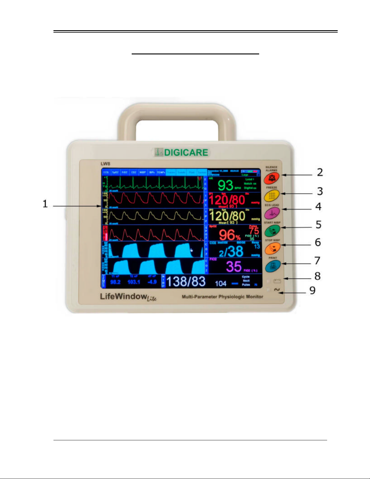
1 –FRONT PANEL
FIG.1
1-TFT Active Matrix Color Flat Panel Display: Windows based Graphic Interface displays 6
user selectable physiologic waveforms, numeric values, indicators, alarm messages and
physiologic parameters menu.
2-ALARM DISABLE dedicated pushbutton.
3-FREEZE TRACES dedicated pushbutton.
4-ECG LEAD SELECTION dedicated pushbutton.
5-NIBP START dedicated pushbutton.
6-NIBP STOP dedicated pushbutton.
7-PRINT dedicated pushbutton.
8-BATTERY charge status LED indicator.
9-AC mains line LED indicator.
Digicare Biomedical Technology
Operators Manual Multi-parameter Patient Monitor " LifeWindow Lite LW8 " 5
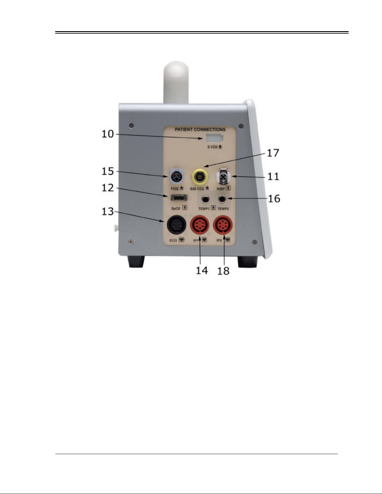
2 –PATIENT CONNECTIONS PANEL
FIG. 2
10-Internal CO2 Sidestream module receptacle. Accept sample line to Sidestream CO2 and
Respiration Rate determination and monitoring.
11-NIBP hose receptacle. Accept cuff to Non Invasive Blood Pressure and Pulse determination
and monitoring.
12-SpO2 connector. Accepts pulse oximetry patient sensor cable to non-invasive determination
and monitoring of the blood oxygen content.
13-ECG connector. Accepts ECG cable for electrocardiogram and Heart Rate monitoring.
14-Invasive Pressure Channel 1 connector. Accepts pressure transducer cable to invasive
determination and monitoring of blood pressure.
15-FIO2 connector. Accept cable and sensor to Inspired Fraction of Oxygen determination and
monitoring, using an air way adaptor.
16-Temperature Channel 1 and Channel 2 connectors. Accepts temperature cable and sensor
for non-invasive Temperature determination and monitoring.
17-CO2 External Sidestream or Mainstream module connector. Accepts CO2 mainstream cable
connector. Also accepts External Sidestream module cable connector, for determination and
monitoring of CO2 and Respiration Rate.
18-Invasive Pressure Channel 2 connector. Accepts pressure transducer cable to invasive
determination and monitoring of blood pressure.

Digicare Biomedical Technology
Operators Manual Multi-parameter Patient Monitor " LifeWindow Lite LW8 " 6
3 –REAR PANEL
FIG.3
19-On / Standby switch. Momentary contact switch to turn-on and off the unit. To turn-on the
unit, double click this switch.
20-Video Connector. Connection to a standard CRT video.
21-Keyboard Connector. PS2 connection to a standard AT type keyboard used only to service
purposes.
22-Auxiliary Connector. Supply analog output signals, trigger signals and one RS232
communication port.
23-Ethernet Connector. Connection to Ethernet network standard.
24-Mains Line IEC connector. Accepts power cable from mains line. Have 1 main fuse and 1
spare fuse inside.
25-General Power switch. Interrupt power from internal battery and mains power supply.
26-Antenna for wireless networking.
27-USB 1 and USB 2 connectors.
28-Internal CO2 Sidestream Vent port. Keep it always open to room air.
Digicare Biomedical Technology
Operators Manual Multi-parameter Patient Monitor " LifeWindow Lite LW8 " 7
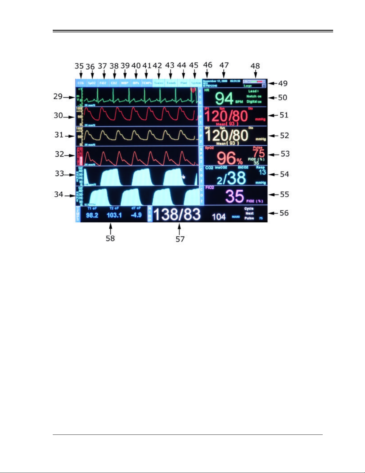
4 –MONITORING SCREEN
FIG.4
29 –First waveform user selected area, showing ECG waveform in Thin Line Style, scale
(-1 to +1mV), sweep speed of 25mm/s and QRS detected INDICATOR (HEART).
30 –Second waveform user selected area, showing Invasive Pressure 1 waveform in Thin Line
Style, scale (0 to 180mmHg), sweep speed of 25mm/s.
31 –Third waveform user selected area, showing Invasive Pressure 2 waveform in Thin Line
Style, scale (0 to 180mmHg), sweep speed of 25mm/s.
32 –Fourth waveform user selected area, showing SpO2 waveform in Thin Line Style, with
Pulse Level strength scale (1 to 8), sweep speed of 25mm/s.
33 –Fifth waveformuser selected area, showing Capnogram (CO2) waveform in Fill In Style,
with scale (10 to 50mmHg), sweep speed of 12.5mm/s.
34 –Sixth waveform user selected area, showing Capnogram (CO2) waveform in Fill In Style,
with scale (10 to 50mmHg), sweep speed of 12.5mm/s.
35 –ECG menu selection.
36 –SpO2 menu selection.
37 –FIO2 menu selection.
38 –CO2 menu selection.
39 –NIBP menu selection.
40 –Invasive Pressure menu selection.
41 –Temperature menu selection.
42 –Traces configuration menu selection.
43 –Trends menu selection.
44 –Print menu selection.
45 –System configuration menu selection.

Digicare Biomedical Technology
Operators Manual Multi-parameter Patient Monitor " LifeWindow Lite LW8 " 8
46 –Patient Name and ID indicator
47-Date and Time indicators.
48 –Battery Status Indicator.
49 –Adult / NeonatalMode selector and indicator.
50 –ECG Heart Rate (BPM) and ECG settings.
50 –Invasive Pressure 1 Indicator and IP1 settings.
51 –Invasive Pressure 2 Indicator and IP2 settings.
53 –SpO2 Indicator in % and SpO2 settings.
54 –Indicators and settings: End tidal CO2 (EtCO2) value display in %.
Inspired CO2 (InsCO2) value display in %.
Respiration Rate in RPM.
55 –FIO2 Indicator in % and settings:
56 –Indicators: NIBP mode selected indicator: Manual, Stat or Auto.
NIBP cycle interval selected indicator.
NIBP time to next cycle remaining indicator.
57 –Indicators: Systolic arterial pressure determined by NIBP in mmHg.
Diastolic arterial pressure determined by NIBP in mmHg.
Mean Arterial Pressure (MAP) determined by NIBP in mmHg.
58 –Temperature Indicators and settings
B. TURNING-ON
• Plug the AC power cord in AC MAINS receptacle at rear panel connector (24) and in the AC
outlet. The LifeWindow™ Lite LW8 accepts 110 or 220 VAC with automatic selection by the
power supply.
• The electrical installation of the room must have three pin outlets with earth connection for
protection of patient, users and equipment.
• The AC-ON LED indicator will light green and the BATTERY status indicator will light green if
the battery is fully charged or yellow if charging.
• Power-on the unit by double-clicking the ON switch ( 19 ) on the rear panel.
• The monitor will then perform a “boot” sequence (approx. 1.5 min.).
C. ALARM AND PULSE SOUND
• When the unit turns-on, the Alarm Sound is disabled by 2 minutes.
• To disable the Alarm Sound for more 2 minutes press and release the “Alarm Sound”
dedicated pushbutton ( 2 ) in the front panel. The AUDIBLE ALARMSOFF message flashes in
screen.
• To permanently disable the Alarm Sound press and hold 4 seconds the “Alarm Sound”
dedicated pushbutton ( 2 ). The AUDIBLE ALARMS OFF message is displayed steady on
screen.
• The Pulse and Alarm sound volume levelsare set to default levels. To change the Pulse and
Alarm Sound volume level, touch in System menu and Sound Volume. Select the Beep
Volume, Alarm Volume and Beep Source, if it is from the ECG, SpO2 or OFF (no Beep).
D. PATIENT MANAGEMENT
• the LifeWindow™ Lite LW8 starts the monitoring screen and start storing all Vital Signs.
• The “Patient Management” screen can be opened at any time by touching the “System” menu.
• The “Patient Management”screen is automatically displayed when the monitor is turned-on
with two options: “Admit New Patient” and “Cancel Pat Mangmt”.
• Touching “Cancel Pat Mangmt”, closes the “Patient Management” screen.
• Although the Patient can be admitted at a later time, we recommend to admit the Patient
before Patient data starts to be stored to prevent losing Patient Data.

Digicare Biomedical Technology
Operators Manual Multi-parameter Patient Monitor " LifeWindow Lite LW8 " 9
• To admit a patient, touch on the “Admit New Patient” button.
•Enter the Patient’s Name and Patient Control ID.
• Touch the “Admit Patient & Start Monitoring” button.
• If less then 5 minutes of monitoring occurred, the Patient is admitted and the screen is closed.
• If more then 5 minutes of data is available, you need to choose what to do with the with the
patient’s data in the buffer, with three options:
• “Keep for the new patient”. Touch to include data to new patient.
• “Save as different patient”. Touch to save data to different patient.
• “Discard Data”. Touch to discard.
E. DATE AND TIME
• Check if the current “Date and Time” displayed in the Indicator (47) are correct.
•To change the Date and Time, touch the “SYSTEM” menu and touch “Date/Time Settings”.
•Set current location “Date and Time”. Touch OK to finish.
F. MONITORING SCREEN
• The LifeWindow™ Lite LW8 monitoring screen is pre-configured accordingly to the Vital Signs
parameters that are installed and turned-on. The traces are pre-configured to keep “In-line
Logic” with the Indicators area in the right of the traces area.
•To turn-off any Vital Sign that is not going to be used in patient’s monitoring, touch the Vital
Sign menu and touch ECG OFF or SPO2 OFF, etc. The monitoring screen may change some
Traces settings and Indicators.
• Factory Default Settings are configured to standard applications. As the user changes Alarm
Limits and other settings, the LifeWindow™ Lite LW8 will save the changes when turned-off.
Next time the unit is turned-on, the last saved settings will remain.
• To return the unit to the Factory Defaults, touch in the “System” menu and touch in “Load
Factory Default Settings”.
G. TRACES SETTING
• The LifeWindow™ Lite LW8 six traces are configured and cascaded accordingly to the Vital
Signs parameters installed and turned-on.
• You can select any physiological waveform from one to six of the available traces. You can
also cascade the traces up to 3 individual loops.
•Move the Pointer to TRACES icon and press the Select pushbutton.
•Select TRACE waveform source (ECG, SpO2 Plethysmogram, Capnogram, or No Selection).
•Select TRACE sweep speed (6.25mm/s, 12.5mm/s, 25mm/s, 50mm/s or 100mm/s).
•Select TRACE color.
• Select TRACE style (Thin line or Fill In).
• Press the Cascade Traces button if you want to cascade two or more traces.
• You can create until 3 cascade loops: Loop 1, Loop 2 and Loop 3. Select the Loop
waveform Source. Select the Sweep Speed, Color and Style for each trace.
•Press the Done button to finish.
• Note: When the LifeWindow™ Lite LW8 is turned-off and turned back on, the traces will return
to the original pre-configuration accordingly to the physiological parameters that are installed
and turned-on, to keep “In-line Logic” with the Indicators area in the right of the traces area.
H. PATIENT TYPE
• Patient Type has two modes: Adults and Neonatal. It affectsthe ECG and NIBP functions only.
All other Vital Signs functions are not affected by the Patient Type selected.

Digicare Biomedical Technology
Operators Manual Multi-parameter Patient Monitor " LifeWindow Lite LW8 " 10
• Selection of Patient Type shall be based on the Patient’s Heart Rate range for ECG monitoring
and Cuff size to be used for NIBP monitoring.
Adult Patient Type : ECG Heart Rate Range: 5to 220 BPM
NIBP Cuff Size #: 5, 7, 8, 9, 10 and 11
Neonatal Patient Type : ECG Heart Rate Range: 30 to 350 BPM
NIBP Cuff Size #: 1, 2, 3, 4 and 6
I. ECG MONITORING
• The ECG function is pre-configured with the following default settings. To change the ECG
settingstouchthe ECG menu and change the desired setting.
Heart Rate High Limit : 140 BPM
Heart Rate Low Limit : 60 BPM
Heart Rate Averaging : 8 Beats for Adult, 16 Beats for Neonatal
ECG Scale : -0.5 mV to +1.0 mV
ECG Filter Mains Notch : ON
ECG Filter Digital : ON
ECG Lead Selection : II
•Prepare the electrode sites in the standard configuration for RA (Right Arm), LA (Left Arm)
and LL (Left Leg). Application sites should be clean and dry. Shave or clip excess hair if
necessary. Use conductive ECG gel if necessary.
• Connect the 3 Leadwires to the ECG cable. Connect the ECG cable to the receptacle (13) in
the patient panel. Install the 3 electrodes in the patient. More details in Section 4.
• A visual indicator (♥) and a beep Sound indicates R wave detection and the ECG waveform
and Heart Rate reading are displayed.
J. SpO2 MONITORING
• The SpO2 function is pre-configured with the following default settings. To change the SpO2
settings touch the SpO2 menu and change the desired setting.
SpO2 % High Limit : OFF
SpO2 % Low Limit : 88%
SpO2 Pulse High Limit : 140 BPM
SpO2 Pulse Low Limit : 60 BPM
• Choose the SpO2 sensor type and prepare the SpO2 sensor and clip.
• The preferred sensor application site is the finger. Alternatively, the sensor and clip may be
applied to patient’s ear, hand or foot.
• Connect the sensor assembly to the SpO2 Patient Cable:
• Plug the SpO2 Patient Cable into the SpO2 connector (12) on the side panel of the monitor.
Push the cable in until you hear an audible “click”.
• The yellow SpO2 SENSOR message changes for the green Searching SpO2 message, the
Bar-graph shows the SpO2 Pulse Level, the SpO2 waveform, SpO2 % and Pulse Rate
values are displayed.
K. CO2 MONITORING
• The LifeWindow Lite LW8 automatically startsthe CO2 function when CO2 sensor is
connected to the unit.
• The CO2 function is pre-configured with the following default settings. To change the CO2
settings touch the CO2 menu and change the desired setting.
CO2 Waveform Scale : 0 to 50 mmHg
EtCO2 High Limit : 45 mmHg

Digicare Biomedical Technology
Operators Manual Multi-parameter Patient Monitor " LifeWindow Lite LW8 " 11
EtCO2 Low Limit : 20 mmHg
InsCO2 High Limit : 10 mmHg
InsCO2 Low Limit : OFF
Resp Rate High Limit : 50 BPM
Resp Rate Low Limit : 5 BPM
• Select the appropriate airway adapter for mainstream or sample line with adapter for
sidestream based on the patient and monitoring situation.
• Connect the sample line with adapter to receptacle (10) in the Patient Panel, or;
• Connect the sample line with adapter to the External Sidestream module and connect the
module to connector (17) in the Patient Panel, or;
• Connect the Mainstream sensor assembled in the airway adapter to connector (17).
• Wait for the “Sensor Warm Up” message to clear. If the “Zero Required” message is
displayed, proceed with a Zero Calibration Procedure as explained in Sections 6.1 and 6.2.
• Connect the airway adapter to the patient’s air way assembled circuit.
L. NIBP MONITORING
• The NIBP function is pre-configured with the following default settings. To change the NIBP
settings touch the NIBP menu and change the desired setting.
NIBP Cycle Mode : Manual
NIBP Systolic Upper Limit : 160 mmHg
NIBP Systolic Lower Limit : 100 mmHg
NIBP Diastolic Upper Limit : 100 mmHg
NIBP Diastolic Lower Limit : 60 mmHg
NIBP Mean Upper Limit : 120 mmHg
NIBP Mean Lower Limit : 80 mmHg
NIBP Pulse Upper Limit : 140 BPM
NIBP Pulse Lower Limit : 60 BPM
• The widest cuff that can be placed on the patient, without extending beyond the joint, should
be selected. Cuff width should be 40 –60% of limb circumference. The cuff should be
wrapped for a snug fit.
•The monitor comes standard with six different sizes of cuffs. They are marked to aid in proper
cuff selection. When a cuff is wrapped around a site, its index edge should be in the range
indicated on the cuff. The cuff is too small or too large if the index edge is outside the range.
• For best results, a cuff should be wrapped for a snug fit and be positioned reasonably close to
heart level.
• Avoid compression or restriction of the NIBP Inflation Hose. The hose must not be kinked or
pinched. It can be placed in any position, but it should be kept off the table surface to avoid
equipment vibrations.
•The cuff should not be applied on a limb being used for an intravenous infusion. Do not place
the cuff on any extremity being used for SpO2 monitoring.
M. TEMPERATURE MONITORING
• The Temperature function is pre-configured with the following default settings. To change the
Temperature settings touch the TEMPs menu and change the desired setting.
Temperature Channel 1 : On
Temperature Channel 2 : OFF
Temperature Unit : °F
Temperature 1 Upper Limit : 100.4°F (38.0 °C)
Temperature 1 Lower Limit : 95.9°F (35.5 °C)
• To enable Temperature 2 channel, touch in TEMPs menu, Temperature 2 and select ON.
• To enable Differential T1-T2, touch in TEMPs menu, Differential T1-T2 and select ON.

Digicare Biomedical Technology
Operators Manual Multi-parameter Patient Monitor " LifeWindow Lite LW8 " 12
• Connect the temperature patient cable to receptacle (16 ) Temperature 1 or Temperature 2.
• In the Temperature menu select Temperature1, Temperature2 or T1-T2.
• The temperature value is displayed when the probe temperature is in the 50 to 122 °F (10 to
50°C), range otherwise the temperature display is blanked.
N. INVASIVE PRESSURE MONITORING
• The Invasive Pressure function is pre-configured with the following default settings. To change
the Invasive Pressure settings touch the IBPs menu and change the desired setting.
IP # : OFF
IP # Scale : 0 to +150 mmHg
IP # Mode : Pulsatile
IP # Label : IP #
IP # Trigger Source : Pulse
IP # Systolic Upper Limit : 160 mmHg
IP # Systolic Lower Limit : 60 mmHg
IP # Diastolic Upper Limit : 160 mmHg
IP # Diastolic Lower Limit : 60 mmHg
IP # Mean Upper Limit : 120 mmHg
IP # MeanLower Limit : 60 mmHg
• The Invasive Pressure Channels 1 and 2 are turned off in the factory default settings, to avoid
alarms when not in use.
• Turn-on Invasive Pressure Channel 1 or 2 touching in the IBPs menu.
• The message “NO TRANSDUCER” is displayed until a Transducer is connected.
• Connect the pressure transducer cable to connector IP1 (14) or IP2 (18).
• Connect the catheter to the pressure transducer.
• Install the flow system and maintain the entire system with liquid.
• Hold the transducer at the heart level (axial line). Additional information in Section 9.
• The message “ZERO TRANSDUCER” is displayed until a zero calibration is executed.
• Open the TRANSDUCER input to the air (Local Atmospheric Pressure). Touch in the IBP
menu and touch in the Invasive Pressure 1 or 2. Touch the Zero Xducer button.
• If the transducer Zero calibration procedure was successful, the Invasive Pressure waveform
shall be displayed at ZERO baseline and the Invasive Pressure readings are displayed.
• If the transducer Zero calibration procedure was NOT successful, the “IP# ERROR
ZEROING” message is displayed on screen.
O. INSPIRED FRACTION OF OXYGEN MONITORING
• The FIO2 function is pre-configured with the following default settings. To change the FIO2
settings touch the FIO2 menu and change the setting.
FIO2 function : OFF
FIO2 Upper Limit : OFF
FIO2 Lower Limit : 20 %
• Turn-on the FIO2 function touching the FIO2 menu and select ON.
• Connect one end of the FIO2 patient cable into the jack receptacle on the back end of sensor.
• Connect the other end of the cable into the receptacle (15) located on the patient connections
panel of the unit.
• The LifeWindow™ Lite LW8 should be calibrated before each use and every 8 hours to
maintain maximum accuracy. See Section 10 for more information.
• The LifeWindow™ Lite LW8 can be used to measure a gas mixture for oxygen in two basic
modes:
• In the inhalation side of breathing circuit ahead of humidifiers and medicating devices or other
instances where gases are flowing to a patient in breathing circuits. When monitoring oxygen

Digicare Biomedical Technology
Operators Manual Multi-parameter Patient Monitor " LifeWindow Lite LW8 " 13
in breathing circuits, the flow diverter must be used.
•In confined volumes such as tents and hoods. In these applications the flow diverter must be
removed from the sensor so that it does not interfere with the rapid exchange of gases to and
from the sensing surface of the sensor.
• Never install the sensor in a location that will expose the sensor to patients exhaled breath or
secretions unless you intend to dispose of the sensor and flow adapter after use.
P. TRENDS
•The LifeWindow™ Lite LW8 stores all measured parameters from patient, every minute since
the monitoring screen starts until the monitor is turned-off.
•The stored values can be visualized in tabular or graphic form, for trend analysis.
•Touch the “Trends” menu.
•Touch in “Tabular” to visualize all values trends in a tabular form, with indication of values
measurement time.
•Touch in “Graphical” to select display all stored physiologic values in graphic trends format.
•Touch the period of time to display the Trends: 15min, 1H, 4H, 12H, 24H, 48h e 72h.
•The Trends for all measured physiologic parameters are displayed simultaneously.
•Touch in the windows maximize button to increase the trends screen size.
•Use the cursor to move the Trends up, down, right or left.
Q. DISCHARGE PATIENT AND SAVE DATA
• At the end of monitoring, touch the “System” menu and “Patient Management” menu. Touch
“Discharge Patient” button. Press “Yes” to confirm. Press “Yes” to save the patient data. Make
sure the selected directory is the desired place to save the data (default is c:\Patient Data).
• To save to a different directory in a network computer, touch the “Select Another Directory”
button. Select the desired directory in the “Look” in field and touch the “Done” button.
• Touch the “Save Report” button to save the report to the selected directory.
R. BATTERY OPERATION
•The LifeWIndow Lite LW8 internal battery has autonomy to approximately 30 minutes of
operation when fully charged.
•The CHARGE STATUS LED indicator ( 8 ) stays yellow when battery is recharging, green
when the battery is fully charged and Off when the battery is disconnected or during battery
operation.
•With the monitor ON, the battery status indicator ( 48 ) displays the battery charge status of
the battery.
•In battery operation, the LOW BATTERY alarm message is triggered when there is charge to
approximately 10 minutes of operation. After 5 minutes with LOW BATTERY message, the
unit shut-down.
S. TURNING-OFF
•To Shut down the unit just press and release the ON / Standby (19) pushbutton on the rear
panel or touch the Shutdown option in the system menu. A screen asking to confirm if you
want to shutdown the unit is displayed.
•If any problem occurs with the shutdown function, the user can shut-off the unit by pressing
and hold the ON / Standby (19) pushbutton for 15 seconds. In this option patient data is lost.

Digicare Biomedical Technology
Operators Manual Multi-parameter Patient Monitor " LifeWindow Lite LW8 " 14
SECTION 3–PRINT, REPORTS AND NETWORKING
A. PRINTING AND REPORTS
•The LifeWindow Lite LW8 can connect to any external windows based printer,connected to
the rear panel of the unit USB 1 or 2 connector (27), or to a network printer.
•The Epson C88 Plus is installed as default printer. It also printsto a PDF virtual printer
creating PDF print reports.
• An optional Strip Chart Recorder can be installed in the unit.
1 –EXTERNAL PRINTER
• The Epson C88 Plus printer is pre-configured with the following default settings. To change
the printer settings touch the Print” Menu and select “Printer and PDF”.
• To install another Local or Network printer, read Section 3 F.
ECG Trace Settings
Printer DPI : 360 DPI Printers
Charting Speed : 25 mm/s
Scales : 5 mm/mV
Grid : Grid On
Tabular Reports
Interval Between Measurements (minutes) : 1
Numbers of Pages to Print : 1
(45 measurements / Page)
•Set the “Print DPI”. Default is set to 360 DPI (Epson). Other manufacturer uses 300 DPI.
Check your printer documentation to verify correct DPI.
• Set “Charting Speed”. Options are: 6.25, 12.5, 25, 50, 100 and 200 mm/s.
•Set “Scale”. Changing scale will change the amplitude of the ECG in the printout. Options are:
2.5, 5, 10, 20, 40, 80 and 160 mm/mV. As you increase the “Scale”it will increase the size of
the ECG in the printout.
•Set “Grid”On (default) or Off.
•Set “Interval Between Measurements” (minutes), for “Tabular Reports” printout.
•Set “Numbers of Pages to Print”. Each page has 45 measurements.
•Touch the “Print ECG to Printer” button to start printing in the installedprinter. The printout will
have the last 10 seconds of ECG followed by current time ECG.
•Touch the “Print ECG to PDF” button to create a PDF printout of the ECG. The printout will
have the last 10 seconds of ECG followed by current time ECG.
•Touch the “Print Report to Printer” to print the “Tabular Report”in the installed printer.
•Touch the “Print Report to PDF” to create a “PDF Tabular Report”.
2 –STRIP CHART RECORDER (Optional)
• The Strip Chart Recorder is pre-configured with the following default settings. To change
the printer settings touch the Print” Menu and select “Strip Chart”.
ECG Trace Settings
Charting Speed : 25 mm/s
Scales : 20 mm/mV
Grid : Grid On
Triggering Events : OFF
Tabular Reports
Interval Between Measurements (minutes) : 1
Numbers of Pages to Print : 1
(45 measurements / Page)

Digicare Biomedical Technology
Operators Manual Multi-parameter Patient Monitor " LifeWindow Lite LW8 " 15
• The Tabular Reports “# measurements in memory” is displayed in the Strip Chart Setup.
• The Tabular Reports “# of pages that can be printed” is displayed in the Strip Chart Setup.
•Select the charting speed to the ECG trace :6.25mm/s, 12.5mm/s, 25mm/s or 50mm/s.
•Select the “Grid”ON or OFF to be printed with the ECG waveform.
•Select the “ECG Scale”:2.5mm/mV, 5mm/mV, 10mm/mV, 20mm/mV, 40mm/mV, 80mm/mV
or60mm/mV.
•Activate or disable the “Triggering”events to automatically start printing the ECG in case of an
ECG alarm.
•Press the “PRINT” (7) button in the Front Panel overlay or the “Start Charting” button in the
“Strip Chart Setup” to start printing the ECG waveform on the Strip Chart Recorder.
•Press the Print Report button in the “Strip Chart Setup” to print the report in the Strip Chart.
•Press the “Stop Recorder” button in the “Strip Chart Setup” to stop printing.
3 –EXCEL REPORTS
• The LifeWindow Lite LW8 Excel report contains a Tabular Report and Trends Graphical
Report.
• The Tabular Report stores the patient’s Vital Signs every minute. The Report can be
reconfigured at the moment of printing, changing the time between readings from 1 minute up
to 99 minutes.
• The Graphical Trends Report has options for 2, 4 and 24 Hours graphic trends report.
• To generate a Excel Report the patient shall be admitted in the Patient Management Setup.
SAVING PATIENT VITAL SIGNS TO EXCEL REAPORT.
• As soon the LifeWindow™ Lite LW8 start the monitoring screen, the patient’ data is being
stored.
• Admitting the patient, transfers these data to the patient’s buffer. The patient can be admitted
any time after start monitoring.
• To save the patient’s data touch in the “System” menu and touch in the “Save Patient Vital
Signs Report”. If the current patient is not admitted at this time, an “Error –No Patient has
been admitted” screen is displayed. Touch “OK” and follow the steps to “Admit Patient”.
• If the current patient is admitted the “Save Vital Signs Report” screen is displayed. The
“Current Selected Directory” to save the patient data is displayed (default is c:\Patient Data),
with the “Report File Name”. The “Report File Name” contains the “Patient’s ID” and the date
and time of the Report generation.
• To save to a different directory in a network computer, touch the “Select Another Directory”
button. Select the desired directory in the “Look in”field and touch the “Done” button.
• Touch the “Save Report” button to save the report to the selected directory.
VIEWING PATIENT’S VITAL SIGNS EXCEL REPORT.
• To view the Patient’s Vital Signs Excel Report, touch in the “System“ menu and touch in the
“View Reports with MS Excel”.
• In the Microsoft Excel™ screen, touch in “File” and “Open”. All saved Excel reports will be
listed. Touch in the desired report name to select it and touch in “Open”.
• The Excel Report has three “tabs”: Tabular, 2 Hour, 4 Hour and 24 Hour. The Tabular report
default time interval is 5 minutes. To print the Tabular Report with the default time interval
touch in the “Printer” icon or in “File” and “Print”. In the “Print” screen touch to select the
desired printer and touch “OK”.
• To change the Excel Report time interval, touch in the “maximize” button in the top right
corner to expand the report screen. Using the right arrow button, move the Tabular Excel
Report to the left. Using the “Up” and “Down” big arrows, change the “Measurement Interval in
Minutes”. Touch in the “Click here to renewthe interval of Measurement” button. The Excel

Digicare Biomedical Technology
Operators Manual Multi-parameter Patient Monitor " LifeWindow Lite LW8 " 16
Report will change to the selected interval.
• To view the Graphical Trends Report, touch in the 2 Hours, 4 Hours or 24 Hours “tab” in the
bottom of the Microsoft Excel™ screen.
B. Networking
The LifeWindow™ Lite LW8 can be connected to your local network using Ethernet and wireless LAN.
The Ethernet connector (23) is standard in all units.
Note: Digicare Biomedical Technology Inc can supply WIFI cards for your Life Window Lite
LW8. Contact sales and support for more information on this at 561-689-0408.
1-LIFEWINDOW LITE LW8 SETUP
Turn on the LifeWindow monitor
•Move the touch screen mouse pointer to the TRACES icon on the top of the monitor screen.
•Hold down the FREEZE and NIBP Start buttons and touch the TRACES icon simultaneously.
(This will cause the LW program to stop and start the Windows Desktop.)
2-WINDOWS XP SETUP
To change the computer name, to join a domain or workgroup, or to add a computer description for a
Windows XP-based computer, use the Computer Name tab in the System Properties dialog box. To
locate this tab, use one of the following methods:
•Click Start, Settings click Control Panel, double-click System.
•Click Start, click Run, type sysdm.cpl, and then click OK.
3-CHANGE COMPUTER NAME AND JOIN A DOMAIN OR A WORKGROUP
To change a computer name and to join a domain or a workgroup, follow these steps.
Warning Before you change a computer's membership from a domain to a workgroup, be sure
that you
know the user name and the password for an account in the local Administrators group.
You cannot log on after you remove the computer from the domain
1. Click the Computer Name tab, and then click Change.
2. Type the new computer name in the Computer name dialog box.
3. Type the new domain or workgroup in either the Domain dialog box or the Workgroup dialog
box.
4. Click More to change the primary Domain Name System (DNS) suffix.
5. Click OK three times, and then restart the computer.
4-ADD ACOMPUTER DESCRIPTION
To add a computer description, type a name or a description in the Computer description box on the
Computer Name tab, and then click Apply.
Network ID Wizard
If you do not know how to complete these tasks, you can use the Network Identification (ID) Wizard to
help you. To start the Network ID Wizard, follow these steps:
1. In the System Properties dialog box, click Network ID. (Refer to steps 1-5 under Change the
Computer Name to find Systems Property)
Note This wizard is new to Windows XP. With this wizard, you can add the computer to a
workgroup or to a domain.
2. Move backward and forward in the wizard by using the Back and Next buttons.

Digicare Biomedical Technology
Operators Manual Multi-parameter Patient Monitor " LifeWindow Lite LW8 " 17
The first set of options in the Network ID Wizard is as follows:
•Option 1
"This computer is part of a business network, and I use it to connect to other computers at
work."
•Option 2
"This computer is for home use and is not part of a business network."
If you select option 1, the following options appear:
•Option 1a
"My company uses a network with a domain."
•Option 1b
"My company uses a network without a domain."
If you select option 1a, a dialog box appears that requests the following information:
•User name
•Password
•User account domain
•Computer name
•Computer domain
If you select option 1b, you can also configure the computer as a "Workgroup Member," and you can
type the name of the workgroup.
If you select option 2, you are prompted to click Finish to restart the computer. If you follow this step,
the computer is configured as a "Workgroup Member." By default, the name of the workgroup is
"Workgroup."
Then, the next page requires the domain name to which the computer is to be added. Also, the next
page requires the username and the password of an account that has the rights to add a computer to
the domain. Additionally, the next page enables the user account from the previous page to be added
to this computer. Finally, the next page enables the new user to have various rights on the local
computer.
The user may be added to the following built-in groups on the local computer:
•Administrators
•Backup operators
•Debugger users
•Guests
•HelpServicesGroup
•Network configuration operators
•Power users
•Remote desktop users
•Replicator
•Users
Note If the computer is a member of a domain, the computer also maintains a local domain that has
security accounts. If the Domain box does not appear, click theOptions button to display the Domain
box, and then select the required domain from the menu.
The first step to discuss printing is to install a local print device. A local print device could take many
forms –an inkjet printer, a local laser printer, or a label printer. The printer could be connected to the
machine in a number of ways –USB, parallel, Bluetooth, or infrared.

Digicare Biomedical Technology
Operators Manual Multi-parameter Patient Monitor " LifeWindow Lite LW8 " 18
5 INSTALLING A LOCAL PRINTER
Most local printers, when connected via USB, will initiate a Plug’n’Play installation of the printer driver.
Occasionally, we are required to install the printer manually:
1. Connect the printer to the PC and power both on.
2. Click Start, Settings and then Printers and Faxes.
3. Click Add a printerin the taskbar on the left.
4. Click Next.
5. Click Next for a local printer attached to the computer.
6. Windows will search for a Plug’n’Play printer. If it does not find one, click Next.
Digicare Biomedical Technology
Operators Manual Multi-parameter Patient Monitor " LifeWindow Lite LW8 " 19
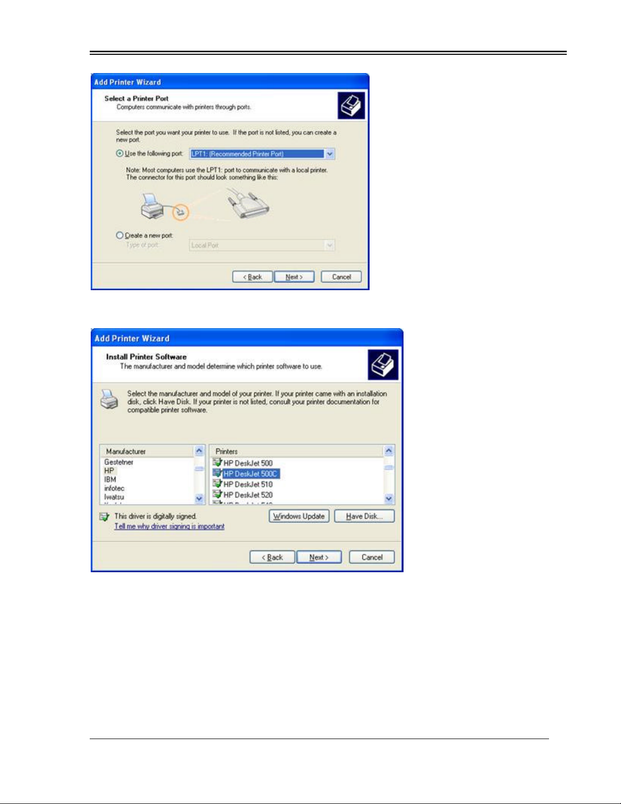
7. Select the port you have the printer plugged into and click Next.
8. Select the Manufacturer on the left and the Printer on the right. Click Next.
Table of contents
Popular Measuring Instrument manuals by other brands

CARLO GAVAZZI
CARLO GAVAZZI LDM 35 H - CONFIGURATION SOFTWARE instruction manual

Tektronix
Tektronix P6022 instruction manual

Bante Instruments
Bante Instruments TB100 instruction manual

MARTINDALE
MARTINDALE VI13700G instruction manual

Teledyne SP Devices
Teledyne SP Devices ADQ8-8C manual

Teledyne
Teledyne 730 Bubbler instruction manual


