digico DQ-Rack User manual

DQ & MQ-Rack User Guide
Issue A - August 2021

DQ & MQ-Rack User Guide 1.1 Introduction
1
DQ & MQ-Rack User Guide 1.1 Introduction
2
DQ & MQ-Rack User Guide 1.1 Introduction
3
Copyright © 2021 Digico UK Ltd
All rights reserved.
No part of this publication may be reproduced, transmitted, transcribed, stored in a retrieval system, or translated into any language in any form by any
means without the written permission of Digico UK Ltd. Information in this manual is subject to change without notice, and does not represent a
commitment on the part of the vendor. Digico UK Ltd shall not be liable for any loss or damage whatsoever arising from the use of information or any
error contained in this manual.
All repair and service of the SD products should be undertaken by Digico UK Ltd or its authorised agents. Digico UK Ltd cannot accept any liability
whatsoever for any loss or damage caused by service, maintenance, or repair by unauthorised personnel.
Software Licence Notice
Your license agreement with Digico UK Ltd, which is included with the SD product, specifies the permitted and prohibited uses of the product. Any
unauthorised duplication or use of Digico UK Ltd software, in whole or in part, in print or in any other storage and retrieval system is prohibited.
Licences and Trademarks
The SD logo and SD name are trademarks, and Digico UK Ltd and the Digico UK Ltd logo are registered trademarks of Digico UK Ltd. Microsoft is a
registered trademark and Windows is a trademark of Microsoft Corp.
Digico (UK) Ltd
Unit 10
Silverglade Business Park
Leatherhead Road
Chessington
Surrey
KT9 2QL
England
Telephone: +44 (0)1372 845600
Fax: +44 (0)1372 845656
Email: sales@digiconsoles.com
WWW: http://www.digico.biz
Manual Issue and Date: Issue A –August 2021

DQ & MQ-Rack User Guide 1.1 Introduction
4
Licence Agreement
"Product": SD software product produced by Digico UK Ltd intended for use on Target Platform identified below.
"Target Platform": Digico SD Digital Console systems.
In return for the payment of the one-time fee, the Customer (identified at the end of this Agreement) receives from Digico UK Ltd a licence to use the
Product subject to the following terms and conditions.
1. The Product may be used without time limit by the Customer on the Target Platform.
2. The Customer must register the Product with Digico UK Ltd. Registering the Product is deemed an acceptance of the terms and conditions in this
agreement.
3. The Product and its licence are not transferable, and the Customer is not permitted to onward-license to any third party. The Customer indemnifies
Digico UK Ltd against any and all claims and actions arising from third party use of copies of the Product made by the Customer.
4. The Customer agrees not to attempt to decompile the object code of the Product otherwise than in circumstances specifically provided for by law,
and then only after consultation with Digico UK Ltd.
5. The Customer agrees not to use, or licence the Product for use, with equipment other than the Target Platform.
6. The Customer agrees not to modify the Product without the prior written consent of Digico UK Ltd.
7. This Agreement applies to any enhancement or upgrades that may become available for the Product.
8. This Agreement does not transfer any right, title, or interest in the Product to Customer except as specifically set forth herein.
9. Digico UK Ltd reserves the right to terminate this Agreement upon breach, in which event Customer shall thereafter only be authorised to use the
Product to the extent that its contractual commitments to third parties require and then only where such commitments relate to use of the Product as
authorised in the foregoing provisions of the Agreement.
LIMITED WARRANTY - Digico UK Ltd warrants for a period of 1 year from the date of purchase of the Product, the Product will reasonably execute its
programming instructions when properly installed on the Target Platform. In the event that this Product fails to execute its programming instructions
during the warranty period, the Customer's remedy shall be to return the Product to Digico UK Ltd for replacement or repair at Digico UK Ltd option.
Digico UK Ltd makes no other express warranty, whether written or oral with respect of this Product.
LIMITATION OF LIABILITY - Except as otherwise expressly provided by law, (a) the remedies provided above are the Customer's sole and exclusive
remedies and (b) Digico UK Ltd shall not be liable for any direct, indirect, special, incidental, or consequential damages (including lost profit whether
based on warranty, contract, tort, or any other legal theory.)
This agreement is made under the Laws of England.
LICENCE NO: ..................................................................................................................................................
REGISTRATION DATE:
..................................................................................................................................................

DQ & MQ-Rack User Guide 1.1 Introduction
5
Contents
1.1 Introduction............................................................................................................................. 6
Q-Rack Unit and Modules, Installation Notes ................. ................................................... 6
1.2 Q-Rack Power .......................................................................................................................... 8
1.3 Q-Rack Clocking ....................................................................................................................... 8
1.4 Q-Rack Sockets ........................................................................................................................ 8
Analogue Line/AES Output sockets ...................................... ............................................. 8
1.5 Using the Q-Rack Menu System................................................................................................ 9
MQ-Rack navigation ........................................................................................................10
DQ-Rack navigation .........................................................................................................10
Main Display.....................................................................................................................11
Status Menu....................................................... ..............................................................12
Line/AES Menu ................................................... .............................................................12
Oscillators Menu...............................................................................................................13
PSU Status Menu ..............................................................................................................13
Version Menu ..................................................................................................................13
Display Menu ...................................................................................................................14
Default Rack Menu ...........................................................................................................14
MADI Sync Menu (MQ-Rack only) .....................................................................................15
Out Routing Menu (MQ-Rack only) .............................................................. .....................15
Internal SR Menu (MQ-Rack only) .....................................................................................15
Network Menu (DQ-Rack only) .........................................................................................16
1.6 Connecting a DANTE rack ........................................................................................................17
1.7 Rack Connections with MADI...................................................................................................20
Single Console to Rack with MADI at 48KHz......................................................................20
Single Console to Rack with MADI at 96KHz......................................................................20
Sharing Racks with MADI .................................................................................................21

DQ & MQ-Rack User Guide 1.1 Introduction
6
1.1 Introduction
Q-Rack Unit and Modules, Installation Notes .................
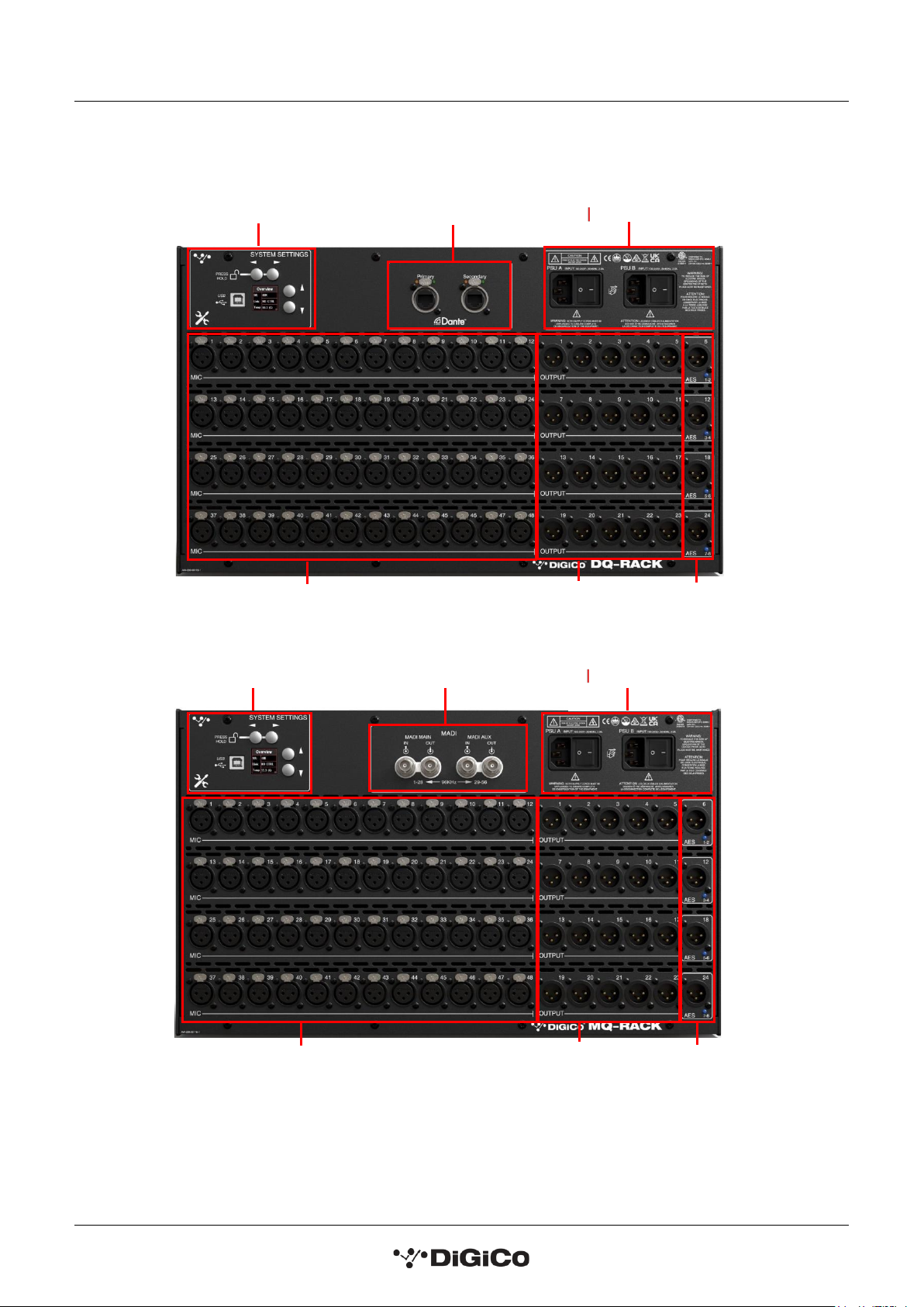
The Q-Rack Unit is a 19-inch chassis with a control panel and PSUs at the top. It is a standard 19" rack mount
wide - Dimensions: 482.7mm (w) x 253mm (d) x 265.9mm (h). Weight: 11kg
Rack Mains Earthing
The Q-Rack Unit must be earthed to the mains earth according to the safety instructions included with the
rack. The rack has twin supplies each with their own separate mains power connections, with 2 IEC mains
inputs per rack, which must be separately connected to the mains earth.
Rack Control Panel Connections
MADI I/O BNC 4 sockets (2 Pairs) of I/O to Console
USB type B
Mains Power IEC power x 2 Dual redundant supplies
Power Requirements: 100-240V~, 50-60Hz, 2.0A
Requires 2 separate mains connections.
Input / Output Slots
Below the panel, the Rack Unit has Input and Output slots consisting of 48 Analogue Mic/Line Inputs and 24
Analogue outputs (4 of these are switchable to AES Mode).
DQ & MQ-Rack User Guide 1.1 Introduction
7
NOTE: DQ & MQ-Racks are only compatible with SD and Quantum consoles running
V1454+ of application software
System Settings
Controls
D ual Redundant PSUs
48 MIC inputs
20 Analogue
Outs
4 Line Out/AES
Switchable Outs
DANTE Ports
D ual Redundant PSUs
MADI Pod
System Settings
Controls
20 Analogue
Outs
4 Line Out/AES
Switchable Outs
48 MIC inputs
DQ & MQ-Rack User Guide 1.2 Q-Rack Power
8
1.2 Q-Rack Power
The Q-Rack has dual redundant power supplies. The rack should be operated with both power supplies on
whenever possible.
1.3 Q-Rack Clocking
The Q-Rack will receive clock sync from the connected console in normal operation. It can run at 48KHz or
96KHz when clocked by the console.
The MQ-Rack can also receive sync from its own internal clock- see section 1.5.13 Internal SR Menu.
1.4 Q-Rack Sockets
The Q-Racks have a set of 48 mic inputs and 24 line outputs, 4 of which can be changed to AES or line out via
the system settings on the rack.
Note: On Quantum consoles, the status of the 4 switchable Line Out/AES sockets can be viewed and
changed between AES and Line outputs in the Audio I/O panel.
Analogue Line/AES Output sockets ......................................
The 4 switchable output sockets (6, 12, 18 and 24) have a LED indicator light below the socket.
A blue light on one of the switchable AES/Line output sockets indicates that the socket is set to be an AES
output in its current state.

DQ & MQ-Rack User Guide 1.5 Using the Q-Rack Menu System
9
1.5 Using the Q-Rack Menu System
The LCD Menu System on the rack is normally in a locked state and cannot be accessed.
The main display will be visible and if the rack is not connected to a console the background colour will be light
blue with a band of red on the MQ-Rack and flashing red on the DQ-Rack.
If the rack is connected to a console the display will flash green.
MQ-Rack Lock screen
DQ-Rack Lock screen
Pressing and holding the 2 buttons marked with left and right arrows for 2 seconds unlocks the Menu System.
The Left/Right buttons scroll through the pages in the Menu System and the Up/Down buttons are used to
select each item within pages that have multiple items. When an item's value can be changed the Left/Right
arrows are used for this.
If the rack is left in an idle state for 2 minutes, it will relock itself.
Please refer to the following diagram for menu navigation details.
DQ & MQ-Rack User Guide 1.5 Using the Q-Rack Menu System
10
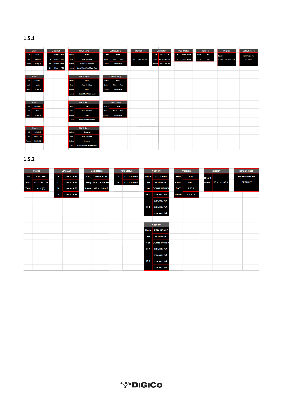
MQ-Rack navigation
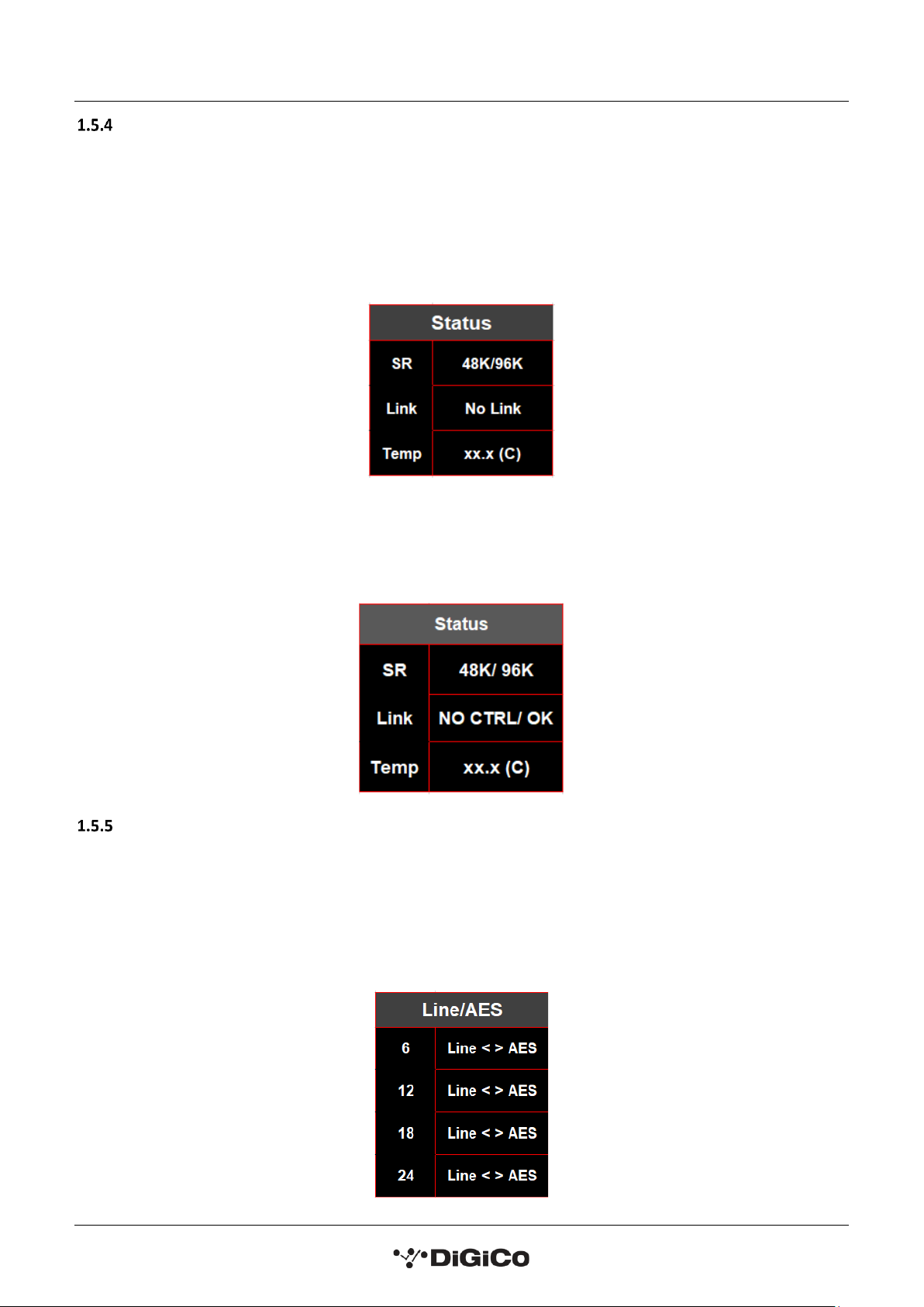
DQ-Rack navigation
Note: The Q-Rack navigation maps display DQ-Rack and MQ-Rack menu pages in order from left to right.
Wherever a “/” (or alternatively a menu page has been created underneath another menu page) has
been used, the messages listed can be displayed depending on the rack’s connections. These cannot be
changed by the user in the rack menu. Where a “<” or “>” has been used this means the displayed
parameter values can be changed by the user in rack system settings using the left and right arrows, the
use of “<…>” means there is a selection of values to choose from in between the displayed parameter
values.

DQ & MQ-Rack User Guide 1.5 Using the Q-Rack Menu System
11
Main Display.......................................................................
The main display is always visible when the Menu System is in a locked state.
On the MQ-Rack it indicates:
Link: whether the rack and the console are linked.
96k/48k: the current sample rate of the rack.
S: the clock source to which the rack is syncing.
Outs: which MADI input has control/access to the output sockets.
Lock: this reports whether the incoming MADI clock is stable (LOCK) or not (NO LOCK).
MQ-Rack Main Display
On the DQ-Rack it indicates:
SR: sample rate at which the rack is running at.
Mode: whether the rack is in switched or redundant connection mode.
Link: this shows if the rack is receiving control information from the connected device. When receiving control
data, the rack will display OK and when not receiving control data it will display NO CTRL.
Note: On a DQ-Rack, the DANTE device name (which can be set in DANTE Controller) is displayed at the
top of the system setting LCD screen when in a locked state.
DQ-Rack Main Display
DQ & MQ-Rack User Guide 1.5 Using the Q-Rack Menu System
12
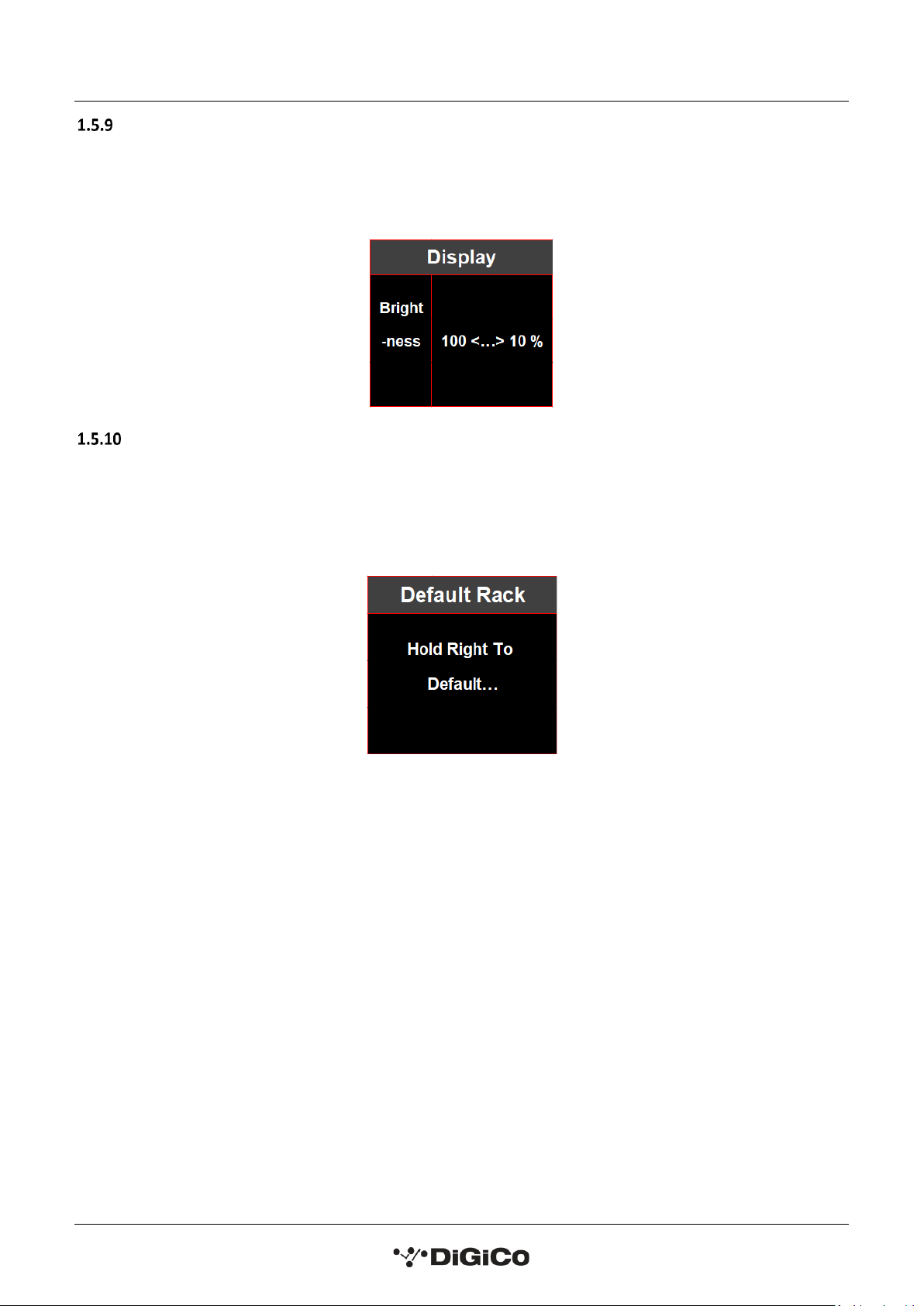
Status Menu.......................................................
The Status menu is the first menu visible once the rack is unlocked. No adjustments are possible from this
menu.
On the MQ-Rack the status menu page displays the sample rate the rack is working at, whether it has a link via
the MADI MAIN, MADI AUX or both and the current temperature of the rack.
MQ-Rack Status Menu
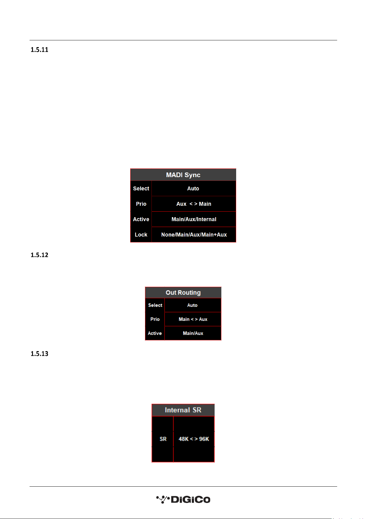
On the DQ-Rack the status menu shows the working sample rate, whether the rack is receiving control
information and the current internal temperature of the rack.
DQ- Rack Status Menu
Line/AES Menu ...................................................
In the Line/AES menu page, the user can change the state of the 4 switchable Line/AES outputs, by selecting
the desired socket and changing it between Line and AES using the left and right buttons. When the socket is
in AES mode the LED light below the socket will light up blue.
Note: On Quantum consoles, this setting’s status can be displayed and switched from within the Audio
I/O panel on the console.

DQ & MQ-Rack User Guide 1.5 Using the Q-Rack Menu System
13
Oscillators Menu........................................................................
In the Oscillators menu, the user can apply the rack’s internal oscillator signal all output sockets. To enable the
oscillator, select the out option, hold the right button down and a bar next to the word OFF will begin to fill,
when the bar fills, the word will change to ON and signal will be applied to all 24 outputs.
From within the Oscillators menu one of 8 frequencies can be selected between 20Hz and 20KHz, on default
settings the frequency is set to 1KHz.
The level of the oscillator can also be changed to be a range of volumes between a value of -96dB and 0dB, at
default setting the level is -96dB.
PSU Status Menu .........................................................................
The PSU Status menu page shows readings for all rack PSU voltages. No adjustments are possible from this
menu.
Version Menu .................................................
The Version menu page shows the software versions of the Host and FPGA currently installed in the rack.
No adjustments are possible from this menu.
MQ-Rack version menu
On the DQ-Rack there are additional versions displayed, for the DNT and Dante software versions.
DQ-Rack version menu
DQ & MQ-Rack User Guide 1.5 Using the Q-Rack Menu System
14
Display Menu ................................................................
The brightness of the LCD system settings screen can be adjusted from within the rack in the display menu.
The default value is set to 100% brightness and can be adjusted using the left and right buttons in increments
of 10%, down to a minimum of 10% brightness.
Default Rack Menu ................................................................
This page allows the user to set all rack parameters to their default values.
When the display shows Hold Right To Default… as highlighted, hold the Right arrow button to confirm and a
bar will begin to fill underneath the text, when the bar fills the rack will reset and the system setting will lock
again.
DQ & MQ-Rack User Guide 1.5 Using the Q-Rack Menu System
15
MADI Sync Menu (MQ-Rack only) ................................................................
This page allows selection of the MQ-Rack sync source.
When selecting a sync source:
Auto will automatically sync to any connection with a clock signal. If the rack is not receiving a connection with
a valid clock signal it will use its internal sync. MADI MAIN and MADI AUX sockets can be given priority so that
if a clock signal comes into the rack it will sync to the port with priority.
Selecting the Main or Aux setting in the Select parameter forces the active sync source to be the selected
connection and is not affected by the priority option.
The Active parameter shows which socket the rack is currently syncing to.
The Lock parameter displays from which sources a stable clocking source is received.
Out Routing Menu (MQ-Rack only) ..............................................................
The Out Routing menu is for selecting which MADI inputs from a console can output via the MQ-Rack’s 24
physical outputs.
Internal SR Menu (MQ-Rack only) ...........................................................
The Internal SR menu allows selection of the rack’s sample rate.
This is only possible to sync from the internal clock if the MADI Sync Active is internal.
Available options are 48K and 96K
DQ & MQ-Rack User Guide 1.5 Using the Q-Rack Menu System
16
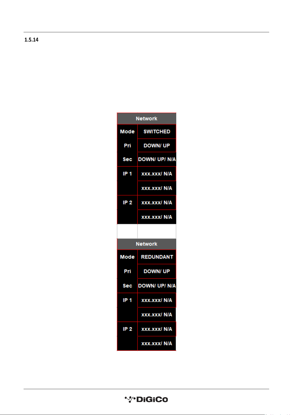
Network Menu (DQ-Rack only) ...........................................................
The DQ-Rack has two ethernet ports (Primary and Secondary) which can be used to connect the rack to a
DANTE network. The rack can either operate in SWITCHED or REDUNDANT mode which can be set in DANTE
Controller. Primary and secondary port status are reported in the DQ-Rack Network menu as either UP
meaning the port is connected with a valid IP address or DOWN meaning the port is not connected with a valid
IP address. The IP address for each ethernet port is reported below primary and secondary port status.
Note: When first powering on a DQ-Rack, whilst the rack is initialising a “Reset” message will be
displayed in network mode field.

DQ & MQ-Rack User Guide 1.6 Connecting a DANTE rack
17
1.6 Connecting a DANTE rack
PLEASE NOTE that for the connection and use of the A168D & A164D Dante IO boxes and DQ Rack, there
is a requirement for the following firmware updates to the Dante 64@96 DMI card:
1. DMI Dante 64@96 firmware update (v103) which is currently available (June 2021) as part of the
Quantum 2 V1454 update package and all other DMI equipped SD/Quantum consoles running software
application version v1280+.
2. A Dante firmware update (4.0.20) for the DMI Dante 64@96 card is required for control of the DQ-
Rack, details on how to update the DMI firmware can be found in TN514 available on the website and is
included in the Quantum 2 V1454 update package.
3. If A168D and A164D Dante IO Racks are used with SD/Quantum applications earlier than V1454 they
should remain using Dante DMI firmware version 4.0.19 which can be updated using Dante Updater in
Dante Controller.
Users who wish to use A164D and A168D with SD/Quantum applications V1454 or higher, need to
upgrade the Digico firmware in these IO devices to V1.5. This is done using the new DiGiCo Dante Rack
Utility and can be done over an IP Network. The update process is detailed in TN515.
Socket parameters on A168D, A164D and DQ-racks can be controlled in the same way as other DiGiCo I/O
racks when connected to a Dante 64@96 DMI card and routed in Audinate’s “Dante Controller” software.
With a DMI Dante 64@96 card installed in a console, access to 64 channels of IO to/from the Dante network is
provided.
A Dante IO box can provide a specific number of IO on the Dante network according to the rack’s capability.
168D = 16 analogue In and 8 analogue Out.
DQ-Rack = 48 analogue In and 24 analogue Out of which 4 are switchable AES Outs.
Any Dante network may have many more devices on it than just a single console and rack.
There might be multiple Dante equipped consoles, multiple racks and other Dante devices.
When a console has a DMI Dante fitted, it “sees” that DMI as a 64 channel interface device to/from the Dante
network.
The source device of the audio signals it is receiving across that interface and the destination device of any
signals that it is sending out across that interface are generally “unknown” to the console.
The critical component in determining where the audio is going to/from is the Dante network controller which
is responsible for setting up audio paths (routing) on the network.
As an example, using just a single console and a single rack, the console could use its DMI Dante channel 1 as
an input signal to its own console Input Channel 1 but the audio signal which appeared on that DMI Dante
channel could be any signal from the Dante IO rack and is determined by the routing in the Dante Controller.
With the following routing in place, a console that selects any of the DMI card channels 1-16 as an input source
will receive the signal from the same numbered Rack Input socket –this is a logical setup.

DQ & MQ-Rack User Guide 1.6 Connecting a DANTE rack
18
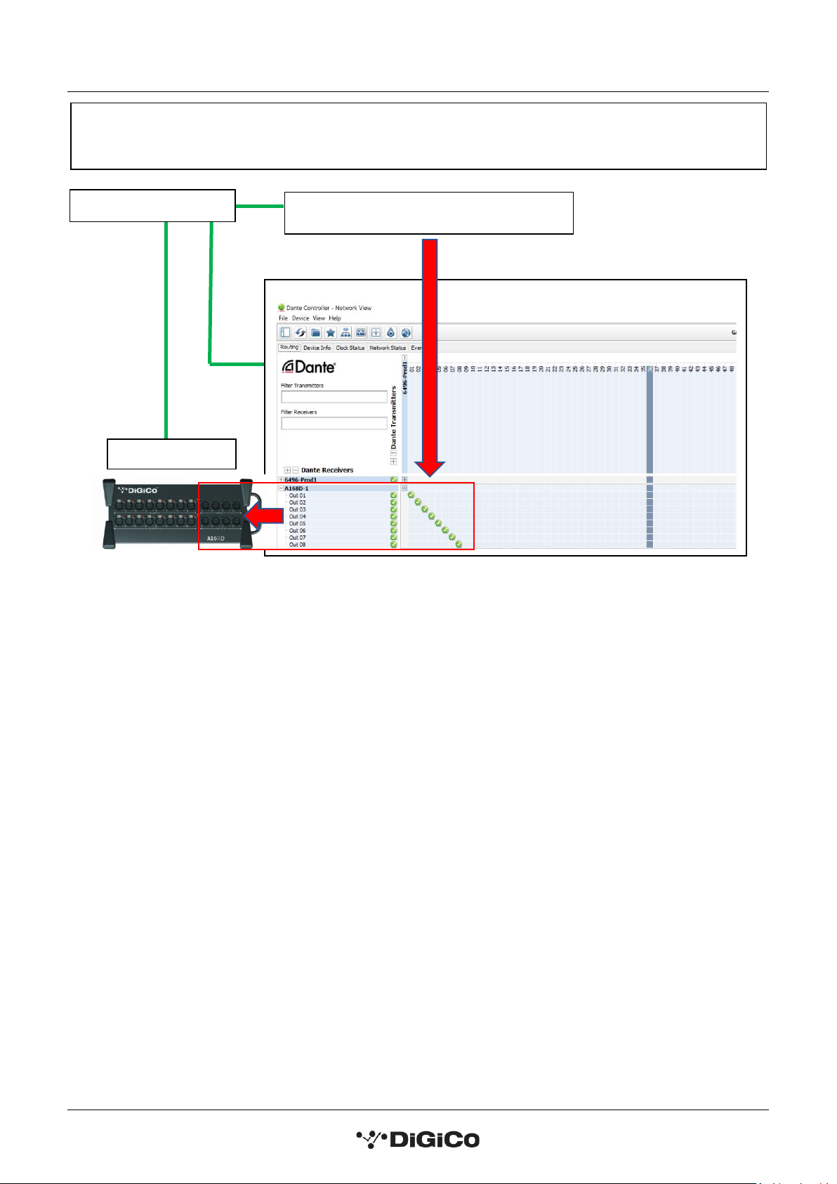
In this example, a console that routes signal to DMI card output channels 1-8 will be sending them to the same
numbered Rack Output socket.
Dante Controller & Routing
Dante Rack
Inputs
Network Switch
Console 1
DMI 64@96 is a Receiver in this case.
Each channel receives the same numbered input
socket from the rack.
DANTE Rack is a Transmitter in this case.
Each of the 16 Rack input sockets are routed to the same numbered
DMI 64@96 channel
DQ & MQ-Rack User Guide 1.6 Connecting a DANTE rack
19
Dante Controller & Routing
Console 1 –DMI Outputs
Dante Rack
Outputs
Network Switch
Console 1 DMI is a Transmitter in this case.
Each of the DMI 64@96 outputs 1-8 are routed to same numbered Rack output sockets
This manual suits for next models
1
Table of contents
Other digico Mixer manuals


